Note: Descriptions are shown in the official language in which they were submitted.
CA 02901778 2015-08-19
4351-11-28.997
Pane with Thermal Radiation Reflecting Coating
The invention relates to a pane with thermal radiation reflecting coating, a
method for
its production, and the use of a darkening layer in a pane with such a
coating.
The interior of a motor vehicle can heat up greatly in the summer with high
ambient
temperatures and intense direct sunlight. When the outside temperature is
lower than
the temperature in the vehicle interior, which occurs in particular in the
winter, a cold
pane acts as a heat sink, which is perceived as unpleasant by the occupants.
High
heating performance of the climate control system must also be provided to
prevent
excessive cooling of the interior through the motor vehicle windows.
Thermal radiation reflecting coatings (so-called "low-E coatings") are known.
Such a
coating reflects a significant part of sunlight, in particular in the infrared
range, which, in
the summer, results in reduced warming of the vehicle interior. Moreover, the
coating
reduces the emission of long-wave thermal radiation of a heated pane into the
vehicle
interior when the coating is applied on the surface of a pane facing the
vehicle interior.
Moreover, in the case of low outside temperatures in the winter, such a
coating
reduces the outward emission of heat from the interior into the external
surroundings.
For aesthetic or thermal reasons, it can be desirable for a motor vehicle
window pane
to have reduced light transmittance. This is frequently the case, for example,
with rear
side windows, rear windows, or roof panels. Such a pane can be produced
through the
use of a transmittance-reducing thermal radiation reflecting coating.
Transmittance-
reducing thermal radiation reflecting coatings that contain functional layers
made of
niobium, tantalum, nickel, chromium, zirconium, or alloys thereof are known to
the
person skilled in the art, for example, from US7592068B2, US7923131B2, and
W02004076174A1. Due to the low light transmittance of the coating, layer
defects, in
particular production-related defects which can be present, have an
undesirably high
contrast. Even very small defects with a size of, for example, ca. 100 m can
be
disturbingly noticeable to an observer, in particular when looking through the
pane.
Such layer defects can, for example, occur in that before and/or during a
coating
process, particles contaminate the surface of the pane to be coated and are
released
from the surface after coating. Particles can also be released from the
surface during
subsequent thermal treatment of the surface of the pane.
CA 02901778 2015-08-19
2
4351-11-28.997
To avoid the disadvantages of transmittance-reducing coatings, it is possible
to apply
transparente thermal radiation reflecting coatings on tinted panes. Such
coatings can
contain functional layers based on a transparent conductive oxide, such as
indium tin
oxide, and are known, for example, from EP 2 141 135 Al, WO 2010115558 Al, and
WO 2011105991 Al. Panes with very low light transmittance of, for example,
less than
8% are, however, not easily realizable in this manner, since, customarily,
glasses with
light transmittance of less than 10% are not commercially available.
Frequently, after the application of the coating, panes are to be subjected to
a thermal
treatment and a mechanical transformation. Panes for the automotive sector,
for
example, side windows and rear windows in the form of single pane safety glass
and
roof panels, side windows, and rear windows in the form of composite safety
glass are
typically bent and frequently provided with prestressing or partial
prestressing in this
process. The bending and prestressing of the pane also places particular
demands on
the coating.
From US 2008/0070045 Al, another pane with a low-E coating is known, wherein
the
functional layer contains a transparent conductive oxide. The coating contains
a layer
for the absorption of thermal radiation, for example, made of titanium
nitride. The
thickness of the absorption layer is not specified.
From US 2005/0123772 Al, a low-E coating with a functional layer made of
silver is
known. The coating contains a light-absorbing layer made of titanium nitride.
Low-E
coatings based on silver are very susceptible to corrosion and can,
consequently, not
be used on pane surfaces with contact with the environment. Their use is
typically
restricted to the composite pane surfaces turned toward the intermediate
layer. Use on
the interior-side surface of a pane is, consequently, not possible.
The object of the present invention consists in providing an improved pane
with thermal
radiation reflecting coating, wherein the thermal radiation reflecting coating
reduces the
transmittance of the pane in the visible spectral range. The coating should
also be
corrosion resistant and should not be damaged during the bending and
prestressing of
the pane. Moreover, a method for producing the pane should be provided.
CA 02901778 2016-10-24
3
4351-11-28.997
The object of the present invention is accomplished according to the invention
by a
pane with thermal radiation reflecting coating.
The pane according to the invention with thermal radiation reflecting coating
comprises
a substrate and at least one thermal radiation reflecting coating on at least
one of the
surfaces of the substrate, wherein the coating, proceeding from the substrate,
comprises at least
- one lower dielectric layer,
- one functional layer that contains at least one transparent, electrically
conductive
oxide, and
- one upper dielectric layer,
and wherein at least one darkening layer is arranged below the lower
dielectric layer,
between the lower dielectric layer and the functional layer, between the
functional layer
and the upper dielectric layer, and/or above the upper dielectric layer,
and wherein the darkening layer contains at least one metal, one metal
nitride, and/or
one metal carbide with a melting point greater than 1900 C and a specific
electrical
resistivity less than 500 pohm*cm.
The thermal radiation reflecting coating according to the invention is a layer
stack,
which comprises at least the following individual layers in the order
indicated,
proceeding from the substrate:
- one lower dielectric layer,
- above the lower dielectric layer, one functional layer that contains at
least one
transparent, electrically conductive oxide (TCO), and
- above the functional layer, one upper dielectric layer.
The coating moreover comprises at least one darkening layer according to the
invention.
When a first layer is arranged above a second layer, this means, in the
context of the
invention, that the first layer is arranged farther from the substrate than
the second
layer. When a first layer is arranged below a second layer, this means, in the
context of
the invention, that the second layer is arranged farther from the substrate
than the first
layer.
CA 02901778 2015-08-19
4
4351-11-28.997
When a first layer is arranged above or below a second layer, this does not
necessarily
mean, in the context of the invention, that the first and the second layer are
situated in
direct contact with each other. One or a plurality of additional layers can be
arranged
between the first and the second layer, unless this is explicitly ruled out.
The uppermost layer of the coating is, in the context of the invention, that
layer that is
the greatest distance from the substrate. The lowest layer of the coating is,
in the
context of the invention, that layer that is the least distance from the
substrate.
The values indicated for the specific electrical resistivity are measured at a
temperature
of 20 C. The values indicated for refractive indices are measured at a
wavelength of
550 nm.
The person skilled in the art can, for example, find the values indicated for
the melting
point and the specific electrical resistivity in tables or data sheets.
Typically, the values
indicated there are for a solid. In the case of thin films, the melting point
and the
specific electrical resistivity can deviate therefrom. The tabulated values
for the solids
nevertheless give the person skilled in the art an adequate criterion for the
selection of
suitable materials for the darkening layer according to the invention. The
values
indicated for the melting point and the specific electrical resistivity must
be understood
in this context.
When a layer or another element contains at least one material, this includes,
in the
context of the invention, the case in which the layer is made of the material.
The metal, metal nitride, and/or metal carbide according to the invention of
the
darkening layer has a low specific electrical resistivity and, thus, a
definite electrical
conductivity. By means of such a conductive darkening layer, the transmittance
in the
visible spectral range of the thermal radiation reflecting coating is reduced,
in particular
by absorption and/or reflection. Of course, the darkening layer can also
reduce the
transmittance in other spectral ranges, for example, the infrared range. The
transmittance level can be adjusted by the number and thickness, as well as
the
material of the darkening layers. Thus, even very dark panes can be realized,
in
particular, if the coating according to the invention is used on tinted panes.
This is a
major advantage of the invention.
CA 02901778 2015-08-19
4351-11-28.997
The metal, metal nitride, and/or metal carbide according to the invention of
the
darkening layer also has a high melting point. Such darkening layers are
advantageously corrosion and oxidation resistant. Consequently, the coated
pane can
even be subjected to a temperature treatment, a bending process, and/or a
prestressing process without the coating being damaged (for instance, by
cracks in the
darkening layer) or for the light transmittance being increased again as a
result of
oxidation of the darkening layer. This is another major advantage of the
present
invention.
The pane according to the invention is preferably provided, in an opening, for
example,
of a motor vehicle or a building, to separate the interior from the external
environment.
The coating according to the invention is preferably arranged on the surface
of the
substrate that is intended to be turned toward the the interior in the
installed position of
the pane. This is particularly advantageous with regard to the thermal comfort
in the
interior. The surface that is intended to be turned toward the interior in the
installed
position of the pane is referred to, in the context of the invention, as the
interior-side
surface. The coating according to the invention can, in the case of high
external
temperatures and sunlight, particularly effectively at least partially reflect
the thermal
radiation radiated by the entire pane in the direction of the interior. In the
case of low
outside temperatures, the coating according to the invention can effectively
reflect the
thermal radiation radiated out of the interior and thus reduce the action of
the cold pane
as a heat sink.
The interior-side emissivity of the pane according to the invention is
preferably less
than or equal to 35%, particularly preferably less than or equal to 25%, most
particularly preferably less than or equal to 20%. Here, the term "interior-
side
emissivity" refers to the measurement that indicates how much thermal
radiation the
pane gives off into an interior space, for example, of a building or a motor
vehicle, in
the installed position compared to an ideal thermal emitter (a black body). In
the
context of the invention, "emissivity" means the normal emission level at 283
K
according to the standard EN 12898.
The pane according to the invention has, in an advantageous embodiment,
transmittance in the visible spectral range of less than 25%, preferably less
than 15%,
particularly preferably less than 10%, most particularly preferably less than
8%, and in
particular less than 6%. The invention is particularly advantageous for panes
with
CA 02901778 2015-08-19
6
4351-11-28.997
transmittance of less than 10%. Such panes are difficult to realize by means
of a tinted
substrate alone because such heavily tinted substrates are typically not
available
commercially. Panes with such low transmittance can be desirable, in
particular as a
side window, rear window, or roof panel of a motor vehicle or also in
buildings.
The value of the pane according to the invention for the total energy input
from sunlight
is preferably less than 50%, particularly preferably less than 40%, most
particularly
preferably less than 30%. This value is also known to the person skilled in
the art as
the TTS value ("total transmitted sun").
The sheet resistance of the coating according to the invention is preferably
from 10
ohm/square to 50 ohm/square, particularly preferably from 15 ohm/square to 30
ohm/square.
The thermal radiation reflecting coating includes, according to the invention,
at least
one darkening layer. The coating can also include multiple darkening layers,
for
example, two, three, or four darkening layers, which can be desirable for
optical or
mechanical reasons.
In an advantageous embodiment, the coating contains one or two darkening
layers
according to the invention. This is particularly advantageous with regard to
simple
production of the coating.
The darkening layer or the multiple darkening layers can be arranged, for
example,
below the lower dielectric layer, between the lower dielectric layer and the
functional
layer, between the functional layer and the upper dielectric layer, and/or
above the
upper dielectric layer.
In particularly advantageous embodiments, the darkening layer is or the
darkening
layers are arranged between the lower dielectric layer and the functional
layer and/or
between the functional layer and the upper dielectric layer. Preferably, in
this case, the
darkening layers are in direct contact with the functional layer. It has been
surprisingly
demonstrated that such a thermal radiation reflecting coating is particularly
well-suited
to withstand a temperature treatment, a bending process, and a prestressing
process
undamaged.
CA 02901778 2015-08-19
7
4351-11-28.997
The darkening layer preferably has a thickness from 2 nm to 50 nm,
particularly
preferably from 5 nm to 40 nm, most particularly preferably from 10 nm to 30
nm. This
is particularly advantageous with regard to the transmittance-reducing action
as well as
the corrosion resistance and bendability of the darkening layer.
The darkening layer contains, according to the invention, at least one metal,
one metal
nitride, and/or one metal carbide. Here, in the context of the invention, the
term
"metals" also includes alloys of two or more metals. Likewise included are
mixed
nitrides and mixed carbides of two or more metals as well as alloys, mixed
nitrides, or
mixed carbides of a metal with silicon and/or aluminum.
Metals and metal carbides can contain small production-related amounts of
oxygen.
The oxygen content is, in this case, preferably less than 30 wt.-%,
particularly
preferably less than 20 wt.-%.
The metal that is contained in the darkening layer or whose oxide or nitride
is contained
in the darkening layer is preferably selected from the transition metals,
particularly
preferably from the groups IV B, V B, and VI B of the periodic system. The
darkening
layer contains preferably at least one metal, metal nitride, or metal carbide
from the
group consisting of hafnium, niobiumium, tantalum, molybdenum, tungsten,
titanium
nitride, zirconium nitride, hafnium nitride, vanadium nitride, niobium
nitride, tantalum
nitride, titanium carbide, zirconium carbide, hafnium carbide, vanadium
carbide,
niobium carbide, tantalum carbide, molybdenum carbide, and tungsten carbide,
or
mixtures or alloys thereof. The melting points Ts and the specific electrical
resistivities
p of the materials indicated are summarized in Table 1 (cf. also H.O. Pierson:
Handbook of Refractory Carbides and Nitrides. Westwood: Noyes Publications,
1996).
The melting point of the metal, of the metal nitride, and/or of the metal
carbide is
preferably greater than 2200 C, particularly preferably greater than 2500 C.
This is
particularly advantageous with regard to the corrosion and oxidation
resistance of the
darkening layer.
The specific electrical resistivity of the metal, of the metal nitride, and/or
of the metal
carbide is preferably less than 200 pohm*cm. This is particularly advantageous
with
regard to the transmittance-reducing action of the darkening layer.
CA 02901778 2015-08-19
8
4351-11-28.997
The darkening layer contains preferably at least one metal, metal nitride, or
metal
carbide from the group consisting of hafnium, niobiumium, tantalum,
molybdenum,
tungsten, titanium nitride, zirconium nitride, hafnium nitride, niobium
nitride, tantalum
nitride, titanium carbide, zirconium carbide, hafnium carbide, vanadium
carbide,
niobium carbide, tantalum carbide, molybdenum carbide, and tungsten carbide,
or
mixtures or alloys thereof, or alloys, mixed nitrides or mixed carbides
thereof with
silicon or aluminum. This is, due to the high melting point greater than 2200
C,
particularly advantageous for the corrosion resistance of the darkening layer.
The darkening layer contains most particularly preferably at least one metal,
metal
nitride, or metal carbide from the group consisting of tantalum, molybdenum,
tungsten,
titanium nitride, zirconium nitride, hafnium nitride, tantalum nitride,
titanium carbide,
zirconium carbide, hafnium carbide, vanadium carbide, niobium carbide,
tantalum
carbide, molybdenum carbide, and tungsten carbide, or mixtures or alloys
thereof, or
alloys, mixed nitrides or mixed carbides thereof with silicon or aluminum.
This is, due to
the high melting point greater than 2500 C, most particularly advantageous
for the
corrosion resistance of the darkening layer.
In principle, nitrides and carbides are preferred to metals or alloys for the
darkening
layer. It has been demonstrated that such darkening layers are particularly
corrosion
and oxidation resistant and damage resistant.
The metal nitride and the metal carbide can be stoichiometric,
substoichiometric, or
supersubstoichiometric relative to the nitrogen or relative to the carbon.
CA 02901778 2015-08-19
9
4351-11-28.997
Table 1
T p Ts p Ts
Group
1 C / umm / C / Om 1 C /42cm
TiN 2950 20 TiC 3067 68
IV B ZrN 2980 14 ZrC 3420 43
Hf 2230 35 HfN 3387 33 HfC 3928 37
VN 2177 85 VC 2830 60
V B Nb 2468 13 NbN 2400 68 NbC 3600 35
Ta 2996 12 TaN 3093 193 TaC 3950 25
VI B Mo 2620 5.6 Mo2C 2520 71
W 3410 5.3 WC 3410 22
The functional layer has reflecting properties for thermal radiation, in
particular infrared
radiation, yet is largely transparent in the visible spectral range. According
to the
invention, the functional layer contains at least one transparent,
electrically conductive
oxide (TCO). The refractive index of the material of the functional layer is
preferably
from 1.7 to 2.3. The functional layer preferably contains at least indium tin
oxide (ITO).
Thus, particularly good results are obtained with regard to the emissivity and
the
bendability of the coating according to the invention.
A functional layer based on TCO, in particular ITO, is not susceptible to
corrosion and
is, consequently, particularly suited for use on the interior-side surface of
the pane.
The indium tin oxide is preferably deposited using magnetically enhanced
cathodic
sputtering with a target made of indium tin oxide. The target preferably
contains from
75 wt.-% to 95 wt.-% indium oxide and from 5 wt.-% to 25 wt.-% tin oxide as
well as
production-related admixtures. The deposition of the indium tin oxide is
preferably done
under a protective gas atmosphere, for example, argon. A small amount of
oxygen can
also be added to the protective gas, for example, to improve the homogeneity
of the
functional layer.
Alternatively, the target can preferably contain at least from 75 wt.-% to 95
wt.-%
indium and from 5 wt.-% to 25 wt.-% tin. The deposition of the indium tin
oxide is then
CA 02901778 2015-08-19
4351-11-28.997
done preferably under the addition of oxygen as reaction gas during the
cathodic
sputtering.
The emissivity of the pane according to the invention can be influenced by the
thickness of the functional layer. The thickness of the functional layer is
preferably from
40 nm to 200 nm, particularly preferably from 90 nm to 150 nm, and most
particularly
preferably from 100 nm to 140 nm, for example, roughly 120 nm. In this range
for the
thickness of the functional layer, particularly advantageous values for
emissivity and a
particularly advantageous capability of the functional layer to withstand
mechanical
transformation such as bending or prestressing without damage are obtained.
However, the functional layer can also include other transparent, electrically
conductive
oxides, for example, fluorine-doped tin oxide (Sn02:F), antimony-doped tin
oxide
(Sn02:Sb), mixed indium/zinc oxide (IZO), gallium-doped or aluminum-doped zinc
oxide, niobium-doped titanium oxide, cadmium stannate, and / or zinc stannate.
The thermal radiation reflecting coating is a layer stack, which, according to
the
invention, includes at least two dielectric layers, namely a lower dielectric
layer and an
upper dielectric layer. The lower dielectric layer is arranged below the
functional layer;
the upper dielectric layer is arranged above the functional layer. The coating
according
to the invention can however also include one or a plurality of additional
dielectric
layers, which can be arranged below and/or above the functional layer.
The dielectric layers can contain, for example, silicon oxide (SiO2), silicon
nitride
(Si3N4), zinc oxide (Zn0), tin oxide (Sn02), mixed tin zinc oxide (SnZn0x),
zirconium
oxide (ZrO2), hafnium oxide (Hf02), tantalum oxide (Ta205), tungsten oxide
(W03),
niobium oxide(Nb205), or titanium oxide(TiO2) and have, for example,
thicknesses from
5 nm to 200 nm.
The darkening layer or the darkening layers can, in principle, be arranged at
any
position in the layer stack. The darkening layer can be arranged, for example,
between
the functional layer and the adjacent dielectric layer above and/or below the
functional
layer. The darkening layer can be arranged, for example, below the lowest
dielectric
layer. The darkening layer can be arranged, for example, above the uppermost
dielectric layer. The darkening layer can also be arranged between two
adjacent
dielectric layers.
CA 02901778 2015-08-19
11
4351-11-28.997
In a preferred embodiment of the invention, the lower dielectric layer is an
adhesive
layer. The adhesive layer results in a durably stable adhesion of the layers
deposited
above the adhesive layer on the substrate. The adhesive layer further prevents
the
accumulation of ions diffusing out of the substrate in the boundary area to
the
functional layer, in particular of sodium ions, if the substrate is made of
glass. Such
ions can lead to corrosion and to low adhesion of the functional layer. The
adhesive
layer is, consequently, particularly advantageous with regard to the stability
of the
functional layer.
The adhesive layer preferably contains at least one oxide or one nitride. The
adhesive
layer particularly preferably contains silicon oxide (SiO2) or silicon nitride
(Si3N4). This is
particularly advantageous with regard to the adhesion of the layers deposited
above
the adhesive layer on the substrate. The silicon oxide can have dopants, for
example,
fluorine, carbon, nitrogen, boron, phosphorus, and / or aluminum. The silicon
oxide or
silicon nitride is most particularly preferably doped with aluminum (Si02:Al,
Si3N4:A1),
doped with boron (Si02:B, Si3N4:B), or doped with zirconium (Si02:Zr,
Si3N4:Zr). This is
particularly advantageous with regard to the optical properties of the coating
as well as
the speed of the application of the adhesive layer, for example, by cathodic
sputtering.
The silicon oxide or the silicon nitride is preferably deposited using
magnetically
enhanced cathodic sputtering with a target that contains at least silicon. The
target for
the deposition of an adhesive layer containing aluminum-doped silicon oxide or
silicon
nitride preferably contains from 80 wt.-% to 95 wt.-% silicon and from 5 wt.-%
to 20 wt.-
% aluminum as well as production-related admixtures. The target for the
deposition of
an adhesive layer containing boron-doped silicon oxide or silicon nitride
preferably
contains from 99.9990 wt.-% to 99.9999 wt.-% silicon and from 0.0001 wt.-% to
0.001
wt.-% boron as well as production-related admixtures. The target for the
deposition of
an adhesive layer containing zirconium-doped silicon oxide or silicon nitride
preferably
contains from 60 wt.-% to 90 wt.-% silicon and from 10 wt.-% to 40 wt.-%
zirconium as
well as production-related admixtures. The deposition is preferably done under
addition
of oxygen as reaction gas in the case of the silicon oxide; under the addition
of nitrogen
as reaction gas in the case of the silicon nitride during the cathodic
sputtering.
The doping of the adhesive layer can also improve the smoothness of the layers
applied above the adhesive layer. High smoothness of layers is particularly
CA 02901778 2015-08-19
12
4351-11-28.997
advantageous in the case of use of the pane according to the invention in the
motor
vehicle sector since, by this means, an unpleasant rough surface feel of the
pane is
avoided. When the pane according to the invention is a side window pane, it
can be
moved with low friction to the sealing lips.
However, the adhesive layer can also contain other materials, for example,
other
oxides such as TiO2, A1203, Ta205, Y203, ZrO2, Hf02, W03, Nb2O5 ZnO, Sn02, and
/ or
ZnSnOx or nitrides such as AIN.
The adhesive layer preferably has a thickness from 10 nm to 150 nm,
particularly
preferably from 15 nm to 50 nm, for example, roughly 30 nm. This is
particularly
advantageous with regard to the adhesion of the coating according to the
invention and
the prevention of the diffusion of ions from the substrate into the functional
layer.
In a preferred embodiment of the invention, the upper dielectric layer is a
barrier layer
for regulating oxygen diffusion during a temperature treatment of the pane.
Thus, by
means of the barrier layer, the oxygen content of the functional layer can be
influenced
and adjusted, which has a definite influence on the properties of the
functional layer.
Both an excessively low oxygen content and an excessively high oxygen content
result
in excessively high sheet resistance and, thus, in excessively high
emissivity. In
addition, an excessively low oxygen content results in a definite, often
undesirable
color impression. An excessively high oxygen content of the functional layer
results in
the fact that the functional layer is damaged during the bending, which is
evidenced in
particular as cracks within the functional layer.
The thickness of the barrier layer is preferably from 5 nm to 50 nm,
particularly
preferably from 7 nm to 40 nm, most particularly preferably from 10 nm to 30
nm. Thus,
particularly good results with regard to sheet resistance and bendability are
obtained.
In addition, a barrier layer with these thicknesses advantageously protects
the coating
against corrosion from a moist atmosphere.
The refractive index of the material of the barrier layer is preferably
greater than or
equal to the refractive index of the material of the functional layer. The
refractive index
of the material of the barrier layer is particularly preferably from 1.7 to
2.3. Thus,
advantageous optical properties of the coating are obtained, in particular an
aesthetic
color impression during the reflection of light.
CA 02901778 2015-08-19
13
4351-11-28.997
The barrier layer preferably contains at least one oxide and / or one nitride.
The oxide
and / or nitride can be stoichiometric or non-stoichiometric. The barrier
layer particularly
preferably contains at least silicon nitride (Si3N4). This is particularly
advantageous with
regard to the influence of the barrier layer on the oxidation of the
functional layer and
on the optical properties of the pane. The silicon nitride can have dopants,
for example,
titanium, zirconium, boron, hafnium, and / or aluminum. The silicon nitride is
most
particularly preferably doped with aluminum (Si3N4:A1) or doped with zirconium
(Si3N4:Zr) or doped with boron (Si3N4:B). This is particularly advantageous
with regard
to the optical properties, the bendability, the smoothness, and the emissivity
of the
coating as well as the speed of the application of the barrier layer, for
example, by
cathodic sputtering.
The silicon nitride is preferably deposited using magnetically enhanced
cathodic
sputtering with a target that contains at least silicon. The target for the
deposition of a
barrier layer containing aluminum-doped silicon nitride preferably contains
from 80 wt.-
% to 95 wt.-% silicon and from 5 wt.-% to 20 wt.-% aluminum as well as
production-
related admixtures. The target for the deposition of a barrier layer
containing boron-
doped silicon nitride preferably contains from 99.9990 wt.-% to 99.9999 wt.-%
silicon
and from 0.0001 wt.-% to 0.001 wt.-% boron as well as production-related
admixtures.
The target for the deposition of a barrier layer containing zirconium-doped
silicon nitride
preferably contains from 60 wt.-% to 90 wt.-% silicon and from 10 wt.-% to 40
wt.-%
CA 02901778 2015-08-19
14
4351-11-28.997
zirconium as well as production-related admixtures. The deposition of the
silicon nitride
is preferably done under the addition of nitrogen as reaction gas during the
cathodic
sputtering.
During a temperature treatment after the application of the coating according
to the
invention, the silicon nitride can be partially oxidized. A barrier layer
deposited as Si3N4
then contains, after the temperature treatment, SixNyOz, with the oxygen
content
typically from 0 atomic-% to 35 atomic-%.
However, the barrier layer can alternatively also contain, for example, at
least W03,
Nb2O5, Bi203, TiO2, and / or AIN.
In a preferred embodiment of the invention, a dielectric antireflection layer
is arranged
above the upper dielectric layer. The antireflection layer reduces reflections
in the
visible spectral range on the pane according to the invention and causes a
neutral color
impression of reflected and transmitted light. The antireflection layer also
improves the
corrosion resistance of the functional layer. The material of the
antireflection layer
preferably has a refractive index that is less than the refractive index of
the material of
the functional layer. The refractive index of the material of the
antireflection layer is
preferably less than or equal to 1.8.
The antireflection layer preferably contains at least one oxide. The
antireflection layer
particularly preferably contains silicon dioxide (SiO2). This is particularly
advantageous
with regard to the optical properties of the pane and the corrosion resistance
of the
functional layer. The silicon dioxide can have dopants, for example, fluorine,
carbon,
nitrogen, boron, phosphorus, and / or aluminum. The silicon oxide is most
particularly
preferably doped with aluminum (Si02:A1), doped with boron (Si02:B), or doped
with
zirconium (Si02:Zr).
However, the antireflection layer can also contain other materials, for
example, other
oxides such as A1203.
The antireflection layer preferably has a thickness from 20 nm to 150 nm,
particularly
preferably from 40 nm to 100 nm. This is particularly advantageous with regard
to low
reflection and high visible-light transmittance as well as the setting of a
selected color
impression of the pane and the corrosion resistance of the functional layer.
CA 02901778 2015-08-19
4351-11-28.997
In a particularly advantageous embodiment, the thermal radiation reflecting
coating on
the substrate comprises at least
- one adhesive layer as the lower dielectric layer,
- above the adhesive layer, one functional layer,
- above the functional layer, one barrier layer for regulating the oxygen
diffusion as the
upper dielectric layer, and
- above the barrier layer, one antireflection layer.
The darkening layer or the multiple darkening layers are preferably arranged
below the
adhesive layer (i.e., between the substrate and the adhesive layer), between
the
adhesive layer and the functional layer, between the functional layer and the
barrier
layer, and/or between the barrier layer and the antireflection layer.
Above the upper dielectric layer (and, optionally, above the antireflection
layer), a cover
layer can be arranged. The cover layer is preferably the uppermost layer of
the coating
according to the invention. The cover layer protects the coating according to
the
invention against damage, in particular against scratching. The cover layer
preferably
contains at least one oxide, particularly preferably at least titanium oxide
(TiO2),
zirconium oxide (ZrO2), hafnium oxide (Hf02), niobium oxide (Nb2O5), tantalum
oxide
(Ta205), chromium oxide (Cr2O3), tungsten oxide (W03), and/or cerium oxide
(Ce02).
The thickness of the cover layer is preferably from 2 nm to 50 nm,
particularly
preferably from 5 nm to 20 nm. Thus, particularly good results relative to
scratch
resistance are obtained. The darkening layer can also be arranged between the
upper
dielectric layer and the cover layer or between the antireflection layer and
the cover
layer.
Below the lower dielectric layer, an additional dielectric adhesion-promoting
layer can
also be arranged, preferably with a thickness from 2 nm to 15 nm. For example,
the
adhesive layer can contain SiO2, and the additional adhesion-promoting layer
can
contain at least one oxide such as TiO2, A1203, Ta205, Y203, ZnO, and / or
ZnSnOx, or a
nitride such as Si3N4 or AIN. Advantageously, the adhesion of the coating
according to
the invention can be further improved by the adhesion-promoting layer.
Moreover, the
adhesion-promoting layer enables improved adjustment of the color values and
the
transmittance or reflection.
CA 02901778 2015-08-19
16
4351-11-28.997
The substrate preferably contains glass, particularly preferably flat glass,
float glass,
quartz glass, borosilicate glass, soda lime glass, or plastics, preferably
rigid plastics, in
particular polyethylene, polypropylene, polycarbonate, polymethyl
methacrylate,
polystyrene, polyamide, polyester, polyvinyl chloride, and / or mixtures
thereof.
In an advantageous embodiment of the invention, the substrate is tinted and/or
colored.
Through the combination of a tinted or colored substrate with the coating
according to
the invention, improved thermal radiation reflecting panes with reduced
transmittance
in the visible spectral range can, in particular, be realized. Such panes can
be used, for
example, in the automotive sector as a side windows, rear windows, or roof
panels and
can be desirable for aesthetic or thermal reasons. Compared to clear
substrates with
transmittance-reducing thermal radiation reflecting coatings (for example,
based on
chromium), any layer defects present are less disturbingly noticeable in panes
according to the invention. In addition, the transmittance through a tinted
substrate is
further reduced by the coating according to the invention, such that panes
with very low
light transmittance can be realized. The substrate preferably has
transmittance in the
visible spectral range of less than 40%, particularly preferably less than
20%, and most
particularly preferably less than 15%, for example, roughly 10%. The substrate
can,
however, in principle, also have higher transmittance, for example, greater
than or
equal to 70%. Thus, a slight tinting can be obtained by means of the coating
according
to the invention.
In a particularly advantageous embodiment, the substrate has transmittance in
the
visible spectral range of less than 15%, and the pane with thermal radiation
reflecting
coating has transmittance of less than 10%. In a most particularly
advantageous
embodiment, the substrate has transmittance in the visible spectral range of
less than
10%, and the pane with thermal radiation reflecting coating has transmittance
of less
than 7%, in particular less than 6%. Thus, particularly dark panes can be
realized.
The thickness of the substrate can vary widely and thus be ideally adapted to
the
requirements of the individual case. Preferably, panes with the standard
thicknesses
from 1.0 mm to 25 mm and more preferably from 1.4 mm to 4.9 mm are used. The
size
of the substrate can vary widely and is determined by the use according to the
invention. The substrate has, for example, in automotive engineering and the
architectural sector, customary areas from 200 cm2 all the way to 20 m2.
CA 02901778 2015-08-19
17
4351-11-28.997
The substrate can be flat or also slightly or greatly curved in one or a
plurality of spatial
directions. Flat panes occur, for example, in glazings in the architectural
sector or in
large-area glazings of buses, trains, or tractors. Curved panes occur, for
example, in
glazings in the motor vehicle sector, with typical radii of curvature in the
range from
roughly 10 cm to roughly 40 m. The radius of curvature does not have to be
constant
over the entire pane; greatly curved and less greatly curved regions can be
present in
one pane. It is a particular advantage of the invention that a flat substrate
can be
provided with the coating according to the invention and that the coating is
not
damaged during a downstream bending process that is typically carried out at
elevated
temperatures of, for example, 500 C to 700 C. In principle, the coating can,
of course,
also be applied to a curved substrate. The three-dimensional shape of the
substrate
preferably has no shadow zones such that the substrate can, for example, be
coated
by cathodic sputtering.
The coating according to the invention can be applied on the surface of the
substrate
over its entire area. However, the surface of the substrate can also have
coating-free
regions. The surface of the substrate can, for example, have a circumferential
coating-
free edge region and/or a coating-free region that serves as a data
transmission
window or a communication window.
The substrate can also be provided on both surfaces with a thermal radiation
reflecting
coating according to the invention in each case.
In an advantageous embodiment of the invention, the substrate is bonded to a
cover
pane via at least one thermoplastic intermediate layer to form a composite
pane. The
cover pane is preferably intended to face the outside environment in the
installed
position of the composite pane, whereas the substrate faces the interior. The
coating
according to the invention is preferably arranged on the surface of the
substrate facing
away from the cover pane.
The cover pane preferably contains glass, particularly preferably flat glass,
float glass,
quartz glass, borosilicate glass, soda lime glass, or plastics, preferably
rigid plastics, in
particular polyethylene, polypropylene, polycarbonate, polymethyl
methacrylate,
polystyrene, polyamide, polyester, polyvinyl chloride, and / or mixtures
thereof. The
cover pane preferably has a thickness from 1.0 mm to 25 mm and particularly
preferably from 1.4 mm to 4.9 mm.
CA 02901778 2015-08-19
18
4351-11-28.997
The thermoplastic intermediate layer preferably contains thermoplastic
plastics, for
example, polyvinyl butyral (PVB), ethylene vinyl acetate (EVA), polyurethane
(PU),
polyethylene terephthalate (PET), or multiple layers thereof, preferably with
thicknesses from 0.3 mm to 0.9 mm.
The composite pane has, in an advantageous embodiment, transmittance in the
visible
spectral range of less than 25%, preferably less than 15%, particularly
preferably less
than 10%, most particularly preferably less than 8%, and in particular less
than 6%.
The substrate, the cover pane, and/or the thermoplastic intermediate layer are
preferably tinted and/or colored. The cover pane preferably has transmittance
in the
visible spectral range of less than 40%; the thermoplastic intermediate layer
preferably
has transmittance of 20% to 70%.
In a particularly advantageous embodiment, the coating according to the
invention is
applied on the surface of the substrate facing the interior, with the
substrate
constituting the pane of a composite pane facing the interior. A sun
protection coating
is further applied on the surface of the substrate facing the cover pane, on
the surface
of the cover pane facing the substrate, or on a carrier film in the
thermoplastic
intermediate layer. The sun protection coating is advantageously protected
there
against corrosion and mechanical damage. The sun protection coating preferably
comprises at least one metallic layer based on silver or a silver-containing
alloy with a
thickness from 5 nm to 25 nm. Particularly good results are obtained with two
or three
functional layers that are separated from each other by dielectric layers with
thicknesses from 10 nm to 100 nm. The sun protection coating reflects
fractions of the
incident sunlight outside the visible spectral range, in particular in the
infrared spectral
range. By means of the sun protection coating, the heating up of the interior
by direct
sunlight is reduced. In addition, the sun protection coating reduces the
heating of the
elements of the composite pane arranged behind the sun protection coating and,
thus,
the thermal radiation emitted by the composite pane. Through the combination
of the
sun protection coating with the coating according to the invention for
reflection of
thermal radiation, the thermal comfort in the interior is advantageously
further
improved.
CA 02901778 2015-08-19
19
4351-11-28.997
The substrate can, for example, also be bonded to another pane via spacers to
form an
insulating glazing unit. The substrate can also be bonded to more than one
other pane
via thermoplastic intermediate layers and / or spacers.
The invention further includes a method for producing a pane with thermal
radiation
reflecting coating, wherein at least
(a) one lower dielectric layer,
(b) one functional layer that contains at least one transparent, electrically
conductive
oxide (TCO), and
(c) one upper dielectric layer
are applied in succession on a substrate and wherein, moreover, before process
step
(a), between process step (a) and (b), between process step (b) and (c),
and/or after
process step (c), at least one darkening layer that contains at least one
metal, one
metal nitride, and/or one metal carbide with a melting point greater than 1900
C and a
specific electrical resistivity less than 500 pohm*cm is applied.
Preferably, an antireflection layer is applied after the upper dielectric
layer. A cover
layer can be applied after the upper dielectric layer and, optionally, the
antireflection
layer.
In principle, a darkening layer can be applied before and/or after each layer.
One or
even a plurality of darkening layers can be applied.
The individual layers are deposited by methods known per se, preferably by
magnetically enhanced cathodic sputtering. This is particularly advantageous
with
regard to simple, quick, economical, and uniform coating of the substrate. The
cathodic
sputtering is done in a protective gas atmosphere, for example, of argon, or
in a
reactive gas atmosphere, for example, by addition of oxygen, a hydrocarbon
(for
example, methane), or nitrogen.
However, the individual layers can also be applied by other methods known to
the
person skilled in the art, for example, by vapor deposition or chemical vapor
deposition
(CVD), by atomic layer deposition (ALD), by plasma-enhanced chemical vapor
deposition (PECVD), or by wet chemical methods.
CA 02901778 2015-08-19
4351-11-28.997
Preferably after the application of the thermal radiation reflecting coating,
the pane is
subjected to a temperature treatment. The substrate with the coating according
to the
invention is heated to a temperature of at least 200 C, particularly
preferably at least
300 C. The crystallinity of the functional layer is, in particular, improved
by the
temperature treatment. Thus, in particular, the reflecting properties relative
to thermal
radiation as well as the optical properties of the pane are significantly
improved. The
darkening layer according to the invention is not damaged during the
temperature
treatment. In particular, the darkening layer is not oxidized during the
temperature
treatment to an extent that results in an increase of light transmittance.
In an advantageous embodiment of the method according to the invention, the
temperature treatment occurs within a bending process. The substrate with the
coating
according to the invention is bent, in the heated state, in one or a plurality
of spatial
directions. The temperature to which the substrate is heated is preferably
from 500 C
to 700 C. It is a particular advantage of the coating for the reflection of
thermal
radiation according to the invention that it can be subjected to such a
bending process
without being damaged. The darkening layer according to the invention is not
damaged
during the bending process, for example, by cracks.
Of course, other temperature treatment steps can occur before or after the
bending
process. A temperature treatment can, alternatively, also be performed using
laser
radiation.
In an advantageous embodiment, after the temperature treatment and,
optionally, after
bending, the substrate can be provided with prestressing or partial
prestressing. For
this, the substrate is suitably cooled in a manner known per se. A prestressed
substrate typically has surface compressive stresses of at least 69 MPa. A
partially
prestressed substrate typically has surface compressive stresses of 24 MPa to
52
MPa. A prestressed substrate is suitable as single pane safety glass, for
example, as a
side window or rear window of a motor vehicle.
In an advantageous embodiment of the invention, after the temperature
treatment and,
optionally, after the bending process and/or the prestressing process, the
substrate is
bonded via at least one thermoplastic intermediate layer to a cover pane to
form a
composite pane. The substrate is preferably arranged in the composite such
that the
CA 02901778 2015-08-19
21
4351-11-28.997
surface provided with the coating according to the invention faces away from
the
thermoplastic intermediate layer and the cover pane.
The invention further includes the use of the pane according to the invention
with
thermal radiation reflecting coating as a pane or as a component of a pane, in
particular as a component of an insulating glazing unit or a composite pane,
in
buildings, in particular in the access or window area, as a fire door, as a
built-in
component in furniture and devices, in particular electronic devices with a
cooling or
heating function, for example, as an oven door or refrigerator door, or in
means of
transportation for travel on land, in the air, or on water, in particular in
trains, ships, and
motor vehicles, for example, as a rear window, side window, and / or roof
panel.
The invention moreover includes the use of a darkening layer according to the
invention in a thermal radiation reflecting coating or in a pane with thermal
radiation
reflecting coating according to the invention for reducing transmittance in
the visible
spectral range.
The invention is explained in detail in the following with reference to
drawings and
exemplary embodiments. The drawings are schematic representations and not true
to
scale. The drawings in no way restrict the invention.
They depict:
Fig. 1 a cross-section through an embodiment of the pane according to
the invention
with thermal radiation reflecting coating,
Fig. 2 a cross-section through another embodiment of the pane according to the
invention with thermal radiation reflecting coating,
Fig. 3 a cross-section through another embodiment of the pane according to the
invention with thermal radiation reflecting coating,
Fig. 4 a cross-section through another embodiment of the pane according to the
invention with thermal radiation reflecting coating,
Fig. 5 a cross-section through a composite pane including a pane according to
the
invention,
Fig. 6 a detailed flow chart of an embodiment of the method according to the
invention.
CA 02901778 2015-08-19
22
4351-11-28.997
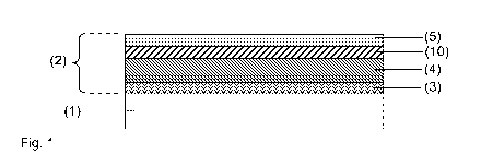
Fig. 1 depicts a cross-section through an embodiment of the pane according to
the
invention with the substrate 1 and the thermal radiation reflecting coating 2
(also called
low-E-coating). The substrate 1 contains soda lime glass and has a thickness
of 2.9
mm. The coating 2 comprises a lower dielectric layer 3, a functional layer 4,
a
darkening layer 10, and an upper functional layer 5. The layers are arranged
in the
order indicated with increasing distance from the substrate 1.
The functional layer 4 is made of indium tin oxide (ITO) and has a thickness
of roughly
100 nm. The lower dielectric layer 3 and the upper dielectric layer 5 can be
configured
in a manner known per se to the person skilled in the art and can, for
example, be
made of silicon oxide (SiO2) or silicon nitride (Si3N4) and have a thickness
of roughly
100 nm.
The darkening layer 10 is made of titanium nitride (TiNx) and has a thickness
of roughly
20 nm. The darkening layer 10 effects a reduction in the transmittance of the
coating 2
in the visible spectral range.
The darkening layer 10 can, alternatively, also be arranged between the lower
dielectric layer 3 and the functional layer 4, or between the substrate 1 and
the lower
dielectric layer 3. The coating 2 can, alternatively, also have a plurality of
darkening
layers 10.
By means of the darkening layer 10, the light transmittance of the coating 2
is reduced.
If the substrate 1 is tinted, the light transmittance through the coating 2 is
further
reduced. Consequently, it is possible to realize very dark panes, for example,
with
transmittance in the visible spectral range of less than 10%. Panes with such
low
transmittance are difficult to produce by means of a tinted substrate alone
because
glasses with such with such heavy tinting are typically not available
commercially. In
contrast to a coating with a transmittance-reducing functional layer (based,
for
example, on nickel, chromium, zirconium, tantalum, or niobium) on a clear
substrate,
production-related layer defects of the coating 2 according to the invention
on a tinted
substrate 1 have a lower contrast. Consequently, layer defects are less
disturbingly
noticeable to the observer. These are major advantages of the present
invention.
Fig. 2 depicts a cross-section through another embodiment of the pane
according to
the invention with the substrate 1 and the thermal radiation reflecting
coating 2. The
CA 02901778 2015-08-19
23
4351-11-28.997
substrate 1 is configured as in Fig. 1. The coating 2 comprises a lower
dielectric layer
3, a darkening layer 10, a functional layer 4, an upper functional layer 5,
and an
antireflection layer 6. The layers are arranged in the order indicated with
increasing
distance from the substrate 1.
The lower dielectric layer 3 is an adhesive layer made of aluminum-doped
silicon
dioxide (Si02:A1) and has a thickness of roughly 30 nm. The functional layer 4
is made
of indium tin oxide (ITO) and has a thickness of roughly 120 nm. The upper
dielectric
layer 5 ist a barrier layer for regulating oxygen diffusion during a
temperature treatment
of the pane. The barrier layer 5 is made of aluminum-doped silicon nitride
(Si3N4:A1)
and has a thickness of roughly 10 nm. The antireflection layer 6 is made of
aluminum-
doped silicon dioxide (Si02:A1) and has a thickness of roughly 40 nm.
The darkening layer 10 between the lower dielectric layer 3 and the functional
layer 4 is
made of titanium nitride (TiNx) and has a thickness of roughly 20 nm. The
darkening
layer 10 effects a reduction in the transmittance of the coating 2 in the
visible spectral
range.
The darkening layer 10 can, alternatively, also be applied in a different
position, for
example, between the functional layer 4 and the upper dielectric layer 5,
between the
upper dielectric layer 5 and the antireflection layer 6, or between the
substrate 1 and
the lower dielectric layer 3. The coating 2 can, alternatively, also have a
plurality of
darkening layers 10.
Fig. 3 depicts a cross-section through another embodiment of the pane
according to
the invention with the substrate 1 and the thermal radiation reflecting
coating 2. The
coating 2 comprises, as in Fig. 2, a lower dielectric layer 3 (adhesive
layer), a
functional layer 4, an upper dielectric layer 5 (barrier layer), and an
antireflection layer
6. The layers 3, 4, 5, and 6 are configured as in Fig. 2. The coating 2
moreover
includes a cover layer 7 above the antireflection layer 6. The cover layer 7
contains, for
example, Ta205 or TiO2 and has a thickness of 10 nm. The cover layer
advantageously
protects the coating 2 against mechanical damage, in particular against
scratching.
The coating 2 further includes three darkening layers 10. The first darkening
layer 10 is
arranged between the substrate 1 and the lower dielectric layer 3. The second
darkening layer 10 is arranged between the lower dielectric layer 3 and the
functional
CA 02901778 2015-08-19
24
4351-11-28.997
layer 4. The third darkening layer 10 is arranged between the functional layer
4 and the
upper dielectric layer 5. The darkening layers 10 are made of TiNx and have
thicknesses between 10 nm and 15 nm. By means of three darkening layers 10
according to the invention 10, the light transmittance is more greatly reduced
than by a
single darkening layer 10, without the advantageous optical properties being
lost as a
result of an excessively thick darkening layer 10.
Fig. 4 depicts a cross-section through a pane according to the invention with
thermal
radiation reflecting coating 2. The pane is intended as a side window of a
motor
vehicle. The substrate 1 has a thickness of 3.15 mm. The substrate 1 is made
of tinted
soda lime glass and has transmittance of roughly 14% in the visible spectral
range. The
pane is thermally prestressed and bent, as is customary for side windows in
the
automotive sector.
The coating 2 is applied on the interior-side surface of the substrate 1.
There, the
advantageous effect of the coating 2 on the thermal comfort in the interior of
the vehicle
is particularly pronounced. The coating 2 reflects part of the sunlight
incident via the
pane, in particular in the infrared range. The thermal radiation emitted from
the warm
pane in the direction of the vehicle interior is, moreover, at least partially
suppressed as
a result of the low emissivity of the coating 2. Thus, the interior is less
strongly heated
in the summer. In the winter, the thermal radiation emanating from the
interior is
reflected. Consequently, the cold pane acts less strongly as an uncomfortable
heat
sink. Moreover, the necessary heating performance of the climate control
system can
be reduced, which results in significant energy savings.
The coating 2 is preferably applied on the flat substrate 1 before the bending
of the
substrate 1. Coating a flat substrate is technically significantly simpler
than coating a
curved substrate. The substrate 1 is then typically heated to a temperature
from 500 C
to 700 C, for example, 640 C. On the one hand, the temperature treatment is
necessary to bend the substrate 1. On the other hand, the emissivity of the
coating 2 is
regularly improved by the temperature treatment. The upper dielectric layer 5
implemented as a barrier layer influences the extent of oxidation of the
functional layer
4 during the temperature treatment. The oxygen content of the functional layer
4 is
sufficiently low after the temperature treatment that the coating 2 can be
subjected to a
bending process. An excessively high oxygen content would result in damage to
the
CA 02901778 2015-08-19
4351-11-28.997
functional layer 4 during bending. On the other hand, the oxygen content of
the
functional layer 4 is sufficiently high after the temperature treatment for
low emissivity.
The coating 2 is configured as in Fig. 2. The light transmittance through the
pane is
further reduced by the darkening layer 10. The pane with the coating 2 thus
has
transmittance in the visible spectral range of less than 10%. Such dark (rear)
side
windows can be desirable for thermal and/or aesthetic reasons. The darkening
layer 10
according to the invention is suitable due to its corrosion and oxidation
resistance to
withstand the temperature treatment and the bending process undamaged.
Fig. 5 depicts a cross-section through a pane according to the invention with
thermal
radiation reflecting coating 2 as part of a composite pane. The substrate 1 is
bonded to
a cover pane 8 via a thermoplastic intermediate layer 9. The composite pane is
intended as a roof panel for a motor vehicle. The composite pane is curved as
is
customary for panes in the automotive sector. In the installed position of the
composite
pane, the cover pane 8 faces the outside environment and the substrate 1 faces
the
vehicle interior. The interior-side surface of the substrate 1, which faces
away from the
cover pane 8 and the thermoplastic intermediate layer 9, is provided with the
coating 2
according to the invention. The substrate 1 and the cover pane 8 are made of
soda
lime glass and have, in each case, a thickness of 2.1 mm. The thermoplastic
intermediate layer 9 contains polyvinyl butyral (PVB) and has a thickness of
0.76 mm.
The substrate 1, the cover pane 8, and the thermoplastic intermediate layer 9
are
tinted. By means of the coating 2, the light transmittance is further reduced.
Thus, very
dark composite panes can be realized.
Fig. 6 depicts a flowchart of an exemplary embodiment of the method according
to the
invention for producing a pane with thermal radiation reflecting coating 2.
Examples
Panes with thermal radiation reflecting coating 2 were produced according to
the
invention. The precise layer sequence with the materials used and layer
thicknesses of
Examples 1 to 8 are presented in Table 2 and Table 3. The substrate 1 was made
of
tinted soda lime glass and had transmittance in the visible spectral range of
25%. The
darkening layers 10 contained titanium nitride. Titanium nitride has (based on
a solid) a
CA 02901778 2015-08-19
26
4351-11-28.997
melting point of 2950 C and specific electrical resistivity of 20 pohm*cm.
The
examples differ in terms of the number and the thickness as well as the
position of the
darkening layers 10.
In all examples, the substrate 1 was initially flat and was provided with the
coating 2
according to the invention by means of cathodic sputtering. The substrate 1
with the
coating 2 was then subjected for 10 minutes to a temperature treatment at 640
C, bent
in the process, and provided with a radius of curvature of roughly 30 cm.
Table 2
Reference Thickness
Material
Character Example 1 Example 2 Example 3 Example 4
6 Si02:Al 70 nm 70 nm 70 nm 70 nm
TiNx
5 Si3N4:Al 20 nm 20 nm 20 nm 20 nm
2 10 TiNx 5 nm 10 nm 10 nm
4 ITO 120 nm 120 nm 120 nm 120 nm
10 TiNx 5 nm 10 nm 10 nm
3 Si02:Al 35 nm 35 nm 35 nm 35 nm
1 Glass 2.1 mm 2.1 mm 2.1 mm 2.1 mm
CA 02901778 2015-08-19
27
4351-11-28.997
Table 3
Reference Thickness
Material
Character Example 5 Example 6 Example 7 Example
8
6 Si02:Al 70 nm 70 nm 70 nm 70 nm
TiNx 20 nm
5 Si3N4:Al 20 nm 20 nm 20 nm 20 nm
2 10 TiNx 20 nm 20 nm 30 nm
4 ITO 120 nm 120 nm 120 nm 120 nm
10 TiNx 20 nm
3 Si02:Al 35 nm 35 nm 35 nm 35 nm
1 Glass 2.1 mm 2.1 mm 2.1 mm 2.1 mm
The observations on the test panes are summarized in Table 6. Rsquare .s i the
sheet
resistance of the coating 2. TL indicates the transmittance of the panes for
visible light.
RL indicates the reflectivity of the panes for visible light. AL indicates the
absorption of
the panes for visible light. The optical condition of the coating is
influenced, in
particular, by clouding ("haze") as well as cracks.
By means of the coatings 2 according to the invention with the darkening
layers 10, the
transmittance of the pane is further reduced. The temperature treatment during
the
bending of the pane results in a reduction of sheet resistance and, thus, to
reduced
emissivity. The darkening layer 10 is not oxidized, which would result in a
significant
increase in the transmittance TL. The bending process also does not result in
damaging
of the coating such that the optical condition of the layer is good in all
cases.
Comparative Examples
The Comparative Examples differ from the Examples according to the invention
by the
thermal radiation reflecting coating 2. The coatings comprised, as in the
Examples, the
lower dielectric layer 3, the functional layer 4, the upper dielectric layer
5, and the
antireflection layer 6. However, the coatings included no darkening layers 10
according
to the invention. Instead, each coating had two layers made of a material that
did not
satisfy the requirements according to the invention for the darkening layer
(cf. Table 5,
CA 02901778 2015-08-19
28
4351-11-28.997
in which the corresponding melting points Ts and specific electrical
conductivities p are
summarized).
The precise layer sequences with the materials used and layer thicknesses of
the
Comparative Examples 1 to 3 are presented in Table 4. The observations on the
test
panes are summarized in Table 6.
Table 4
Material (Thickness)
Reference Comparative Comparative Comparative
Character Example 1 Example 2 Example 3
6 Si02:Al (70 nm) Si02:Al (70 nm) Si02:Al (70 nm)
Si3N4:Al (20 nm) Si3N4:Al (20 nm) Si3N4:Al (20 nm)
NiCr (10 nm) Ti (10 nm) NiCrN (10 nm)
4 ITO (120 nm) ITO (120 nm) ITO (120 nm)
NiCr (10 nm) Ti (10 nm) NiCrN (10 nm)
3 Si02:Al (35 nm) Si02:Al (35 nm) Si02:Al (35 nm)
1 Glass (2.1 mm) Glass (2.1 mm) Glass (2.1 mm)
Table 5
Ts 1 C p /1.incm
NiCr 1400 100
Ti 1660 43
Table 6
CA 02901778 2015-08-19
29
4351-11-28.997
Before After Temperature Treatment and Bending
Temperature
Treatment
Rsquare TL RSquare RL AL Optical
[Ohm / [%] [Ohm / [%] [%] Condition of
Square] Square the Coating
Example 1 56 20.0 16 22.8 3.6 73.6 good
Example 2 55 15.7 17 18.8 2.8 78.4 good
Example 3 53 20.8 16 22.5 1.5 76.0 good
Example 4 53 19.7 16 22.2 4.9 72.9 good
Example 5 48 16.7 19 18.8 5.2 76.0 good
Example 6 50 11.2 18 13.2 1.7 85.1 good
Example 7 28 13.4 16 15.8 0.6 83.6 good
Example 8 47 15.6 21 18.9 0.8 80.3 good
Comparative 5.9
35 12 6.9 5.4 unacceptable
Example 1 87.7
Comparative 14.6
52 18 25.8 6.0 unacceptable
Example 2 68.2
Comparative 6.7
44 25 6.6 9.8 unacceptable
Example 3 83.6
The darkening layers not according to the invention made of NiCr, Ti, or NiCrN
are
damaged by the temperature treatment with the bending process such that the
optical
condition of the coating was in all cases unacceptable for customers in the
automotive
sector. In addition, in particular the absorber layers made of Ti are not
sufficiently
oxidation resistant, so they have, after the temperature treatment,
significantly
increased transmittance TL.
From Table 6, it is furthermore discernible that, in particular, transmittance
can be
influenced by the thickness of the darkening layers 10. This yields the
preferred ranges
for the thickness of the darkening layer 10.
By means of the darkening layers 10 according to the invention, a reduction in
the
transmittance of the thermal radiation reflecting coating is achieved. The
darkening
CA 02901778 2015-08-19
4351-11-28.997
layers 10 are sufficiently corrosion and oxidation resistant to withstand a
temperature
treatment and a bending process without damage. This result was unexpected and
surprising for the person skilled in the art.
List of reference characters:
(1) substrate
(2) thermal radiation reflecting coating
(3) lower dielectric layer
(4) functional layer
(5) upper dielectric layer
(6) antireflection layer
(7) cover layer
(8) cover pane
(9) thermoplastic intermediate layer
(10) darkening layer