Note: Descriptions are shown in the official language in which they were submitted.
CA 02901889 2015-08-26
=
MASK LENS DESIGN AND METHOD FOR PREVENTING
AND/OR SLOWING MYOPIA PROGRESSION
BACKGROUND OF THE INVENTION
[0001] Field of the Invention
[0002] The present invention relates to ophthalmic lenses, and more
particularly,
to contact lenses designed to slow, retard, or prevent myopia progression. The
ophthalmic lenses of the present invention comprise mask lens designs that
provide
improved foveal vision correction, increased depth of focus (DOF), and an
optimized
retinal image at a range of accommodative distances that makes the degradation
of
retinal image quality less sensitive to blur during near work activities,
thereby preventing
and/or slowing myopia progression.
[0003] Discussion of the Related Art
[0004] Common conditions which lead to reduced visual acuity include
myopia
and hyperopia, for which corrective lenses in the form of spectacles, or rigid
or soft
contact lenses, are prescribed. The conditions are generally described as the
imbalance between the length of the eye and the focus of the optical elements
of the
eye. Myopic eyes focus in front of the retinal plane and hyperopic eyes focus
behind
the retinal plane. Myopia typically develops because the axial length of the
eye grows
to be longer than the focal length of the optical components of the eye, that
is, the eye
grows too long. Hyperopia typically develops because the axial length of the
eye is too
short compared with the focal length of the optical components of the eye,
that is, the
eye does not grow long enough.
[0005] Myopia has a high prevalence rate in many regions of the world. Of
greatest concern with this condition is its possible progression to high
myopia, for
example greater than five (5) or six (6) diopters, which dramatically affects
one's ability
1
CA 02901889 2015-08-26
to function without optical aids. High myopia is also associated with an
increased risk of
retinal disease, cataracts, and glaucoma.
[0006] Corrective lenses are used to alter the gross focus of the eye to
render a
clearer image at the retinal plane, by shifting the focus from in front of the
plane to
correct myopia, or from behind the plane to correct hyperopia, respectively.
However,
the corrective approach to the conditions does not address the cause of the
condition,
but is merely prosthetic or intended to address symptoms. More importantly,
correcting
the myopic defocus of the eye does not slow or retard myopia progression.
[0007] Most eyes do not have simple myopia or hyperopia, but have myopic
astigmatism or hyperopic astigmatism. Astigmatic errors of focus cause the
image of a
point source of light to form as two mutually perpendicular lines at different
focal
distances. In the following discussion, the terms myopia and hyperopia are
used to
include simple myopia or myopic astigmatism and hyperopia and hyperopic
astigmatism
respectively.
[0008] Emmetropia describes the state of clear vision where an object at
infinity
is in relatively sharp focus with the crystalline lens relaxed. In normal or
emmetropic
adult eyes, light from both distant and close objects and passing though the
central or
paraxial region of the aperture or pupil is focused by the crystalline lens
inside the eye
close to the retinal plane where the inverted image is sensed. It is observed,
however,
that most normal eyes exhibit a positive longitudinal spherical aberration,
generally in
the region of about +0.50 Diopters (D) for a 5.0 mm aperture, meaning that
rays
passing through the aperture or pupil at its periphery are focused +0.50 D in
front of the
retinal plane when the eye is focused to infinity. As used herein the measure
D is the
dioptric power, defined as the reciprocal of the focal distance of a lens or
optical system,
in meters.
[0009] The spherical aberration of the normal eye is not constant. For
example,
accommodation (the change in optical power of the eye derived primarily though
2
CA 02901889 2015-08-26
changes to the crystalline lens) causes the spherical aberration to change
from positive
to negative.
[0010] As noted, myopia typically occurs due to excessive axial growth or
elongation of the eye. It is now generally accepted, primarily from animal
research, that
axial eye growth can be influenced by the quality and focus of the retinal
image.
Experiments performed on a range of different animal species, utilizing a
number of
different experimental paradigms, have illustrated that altering retinal image
quality can
lead to consistent and predictable changes in eye growth.
[0011] Furthermore, defocusing the retinal image in both chick and
primate
animal models, through positive lenses (myopic defocus) or negative lenses
(hyperopic
defocus), is known to lead to predictable (in terms of both direction and
magnitude)
changes in eye growth, consistent with the eyes growing to compensate for the
imposed
defocus. The changes in eye length associated with optical blur have been
shown to be
modulated by changes in sclera! growth. Blur with positive lenses, which leads
to
myopic blur and a decrease in scleral growth rate, results in the development
of
hyperopic refractive errors. Blur with negative lenses, which leads to
hyperopic blur and
an increase in scleral growth rate, results in the development of myopic
refractive
errors. These eye growth changes in response to retinal image defocus have
been
demonstrated to be largely mediated through local retinal mechanisms, as eye
length
changes still occur when the optic nerve is damaged, and imposing defocus on
local
retinal regions has been shown to result in altered eye growth localized to
that specific
retinal region.
[0012] In humans there is both indirect and direct evidence that supports
the
notion that retinal image quality can influence eye growth. A variety of
different ocular
conditions, all of which lead to a disruption in form vision, such as ptosis,
congenital
cataract, corneal opacity, vitreous hemorrhage and other ocular diseases, have
been
found to be associated with abnormal eye growth in young humans, which
suggests that
relatively large alterations in retinal image quality do influence eye growth
in human
3
CA 02901889 2015-08-26
subjects. The influence of more subtle retinal image changes on eye growth in
humans
has also been hypothesized based on optical errors in the human focusing
system
during near work that may provide a stimulus for eye growth and myopia
development
in humans.
[0013] One of the risk factors for myopia development is near work. Due
to
accommodative lag or negative spherical aberration associated with
accommodation
during such near work, the eye may experience hyperopic blur, which stimulates
myopia
progression as discussed above.
[0014] Moreover, the accommodation system is an active adaptive optical
system; it constantly reacts to near-objects, as well as optical designs. Even
with
previously known optical designs placed in front of the eye, when the eye
accommodates interactively with the lens+eye system to near objects,
continuous
hyperopic defocus may still be present leading to myopia progression.
Therefore, one
way to slow the rate of myopia progression is to design optics that reduces
the impact of
hyperopic blur on retinal image quality. With such designs, for each diopter
of
hyperopic defocus the retinal image quality is less degraded. In another
sense, the
retina is therefore relatively desensitized to hyperopic defocus. In
particular, DOF and
image quality (IQ) sensitivity may be used to quantify the susceptibility of
the eye to
myopia progression as a result of hyperopic defocus at the retina. An
ophthalmic lens
design with larger DOF and low IQ sensitivity will make the degradation of
retinal image
quality less sensitive to hyperopic defocus, hence slowing down the rate of
myopia
progression.
[0015] In object space, the distance between the nearest and farthest
objects of a
scene that appear acceptably sharp is called depth of field. In image space,
it is called
depth of focus (DOF). With a conventional single vision optical design, a lens
has a
single focal point, with image sharpness decreasing drastically on each side
of the focal
point. With an optical design with extended DOF, although it may have a single
nominal
focal point, the decrease in image sharpness is gradual on each side of the
focal point,
4
CA 02901889 2015-08-26
so that within the DOF, the reduced sharpness is imperceptible under normal
viewing
conditions.
[0016] IQ sensitivity can be defined as the slope of retinal IQ-defocus
curve at an
accommodative demand of 1 to 5 diopters. It indicates how image quality
changes with
defocus. The larger the value of IQ sensitivity, the more sensitive the image
quality is to
defocus error during accommodation.
SUMMARY OF THE INVENTION
[0017] The mask lens design of the present invention overcomes the
limitations
of the prior art by ensuring comparable or better distance vision correction
with an
increased depth of focus and reduced IQ sensitivity, thereby providing myopic
treatment.
[0018] In accordance with one aspect, the present invention is directed
to an
ophthalmic lens for at least one of slowing, retarding or preventing myopia
progression.
An ophthalmic lens comprises a first zone at a center and at least one
peripheral zone
surrounding the center and having a dioptric power that is different than that
at the
center. An opaque mask extends from the outermost peripheral zone, thereby
providing
a power profile having substantially equivalent foveal vision correction to a
single vision
lens, and having a depth of focus and reduced IQ sensitivity that slows,
retards, or
prevents myopia progression.
[0019] In accordance with another aspect, the present invention is
directed to a
method for at least one of slowing, retarding or preventing myopia
progression. An
ophthalmic lens is provided with a power profile having substantially
equivalent foveal
vision correction to a single vision lens and having a depth of focus and
reduced retinal
image quality sensitivity that slows, retards, or prevents myopia progression.
The
power profile comprises a first zone at a center of an ophthalmic lens; at
least one
peripheral zone surrounding the center and having a dioptric power that is
different than
CA 02901889 2015-08-26
at the center; and an opaque mask extending from the at least one peripheral
zone.
Accordingly, the growth of the eye is altered.
[0020] The optical device of the present invention has a mask lens
design. As
set forth herein, it has been shown that a lens design with larger depth of
focus and low
image quality sensitivity will make the degradation of retinal image quality
less sensitive
to hyperopic blur, hence slowing down the rate of myopia progression.
Accordingly, the
present invention utilizes mask lens designs that provide foveal vision
correction, and a
depth of focus and also low image quality sensitivity that treats or slows
myopia
progression.
[0021] The mask lens design of the present invention may also be
customized to
achieve both good foveal vision correction and higher treatment efficacy based
on the
subject's average pupil size.
[0022] The mask lens design of the present invention provides a simple,
cost-
effective and efficacious means and method for preventing and/or slowing
myopia
progression.
BRIEF DESCRIPTION OF THE DRAWINGS
[0023] The foregoing and other features and advantages of the invention
will be
apparent from the following, more particular description of preferred
embodiments of the
invention, as illustrated in the accompanying drawings.
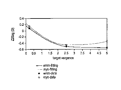
[0024] FIG. 1A, 1B and 1C. Illustrate the change of Defocus Z 2,
Spherical
aberration Z04 terms, and entrance pupil diameter as a function of vergance
for myopic
and emmetropic population.
[0025] FIGS. 2A, 2B, and 2C are illustrations of power profiles for a
spherical
lens, an aspheric lens with +1.50D positive longitudinal spherical aberration
(LSA) at a
6
CA 02901889 2015-08-26
5.0 mm pupil aperture, and an ACUVUEO bifocal lens (a multiconcentric
alternating
distance and near zone lens) with +1.50D add power, respectively.
[0026] FIG. 3A is an illustration of a power profile for a first mask
lens design in
accordance with the present invention.
[0027] FIG. 3B is a graph showing neural sharpness and depth of focus for
the
mask lens design of FIG. 3A.
[0028] FIG. 3C is a graph showing the neural sharpness at various
accommodative states for the mask lens design of FIG. 3A.
[0029] FIG. 4A is an illustration of a power profile for a second mask
lens design
in accordance with the present invention.
[0030] FIG. 4B is a graph showing neural sharpness and depth of focus for
the
mask lens design of FIG. 4A.
[0031] FIG. 4C is a graph showing the neural sharpness at various
accommodative states for the mask lens design of FIG. 4A.
[0032] FIG. 5 is a diagrammatic representation of an exemplary contact
lens in
accordance with the present invention.
DETAILED DESCRIPTION OF THE INVENTION
[0033] FIGS. 2A, 2B, and 2C are illustrations of power profiles for a
spherical
lens, an aspheric lens with +1.50D LSA at 5.0 mm pupil aperture, an ACUVUEO
bifocal
lens with +1.50D add power, respectively. There have been observations that
the
aspheric lens and ACUVUE bifocal lens both may have an effect on slowing
myopia
progression. Thus, a mechanism beyond changing spherical aberration, as
disclosed in
7
CA 02901889 2015-08-26
U.S. Patent No. 6,045,578, is needed for describing lenses for preventing,
treating, or
slowing myopia progression.
[0034] According to the present invention, mask lens designs are
developed for
ophthalmic lenses that provide foveal vision correction, and have an increased
depth of
focus and also reduced IQ sensitivity that treats or slows myopia progression.
[0035] The mask lens designs according to the present invention may be
utilized
with ophthalmic lenses having various different power profiles. In accordance
with one
exemplary embodiment, a mask lens design may be described by:
T2 SA
= PsagH+ 2,1411 x SA x 3.254 12%, x __________
3.252 , r < rMASK (1)
[0036] wherein P represents the dioptric power (D);
r represents a radial distance from a geometric lens center;
SA represents an amount of spherical aberration; and
Pseg(r) represents a step function that has a number of zones with different
magnitudes;
[0037] In accordance with another exemplary embodiment, a mask lens
design
may be described by:
SA
P(r). Ppciiip(r) + 24.43 x SA x12'3.254 3.252 , r < rMASK (2)
wherein P represents the dioptric power (D);
r represents a radial distance from a geometric lens center;
SA represents an amount of spherical aberration; and
Ppcx7p(r) represents a Piecewise Cubic Hermite Interpolating Polynomial curve
control
by number of points. See Fritsch et al., Monotone Piecewise Cubic
Interpolation, SIAM
J. Numerical Analysis, Vol. 17, 1980, pp. 238-46.
8
CA 02901889 2015-08-26
[0038] According to the present invention, the mask may comprise a
pigmented
or tinted opaque region, for example, a colored or black ring. The inner
radius of the
mask, from a center of the lens, may be from about 2.0 mm to 3.0 mm and may
extend
to an outer optical zone of the lens, for example, to about 8.0 mm. In
specific
embodiments, the mask may have a width of 2.25 mm to 4.5 mm.
[0039] To measure vision correction, neural sharpness at 4.5 mm EP
(entrance
pupil) and 6.5 mm EP is utilized as a determinant of retinal image quality. It
is important
to note that any other suitable means and/or methods (for example, area under
the MTF
curve, Strehl ratio, and the like) that measure the goodness of retinal image
quality may
be utilized.
[0040] Neural sharpness is given by the following equation:
r psf
(x,y) gN (x,y)dx dy
[0041] NS = (3)
.00 =CCI
I psf DL (x,y) gN (x,y)dx dy
[0042] wherein psf or point-spread function is the image of a point
object and is
calculated as the squared magnitude of the inverse Fourier transform of the
pupil
function P(X ,Y) where P(X ,Y) is given by
[0043] P(X,Y) = A (X,Y) exp (ik W(X,Y) ), (4)
[0044] wherein k is the wave number (2rr/wavelength) and A(X , Y) is an
optical
apodization function of pupil coordinates X ,Y, psfu is the diffraction-
limited psf for the
same pupil diameter, and gN (X ,Y) is a bivariate-Gaussian, neural weighting
function.
For a more complete definition and calculation of neural sharpness see Thibos
et al.,
Accuracy and precision of objective refraction from wave front aberrations,
Journal of
Vision (2004) 4, 329-351, which discusses the problem of determining the best
9
CA 02901889 2015-08-26
correction of an eye utilizing wave front aberrations. The wave front W(X, Y)
of the
contact lens and the eye is the sum of each as given by:
[0045] WCL + eye (X, Y) WDL(X, Y) + Weye (X, Y). (5)
[0046] To determine image quality (IQ) sensitivity or slope of a lens+eye
system
for an object at a specific target vergence, three major steps are required:
identification
of coupling effect of ocular accommodation system, estimation of the
corresponding
accommodating state for the object, and calculation of the image quality
sensitivity:
[0047] Step 1: Identification of coupling effect of ocular accommodation
system:
As the human eye accommodates from distance to near, two ocular structures
change
simultaneously: the iris aperture becomes smaller; the crystal lens becomes
bulkier.
These anatomical changes leads to three optical related parameters change in a
coupled manner in the lens+eye system: entrance pupil diameter, defocus (e.g.
Zernike
defocus Z20), and spherical aberration (e.g. Zernike spherical aberration
Z40). Note in
particular, since the pupil size decreases as the target moves closer and
conventional
Zernike defocus and spherical aberration highly depends on the pupil sizes, it
is
challenging to specify the these Zernike aberration terms in a conventional
manner. As
an alternative, to gauge the Zernike defocus and aberration across different
pupil sizes,
these terms were sometimes presented in a 'diopter' manner. To convert to the
classic
Zernike coefficients via equations as follows:
z20microns _ 7
z-20Diopter *.(EpD/2)2/(4,,,i3)
ztomicrons. 7
z-40Diopter *(E m)4/(24*.vr5)
wherein EPD is the diameter the entrance pupil, Z20Diopter (unit: D) and
z40Diopter (unit:
Dimm2), note sometimes in the figures, as well as in some literatures, the
unit of this
term is also specified as 'D' in short) are the Zernike defocus and spherical
aberration
terms specified in idiopter manner, and Zaricrons and omicrons are
corresponding
conventional Zernike terms.
Ghosh et al 2012 (Axial Length Changes with Shifts of Gaze Direction in Myopes
and
Emmetropes, IOVS, Sept 2012, VOL. 53, No.10) measured the change of these
three
CA 02901889 2015-08-26
parameters in relation to target vergence for emmetropes and myopes. FIG. 1A,
is a
graphical representation of defocus vs. target vergence, FIG. 1B, is graphical
representation of Spherical Aberration vs. Target vergence and FIG. 1C, is a
graphical
representation of enterance pupil diameter vs. target vergence. As the target
vergence
changes, these three parameters change simultaneously. Since these data were
measured on the human subject eyes without contact lens, the relation between
these
optical parameters and target vergence with lens+eye system differs.
Nevertheless the
coupling relation among the optical parameters (entrance pupil size, defocus,
and
spherical aberration) remains the same because their changes originate from
the same
anatomical source. Different interpolation techniques could then be used to
model such
coupling relations among the three parameters from the experimental data.
[0048] Step 2: Estimation of the corresponding accommodating state for
the
object at near: Once the coupling relation among the entrance pupil, defocus
and
spherical aberration during the accommodation is modeled at step 1, it could
then be
used to estimate the resting accommodating state of lens+eye system for a
target at
any given distance. The scientific essence of this step is to find how the eye
accommodates to the near target in the presence of contact lens. For example,
a target
at specific distance at near (e.g. 2D) results blurs for a distance corrected
lens+eye
system (e.g. the system that combines the lens in Fig.3A and an eye model
0.06D/mm2
SA). To determine the resting accommodating state of this system, the entrance
pupil,
defocus, and spherical aberration of the eye were systematically adjusted per
the
coupling model in step1 so that the corresponding image quality improves to a
threshold. For example in Fig. 3C, the entrance pupil, defocus, and spherical
aberration
are found to be 4.5mm, 1.3D, 0.04D/mm2 to boost the image quality (NS) to be -
1.6
(roughly 20/25 VA).
[0049] Calculation of the image quality sensitivity for the specific
target vergence:
Once the accommodating state, and the corresponding entrance pupil, defocus,
and
spherical aberration are determined, the retina image quality sensitivity or
slope could
be readily calculated as follows:
11
CA 02901889 2015-08-26
[0050] IQ sensitivity = d.NS/d.Rx , (6)
[0051] wherein d.NS/d.Rx is the derivative of neural sharpness to defocus
value.
For example, for design 3A with the standard eye model and target 2D away, the
corresponding IQ sensitivity is calculated to be 0.7.
[0052] By setting ranges for the number of zones, width of the zones,
magnitudes
of the zones, spherical aberration, and radius values in Equation (1),
different power
profiles can be obtained. Exemplary ranges of these variables are listed below
in Table
1.
TABLE 1
Zone1 Zone2 Zone3
Zone1 Zone2 Zone3 SA
Width(mm) Width(mm) Width(mm) mag mag mag (Dimm2) rmask
0)) (D)
max 1.0 1.0 0.5 0.5 0 0.5 0 3
min 0.5 0.5 0 0 -0.5 - 0 -0.5
2
[0053] A resulting multifocal power profile is illustrated in FIG. 3A.
The
parameters for a first mask lens design are listed below in Table 2.
TABLE 2
Zone1 Zone2 Zone3
Design Zone1 Zone2 Zone3 SA
# Width(mm) Width(mm) Width(mm) mag mag
mag (Dimm2) rmask
(D) (D) (D)
FIG. 0.95 0.86
0.46 0.32 -0.23 0.44 -0.16 2.25
2A
[0054] FIG. 3A shows a power profile having a three-zone design, which is
stepped or discontinuous, and a mask. In FIG. 3B, image quality (as measured
by
12
CA 02901889 2015-08-26
neural sharpness) would be sharpest at 0.00 diopter defocus, indicating that
the optic
system carries the sharpest image when it is well focused. As refractive error
(both
positive and negative) is introduced into the optical system, the image
quality starts to
drop. A threshold of neural sharpness value is chosen to quantify DOF at -2.2.
When
the value is larger than -2.2, patients still have reasonably good near vision
for reading.
In FIG. 3B, a horizontal threshold line at -2.2 is drawn. The line intersects
the through-
focus curve. The width between the two intersections corresponds to DOF. In
this
embodiment, the DOF is 1.22D.
[0055] With reference to FIG. 3C, a graph is illustrated of neural
sharpness at 2D,
3D, 4D and 5D accommodative states (target vergence) and a calculated defocus
error
of -0.20D to -0.70D, which is typically associated with accommodation lag, for
the lens
design of FIG. 3A. Each curve is characterized by a shoulder at a threshold
value of
-1.6, having a specific defocus (Z20), spherical aberration (Z40) and Entrance
Pupil size
(EP). The slope of the shoulder is indicative of reduced IQ sensitivity. In
this
embodiment, the IQ sensitivity is 0.66, 0.40, 0.28 and 1.68, respectively.
[0056] Based upon the number of points, spherical aberration, height (D
input
into PPCHIP), and radius values entered into Equation (2), different power
profiles are
obtained. The power profile may be continuous, that is having smooth
transitions
between different powers in different regions of a lens, that is, there are no
abrupt or
discontinuous changes between different zones or regions of the lens.
[0057] Exemplary values of these variables are listed in Table 3 for a
second
mask lens design having a power profile as illustrated in FIG. 4A.
13
CA 02901889 2015-08-26
TABLE 3
SA: -0.06 Dimm2 rmask = 2.25mm
Point # 1 2 3 4 5
Radial
Location(mm) 0 0.56 1.13 1.69 2.25
PPCHIP (D) -0.67 1.00 0.11 -0.07 0.28
[0058] FIG. 4A shows a power profile having a continuous freeform design
and a
mask. As shown in FIG. 4A, the power in the center of the lens is 0.00 D to
0.50D more
negative than a paraxial power of the lens (-3.00D). The power then increases
progressively from the center to a high point. The magnitude of the high point
is 1.00D
to 1.50D more positive than the paraxial power. The location of the high point
A is 0.25
mm to 0.50 mm away from the center. The power drops from a high point to a low
point. The power at the low point is 0.00D to 0.25 D more negative than the
paraxial
power. After the low point, the power increases at a slower rate to an inner
radius of the
mask. The magnitude of such increment is less than 0.25D.
[0059] With reference now to FIG. 4B, a horizontal threshold line for
neural
sharpness is drawn at -2.2. The line intersects the through-focus curve. The
width
between the two intersections corresponds to DOF. In this embodiment, the DOF
is
1.17D.
[0060] With reference to FIG.4C, a graph is illustrated of neural
sharpness at 2D,
3D, 4D and 5D accommodative states (target vergence) and a calculated defocus
error
of -0.60D to -0.70D, which is typically associated with accommodation lag, for
the lens
design of FIG. 4A. Each curve is characterized by a shoulder at a threshold
value of -
1.6, having a specific defocus (Z20), spherical aberration (Z40), and Entrance
Pupil size
(EP). The slope of the shoulder is indicative of reduced IQ sensitivity. In
this
embodiment, the IQ sensitivity is 0.70, 0.52, 0.35 and 0.20, respectively.
14
CA 02901889 2015-08-26
[0061] As shown below in Table 4, neural sharpness at entrance pupil of
4.5 mm
and 6.5 mm are calculated for the mask lens designs. The depth of focus (DOF)
and IQ
sensitivity are calculated at threshold neural sharpness values of -2.2 and -
1.6,
respectively.
TABLE 4
Neural Neural IQ IQ IQ IQ
Depth
Sharpness Sharpness Sensitivity Sensitivity Sensitivity
Sensitivity
of
4.5 mm 6.5 mm at 2D at 3D at 4D at
5D
Focus
EP EP vergence vergence vergence vergence
Sphere -0.4 -0.54 0.76 8.15 5.98 4A3
3.75
Aspheric -0.88 -1.62 1.16 1.10 1.31 3.91
5.62
ACUVUE
-1.34 -2.01 0.89 2.79 2.41 0.76
025
bifocal
Design #1
-0.47 NA 1.22 0.66 0.40 0.28
1.68
FIG. 3A
Design #2
-0.34 NA 1.17 0.70 0.52 0.35
0.20
FIG. 4A
[0062] As shown in Table 4, the mask lens designs as illustrated in FIGS.
3A and
4A, have better neural sharpness than the aspheric and ACUVUE bifocal +1.50
add
lenses at EP 4.5 mm and comparable depth of focus and a superior myopia
treatment
efficacy to the aspheric lens as measured by the depth of focus and reduced IQ
sensitivity, as illustrated in FIGS. 3C and 4C.
[0063] Referring to FIG. 5, there is illustrated a diagrammatic view of a
contact
lens 400 in accordance with the present invention. The contact lens 400
comprises an
optic zone 402 and an outer zone 404. The optic zone 402 comprises a first,
central
zone 406 and at least one peripheral zone 408. In the following examples, the
diameter
of the optic zone 402 may be selected to be 8 mm, the diameter of the
substantially
CA 02901889 2015-08-26
circular first zone 406 may be selected to be 4 mm, and the boundary diameters
of an
annular outer peripheral zone 408 may be 5.0 mm and 6.5 mm as measured from
the
geometric center of the lens 400. It is important to note that FIG. 5 only
illustrates an
exemplary embodiment of the present invention. For example, in this exemplary
embodiment, the outer boundary of the at least one peripheral zone 408 does
not
necessarily coincide with the outer margin of the optic zone 402, whereas in
other
exemplary embodiments, they may coincide. The outer zone 404 surrounds the
optic
zone 402 and provides standard contact lens features, including lens
positioning and
centration. In accordance with one exemplary embodiment, the outer zone 404
may
include one or more stabilization mechanisms to reduce lens rotation when on
eye.
[0064] In specific embodiments of the present invention, the mask may
have an
inner radius at any one of the at least one peripheral zones 408 and extend to
the outer
margin of the optic zone 402.
[0065] It is important to note that the various zones in FIG. 5 are
illustrated as
concentric circles, the zones may comprise any suitable round or non-round
shapes
such as an elliptical shape.
[0066] It is important to note that as the entrance pupil size of the eye
and target
vergence/accommodation varies among subpopulations. In certain exemplary
embodiments, the lens design may be customized to achieve both good foveal
vision
correction and myopic treatment efficacy based on the patient's average pupil
size.
Moreover, as pupil size correlates with refraction and age for pediatric
patients, in
certain exemplary embodiments, the lens may be further optimized towards
subgroups
of the pediatric subpopulation with specific age and/or refraction based upon
their pupil
sizes. Essentially, the power profiles may be adjusted or tailored to pupil
size to
achieve an optimal balance between foveal vision correction, and increased
depth of
focus, and reduced IQ sensitivity.
16
CA 02901889 2015-08-26
[0067] Currently available contact lenses remain a cost effective means
for vision
correction. The thin plastic lenses fit over the cornea of the eye to correct
vision
defects, including myopia or nearsightedness, hyperopia or farsightedness,
astigmatism, i.e. asphericity in the cornea, and presbyopia, i.e., the loss of
the ability of
the crystalline lens to accommodate. Contact lenses are available in a variety
of forms
and are made of a variety of materials to provide different functionality.
[0068] Daily wear soft contact lenses are typically made from soft
polymer
materials combined with water for oxygen permeability. Daily wear soft contact
lenses
may be daily disposable or extended wear disposable. Daily disposable contact
lenses
are usually worn for a single day and then thrown away, while extended wear
disposable contact lenses are usually worn for a period of up to thirty days.
Colored
soft contact lenses use different materials to provide different
functionality. For
example, a visibility tint contact lens uses a light tint to aid the wearer in
locating a
dropped contact lens, enhancement tint contact lenses have a translucent tint
that is
meant to enhance one's natural eye color, the color tint contact lens
comprises a
darker, opaque tint meant to change one's eye color, and the light filtering
tint contact
lens functions to enhance certain colors while muting others. Rigid gas
permeable hard
contact lenses are made from siloxane-containing polymers but are more rigid
than soft
contact lenses and thus hold their shape and are more durable. Bifocal contact
lenses
are designed specifically for patients with presbyopia and are available in
both soft and
rigid varieties. Toric contact lenses are designed specifically for patients
with
astigmatism and are also available in both soft and rigid varieties.
Combination lenses
combining different aspects of the above are also available, for example,
hybrid contact
lenses.
[0069] It is important to note that the mask lens design of the present
invention
may be incorporated into any number of different contact lenses formed from
any
number of materials. Specifically, the mask lens design of the present
invention may be
utilized in any of the contact lenses described herein, including, daily wear
soft contact
lenses, rigid gas permeable contact lenses, bifocal contact lenses, toric
contact lenses
17
CA 02901889 2015-08-26
and hybrid contact lenses. In addition, although the invention is described
with respect
to contact lenses, it is important to note that the concept of the present
invention may be
utilized in spectacle lenses, intraocular lenses, corneal inlays and onlays.
[0070]
Although shown and described is what is believed to be the most practical
and preferred embodiments, it is apparent that departures from specific
designs and
methods described and shown will suggest themselves to those skilled in the
art and
may be used without departing from the spirit and scope of the invention. The
present
invention is not restricted to the particular constructions described and
illustrated, but
should be constructed to cohere with all modifications that may fall within
the scope of
the appended claims.
18