Note: Descriptions are shown in the official language in which they were submitted.
CA 02902195 2015-08-20
WO 2014/165255 PCT/US2014/024991
APPARATUS AND METHOD FOR SINTERING PROPPANTS
Field of Invention
The present invention relates generally to the field of hydraulic fracturing
of subterranean
formations in the earth and, more particularly, to a system, method and
apparatus for sintering
ceramic proppant particles used in the process of hydraulic fracturing of
wells.
Background Art
The United States, as well as many other countries, has an abundant source of
unconventional Oil and Gas resources located in shale formations. Hence, the
term Shale Oil or
Shale Gas. However, these tight shale formations require a unique completion
method, referred
to as hydraulically fracturing, to untrap the oil and/or gas and allow it to
flow to the production
tubing of the well. In order to keep the fractures open, the well must be
propped open with a
high strength material. This is similar to propping a door open with a wooden
wedge or divider.
However, in lieu of wooden wedge or dividers high strength material, such as
frac sand and/or
ceramic beads are pumped into the well and into the fissures formed from
hydraulically
fracturing the well. Proppants are used to "prop" open the oil or gas well
during hydraulic
fracturing of the well. Hence the term "proppant."
Frac sand is traditionally used as the proppant for most hydraulically
fractured wells.
However, the crush strength and spherical shape of frac sand is far inferior
to that of ceramic
proppants. Many Oil and Gas operators have turned to ceramic proppants to
improve the
conductivity or flow of the well after it has been hydraulically fractured.
Due to the inherit
superior spherical shape of ceramic proppants over frac sand, conductivity
(flow) of ceramic
proppants allows for enhanced gas and/or oil flow within the well. This is
crucial for
maximizing flow from the well.
Carbo Ceramics, Inc. manufactures an extensive line of proppants that range
from resin-
coated sand to ceramic proppants. For example, US Patent Application
Publication No. US
2012/20231981 Al, describes various processes for manufacturing proppant
particles.
The major issues associated with the manufacture of ceramic proppants are
cost,
production capacity and emissions. The traditional method for sintering
ceramic proppants uses
long rotary kilns fired with natural gas. First, the construction and
installation of a new rotary
kiln is expensive and requires a long lead-time (e.g., upwards of 18 to 24
months), so capacity
expansion is difficult. Second, if the price of natural gas increases the
production costs increase.
1
CA 02902195 2015-08-20
WO 2014/165255 PCT/US2014/024991
On the other hand, when the price of natural gas decreases, operators tend to
not drill gas wells
and/or use frac sand. As a result, sales decrease for ceramic proppants.
Third, many facilities
utilizing rotary kilns must install expensive scrubbers to reduce air
emissions. Other issues
associated with long rotary kilns are size, footprint, plant location and
regulatory permits. The
combination of these problems causes long lead times and thus hampers a
company's ability to
increase production capacity to keep up with demand of high performance
ceramic proppants as
compared and contrasted to frac sand.
In addition, sintering time within a rotary kiln is exceptionally long in
order to reach a
typical sintering temperature of 2,800 F to 3,000 F. Typical sintering times
range from 30
minutes to over one hour. If temperature creeps beyond the sintering
temperature, the lower
melting point metals and/or minerals within the green proppant tend to melt
and "plate" out
within the kiln. Thus, the rotary kiln must be shutdown, cooled and repaired
and of course
adversely affects the plants production capacity.
Due to the abundance of natural gas and oil from shale plays, there exists a
need for an
alternative means for sintering proppants without using long rotary kilns.
Summary of the Invention
The present invention provides an apparatus for sintering green pellets to
make proppant
particles. The apparatus includes: (a) a vessel having an overflow disposed in
a first end, an
underflow disposed in a second end, a middle portion having a circular cross-
section disposed
between the first end and the second end, and a tangential inlet proximate to
the first end such
that a gas from the tangential inlet flows along a vortex path from the first
end to the second end
of the vessel; (b) a first electrode extending through the overflow and a
second electrode
extending through the underflow, wherein both electrodes are at least
partially disposed within
the vessel, spaced apart from one another, and axially aligned with one
another along a central
axis of the vessel from the first end to the second end; and (c) one or more
feed tubes extending
through the overflow proximate to the first electrode. The electrodes are used
to create an open
electrical arc that sinters or partially sinters the green pellets from the
one or more feed tubes in a
selected temperature range to form the proppant particles as the green pellets
pass between the
electrical arc and the gas flowing in the vortex path and exit the underflow.
In addition, the present invention provides a method for sintering green
pellets to make
proppant particles. An apparatus is provided that includes: (a) a vessel
having an overflow
disposed in a first end, an underflow disposed in a second end, a middle
portion having a circular
2
CA 02902195 2015-08-20
WO 2014/165255 PCT/US2014/024991
cross-section disposed between the first end and the second end, and a
tangential inlet proximate
to the first end; (b) a first electrode extending through the overflow and a
second electrode
extending through the underflow, wherein both electrodes are at least
partially disposed within
the vessel, spaced apart from one another, and axially aligned with one
another along a central
axis of the vessel from the first end to the second end; and (c) one or more
feed tubes extending
through the overflow proximate to the first electrode. A gas is directed into
the tangential inlet
to flow in a vortex path from the first end to the second end of the vessel.
An open electrical arc
is created between the first electrode and the second electrode. The green
pellets are dropped
from the one or more feed tubes, such that the green pellets are sintered or
partially sintered in a
selected temperature range to form the proppant particles as the green pellets
pass between the
electrical arc and the gas flowing in the vortex path and exit the underflow.
The present invention is described in detail below with reference to the
accompanying
drawings.
Brief Description of the Drawings
The above and further advantages of the invention may be better understood by
referring
to the following description in conjunction with the accompanying drawings, in
which:
FIGURE lA is a diagram of an apparatus for sintering proppants in accordance
with one
embodiment of the present invention;
FIGURE 1B is a diagram of vessel that can be used in an apparatus for
sintering
proppants in accordance with another embodiment of the present invention;
FIGURE 2 is a diagram of an apparatus for sintering proppants in accordance
with
another embodiment of the present invention;
FIGURE 3 is a flow chart of a method for sintering proppants in accordance
with another
yet embodiment of the present invention; and
FIGURES 4A and 4B are a block diagrams of various embodiments of a system in
accordance with another yet embodiment of the present invention.
Description of the Invention
While the making and using of various embodiments of the present invention are
discussed in detail below, it should be appreciated that the present invention
provides many
applicable inventive concepts that can be embodied in a wide variety of
specific contexts. The
specific embodiments discussed herein are merely illustrative of specific ways
to make and use
3
CA 02902195 2015-08-20
WO 2014/165255 PCT/US2014/024991
the invention and do not delimit the scope of the invention. The discussion
herein relates
primarily to sintering green pellets to make proppant particles, but it will
be understood that the
concepts of the present invention are applicable to the manufacture or
processing of particles at
high temperatures.
The systems, devices and methods disclosed in U.S. Patent No. 5,832,361; U.S.
Patent
No. 7,422,695; U.S. Patent No. 7,578,937; and U.S. Patent No. 8,088,290 can be
adapted to
sinter proppants as will be described below. The discussion herein focuses on
FIGURE 2 of
these patents, but can be adapted to the other figures of these patents. As a
result, the present
invention is not limited to the vessel shapes shown.
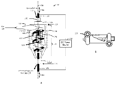
Now referring to FIGURE 1A, an apparatus 100 for sintering green pellets 102
to make
proppant particles 104 in accordance with one embodiment of the present
invention is shown.
The apparatus 100 includes a vessel 106 having an overflow 108 disposed in a
first end 110, an
underflow 112 disposed in a second end 114, a middle portion 116 having a
circular cross-
section disposed between the first end 110 and the second end 114, and a
tangential inlet 118
proximate to the first end 110 such that a gas 120 from the tangential inlet
118 flows along a
vortex path 122 from the first end 110 to the second end 114 of the vessel
106. The interior of
the middle portion 116 of the vessel 106 can be cylindrical shaped (e.g.,
FIGURE 1B), cone
shaped, funnel shaped or a combination thereof Moreover, the interior of the
middle portion
116 of the vessel 106 can be coated or lined with special materials to prevent
heat transfer out of
the vessel 106, change the chemical properties occurring with the vessel or
any other desired
result. The exterior of the vessel 106 can be any shape (see e.g., FIGURE 1B).
In addition, the
vessel 106 can be a cyclone separator, a hydrocyclone, or a gas-sparaged
hydrocyclone. Note
also that, as shown in FIGURE 1B, the underflow 112 at the second end 114 can
be a tangential
outlet, nozzle or other exit configuration.
The apparatus 100 also includes a first electrode 124 extending through the
overflow 108
and a second electrode 126 extending through the underflow 112, wherein both
electrodes 124
and 126 are at least partially disposed within the vessel 106, spaced apart
from one another, and
axially aligned with one another along a central axis 128 of the vessel 116
from the first end 110
to the second end 114. The first electrode 124 and the second electrode 126
are used to create an
electrical arc that produces a wave energy. The wave energy may include
ultraviolet light,
infrared light, visible light, sonic waves, supersonic waves, ultrasonic
waves, electrons,
cavitations or any combination thereof The first electrode 124 and the second
electrode 126 can
4
CA 02902195 2015-08-20
WO 2014/165255 PCT/US2014/024991
be made of carbon or other suitable material. In addition, the first electrode
124 and the second
electrode 126 can be made of a material that coats or chemically reacts with
the green pellets
102. A linear actuator or other device can be used to move the first electrode
124 to and from
the second electrode 126 in order to strike the electrical arc as shown by
arrows 134a. The
second electrode 126 can also be moved using a linear actuator or other device
as shown by
arrows 134b. A DC power source 130 is connected to the first electrode 124 and
the second
electrode 126. In some embodiments, the DC power source 130 can be one or more
batteries or
one or more solar powered batteries.
In addition, the apparatus 100 includes one or more feed tubes 132 extending
through the
overflow 108 proximate to the first electrode 124. As shown in FIGURE 1, the
one or more feed
tubes 132 can be a single tube 132 having a larger diameter than the first
electrode 124 such that
the first electrode 124 is disposed within the single tube 132 and a gap
separates the single tube
132 from the first electrode 124. This configuration synergistically forms a
coaxial tube within a
tube countercurrent heat exchanger. The countercurrent heat exchanger allows
for preheating
the green pellets 102 prior to exposure to the electrical arc. The one or more
feed tubes 132 can
also be a plurality of smaller feed tubes equally spaced around the first
electrode 124. In another
embodiment, the one or more feed tubes 132 are a single smaller feed tube
adjacent to the first
electrode 124. The one or more feed tubes 132 can extend past the first
electrode 124 as shown
in FIGURE 1, or extend proximate to an end of the first electrode 124, or
extend only to a point
before the end of the first electrode 124. A linear actuator or other device
can be used to adjust
the position of the one or more feed tubes 132 as shown by arrows 136. The one
or more feed
tubes 132 can be made of an electrical insulating material, a material that
coats or chemically
reacts with the green pellets 102, or an electrically conductive material to
form one or more third
electrodes. Note also that a liquid can be mixed with the gas 120.
Preferably, the gas 120 is nitrogen because nitrogen is commonly used as a
plasma gas.
But, the gas 120 can be any other gas or combination of gases suitable to
achieve the desired
proppant particles 104. In addition, the green pellets 102 are typically made
from minerals that
commonly include fluoride. When heated within a large rotary kiln fluorine as
well as nitrogen
trifluoride are formed which must be scrubbed prior to emitting exhaust into
the atmosphere.
Not being bound by theory, it is believed that if any halogen species, for
example fluorine and
chlorine reacts with the nitrogen it will be destroyed within the present
invention due to UV
light. U.S. Patent No. 5,832,361 described an apparatus and method for
destroying nitrogen
trichloride (NC13). Likewise, NF3 can be decomposed with UV light and heat.
Hence, water
5
CA 02902195 2015-08-20
WO 2014/165255 PCT/US2014/024991
and/or any scrubbing fluid can be flowed into inlet 11 while nitrogen is added
with the scrubbing
fluid and/or referring to FIGURE 3 of U.S. Patent No. 7,422,695 the porous
tube 14 as gas 15.
Nitrogen can easily be separated from air with an Air Separation Unit ("ASU").
ASU's are very
common within the oil and gas industry. As will be described in reference to
FIGURE 2, using
nitrogen as the gas for the present invention allows for a closed loop
proppants sintering process.
The electrodes 124 and 126 are used to create an open electrical arc that
sinters or
partially sinters the green pellets 102 from the one or more feed tubes 132 in
a selected
temperature range to form the proppant particles 104 as the green pellets 102
pass between the
electrical arc and the gas 120 flowing in the vortex path 122 and exit the
underflow 126. In one
embodiment, the selected temperature range is between about 1,200 C and 3,700
C. The
selected temperature range can be based on a chemical composition of the green
pellets 102, a
size of the green pellets 102, a resonance time of the green pellets 102
within the vessel, or a
combination thereof Note that other parameters may also be used to determine
the selected
temperature range. Note that continually feeding the electrodes 124 and/or 126
allows for
continuous operation. It will be understood that any electrically conductive
material may be
used for the electrode, such as carbon, graphite or copper. The present
invention can also use an
electrode material that can be coated unto the proppants. For example,
titanium is a lightweight
electrically conductive metal that is available in rods, bars or tubes which
can be fed
continuously for coating the proppants with a high strength lightweight metal.
On the other
hand, tungsten is a heavy electrically conductive metal that may be used to
coat proppants.
Green pellets 102 (not sintered proppants 104) are very soft and can easily be
crushed,
shredded and/or comminuted when placed within the vortex or whirling flow of a
cyclone. On
the other hand, the eye of the gas 120 flowing or whirling in the vortex path
moves at a very low
to near zero speed and is, therefore, an ideal feed point for delicate
materials such as green
pellets 102. This allows for rapid sintering of proppants 104 (i.e., seconds
as opposed to 30
minutes or more). The one or more feed tubes 132 drop or feed the green
pellets 102 into the
eye of the gas 120 flowing or whirling in the vortex path. All or part of the
gas may exit through
the overflow 108. Note that the sintering process may involve a single pass
through a single
apparatus 100, or multiple passes through a single apparatus 100, or a single
pass through
multiple apparatuses 100 (FIGURE 4B).
In another embodiment, the apparatus 100 may include a heated gas source
connected to
the one or more feed tubes 132 to pre-heat the green pellets 102. The heated
gas source can be a
6
CA 02902195 2015-08-20
WO 2014/165255 PCT/US2014/024991
high temperature blower, a high temperature compressor, an electrical heater
or heated gas
source, a burner, a thermal oxidizer, a jet exhaust, an oxy-fuel torch, a
plasma torch, an internal
combustion engine exhaust, or a combination thereof
In another embodiment, the vessel 106 also includes a radio frequency source
138 (e.g.,
one or more radio frequency coils, a waveguide, or a combination thereof,
etc.) attached to or
disposed within the vessel 106. The microwave source and/or induction coils
138 can
inductively couple to the plasma utilizing radio frequency in the range of 0.5
kHz to 300 MHz.
The carbon arc may provide the excitation energy for either the microwaves or
RF energy to
couple to and form a global plasma within the eye. However, susceptors may be
located within
the vessel 106 in order to ignite the plasma and allow for coupling and
sustaining the plasma.
Likewise, the inductively coupled plasma is sustained within the eye. The
green pellets 102
drop down the vertical axis of the eye and through the inductively coupled
plasma and are
discharged through the bottom of the vessel 106. Plasma can couple to Radio
Frequency Energy
(e.g., inductively coupled ("IC") plasma torches, etc.). The present
inventor's Plasma Whirl
Reactor is an IC Plasma Torch. The Radio Frequency ("RF") Spectrum ranges from
about 3
kHz to 300 GHz. Induction heating commonly employs RF coils ranging in
frequency from 0.5
kHz to 400 kHz. Likewise, microwave frequencies commonly found in household
microwave
ovens normally operate at 2,450 Mega Hertz (2.450 GigaHertz) and at a power of
300 watts to
1,000 watts. Commercial microwave ovens ranging in power from 6 kw to 100 kw
typically
operate at a frequency of 915 MHz (Mega Hertz).
As previously stated RF energy can couple to a gas and form plasma. Coupling
efficiency is based upon several variables ranging from the gas type, gas flow
rate, frequency,
cavity and/or reactor shape and volume. The three major issues with plasma are
igniting,
sustaining and confining the plasma. Igniting and sustaining plasma with an
electrical arc is
fairly straightforward and simple. DC plasma torches utilize inertial
confinement to maximize
and transfer energy to the work piece. Likewise, plasma confinement is
necessary to prevent
melting of the torch itself However, plasma ignition with RF energy is quite
difficult.
Consequently, many RF torches using an RF coil or a Microwave source typically
employ a
susceptor to ignite the plasma. The susceptor is simply a pointed metal rod
that will absorb the
RF energy, heat up and then emit an electron via thermionic emission. As a
result, the spark
ignites any gases present and forms the plasma. Note that using a DC plasma
torch as the heater
allows for increasing the bulk plasma volume by simply turning on the RF coil
or Microwave
7
CA 02902195 2015-08-20
WO 2014/165255 PCT/US2014/024991
generator and injecting wave energy in the form of photons emitted from the RF
coil or the
Microwave magnetron to enhance the plasma.
Referring now to FIGURE 2, an apparatus 200 for sintering green pellets 102 to
make
proppant particles 104 in accordance with one embodiment of the present
invention is shown.
Apparatus 200 includes the same apparatus 100 as previously described in
reference to FIGURE
1 with the addition of a gas slide 202 and a gas line 204. Optional components
include a gas-to-
gas heat exchanger 206, a hot gas clean up device 208 and/or a gas compressor
210. The gas
slide 202 has a first inlet 212 for the green pellets 102, a second inlet 214
for a feed gas 216 and
an outlet 218 connected to the one or more feed tubes 132. The gas slide 202,
also commonly
referred to as air slides, provide a preferred conveyor for gently feeding
green pellets 102 into
the one or more feed tubes 132. Pneumatic air slides are common and available
from such
vendors as Dynamic Air, WG Benjey and FL Smidth ("Fuller AirslideTM Conveying
Technology"). Other mechanisms (e.g., shaker trays, conveyors, etc.) for
transferring the green
pellets 102 to the one or more feed tubes 132 can be used.
The feed gas 216 used for the gas slide 202 can be supplied in a variety of
ways, such as
a separate feed gas source 220, or a gas line 204 connecting the overflow 108
to the second inlet
214 of the gas slide 202 such that the feed gas 216 is at least a portion of
the hot gas that exits
the overflow 108. A valve or regulator attached to the gas line 204 can be
used to control a
pressure of the feed gas 216. Moreover, the feed gas 216 can be heated to
preheat the green
pellets 102 using a heater (not shown) or the gas-to-gas heat exchanger 206.
As shown, the gas-
to-gas heat exchanger 206 is connected to the feed gas source 220, the second
inlet 214 of the
gas slide 202 and the gas line 204 such that heat from the hot gas exiting the
overflow 108 is
transferred to the feed gas 216. Note that any gas may be used as the feed gas
216 and it is not
necessary to use the hot gas exiting from the overflow 108.
The heater (not shown) may be selected but is not limited to a group that
includes a high
temperature blower or compressor, electrical heater or heated gas source,
burner, thermal
oxidizer, jet rocket, oxy-fuel torch, plasma torch and/or even the exhaust
from an internal
combustion engine such as a reciprocating engine or gas turbine engine. The
utilization of
engine exhaust allows for generating electricity while sintering proppants.
Hence, a unique
cogenerating system ¨ generating electricity while producing proppants. In
another example, the
heater includes another electrode proximate to inlet 118. For example, the
heater can be the DC
Plasma ArcWhirl Torch disclosed in US Patent Numbers 8,074,439 and 8,278,810
and
8
CA 02902195 2015-08-20
WO 2014/165255 PCT/US2014/024991
7,622,693 and 8,324,523. Likewise, an ideal heater or heated gas source may be
the thermal
oxidizer shown in Figure 6 of US Patent Number 8,074,439 or the plasma rocket
as disclosed in
Figure 7 of US Patent Number 8,074,439.
The gas line 204 can also be used to recirculate at least a portion of the gas
120 that exits
the overflow 108 back into the tangential inlet 118 creating a closed loop or
partially closed loop
process. To enhance efficiency, a hot gas clean up device 208 and/or a gas
compressor 210 can
be attached to the gas line 204 and the tangential inlet 118. Other components
can be added to
the apparatus 200 as will be appreciated by those skilled in the art.
In one embodiment of the present invention, the use of multiple small diameter
vessels
fed from a common header provides for a compact proppant manufacturing plant
or system that
is efficient and scalable. Likewise, this configuration enables the plant to
increase production
capacity via small increments and not through the purchase of one long rotary
kiln or one large
plasma process. The present invention allows the proppants to be manufactured
in a multi-stage
sintering process wherein addition materials can be added to, coated or
reacted with the
proppants to produce new and improved characteristics. Moreover, the ability
to use off-the-
shelf and/or modified high temperature and high pressure cyclones sourced from
the oil and gas
industry as a component for a plasma proppant manufacturing system allows for
a relatively
compact, modular and inexpensive plant that could be built in a timely
fashion. Finally, the
present invention provides a system that can be mounted on a skid, trailer,
truck, rail car, barge
or ship and operated at or near the drilling operation, which greatly reduces
the cost of the
proppants by saving expensive storage and transportation costs.
Now referring to FIGURE 3, a flow chart of a method 300 for sintering green
pellets to
make proppant particles is shown. An apparatus is provided in block 302 that
includes: (a) a
vessel having an overflow disposed in a first end, an underflow disposed in a
second end, a
middle portion having a circular cross-section disposed between the first end
and the second end,
and a tangential inlet proximate to the first end; (b) a first electrode
extending through the
overflow and a second electrode extending through the underflow, wherein both
electrodes are at
least partially disposed within the vessel, spaced apart from one another, and
axially aligned with
one another along a central axis of the vessel from the first end to the
second end; and (c) one or
more feed tubes extending through the overflow proximate to the first
electrode. A gas is
directed into the tangential inlet to flow in a vortex path from the first end
to the second end of
the vessel in block 304. An open electrical arc is created between the first
electrode and the
9
CA 02902195 2015-08-20
WO 2014/165255 PCT/US2014/024991
second electrode in block 306. The green pellets are dropped from the one or
more feed tubes in
block 308, such that the green pellets are sintered or partially sintered in a
selected temperature
range to form the proppant particles as the green pellets pass between the
electrical arc and the
gas flowing in the vortex path and exit the underflow. Other steps may be
provided as is
apparent from the description of the apparatus 100 and 200 above, or will be
apparent to those
skilled in the art.
Referring now to FIGURES 4A and 4B, a block diagrams of various embodiments of
a
system 400 is shown. FIGURE 4A shows a processing system 400a in which the
green pellets
102 are processed (one pass or multiple passes) by each apparatus (100a or
200a; 100b or 200b;
100c or 200c; 100d or 200d) in parallel to produce the sintered proppant
particles 104. System
400a is easily scalable to accommodate increasing/decreasing demand. System
400a can be in a
building or made portable by mounting the system on a skid, trailer, truck,
rail car, barge or ship
402. FIGURE 4B shows a processing system 400b in which the green pellets 102
are processed
by each apparatus (100a or 200a; 100b or 200b; 100c or 200c; 100d or 200d) in
series to produce
the sintered proppant particles 104. Note that system 400b can be setup as a
tower or pancake
arrangement in which the apparatuses are stacked or vertically aligned with
one another. System
400b can be made scalable by disconnecting one or more of the apparatuses to
accommodate
increasing/decreasing demand. System 400b can be in a building or made
portable by mounting
the system on a skid, trailer, truck, rail car, barge or ship 402.
The foregoing description of the apparatus and methods of the invention in
described
embodiments and variations, and the foregoing examples of processes for which
the invention
may be beneficially used, are intended to be illustrative and not for purposes
of limitation. The
invention is susceptible to still further variations and alternative
embodiments within the full
scope of the invention, recited in the following claims.