Language selection

Search

Patent 2903443 Summary

Third-party information liability

Some of the information on this Web page has been provided by external sources. The Government of Canada is not responsible for the accuracy, reliability or currency of the information supplied by external sources. Users wishing to rely upon this information should consult directly with the source of the information. Content provided by external sources is not subject to official languages, privacy and accessibility requirements.

Claims and Abstract availability

Any discrepancies in the text and image of the Claims and Abstract are due to differing posting times. Text of the Claims and Abstract are posted:

  • At the time the application is open to public inspection;
  • At the time of issue of the patent (grant).
(12) Patent: (11) CA 2903443
(54) English Title: DIG TUBE FOR VACUUM SYSTEM
(54) French Title: TUBE DE CREUSAGE POUR SYSTEME D'ASPIRATEUR
Status: Granted and Issued
Bibliographic Data
(51) International Patent Classification (IPC):
  • E02D 17/00 (2006.01)
  • E21B 07/18 (2006.01)
  • E21B 21/00 (2006.01)
(72) Inventors :
  • VAN BERKEL, CLINT (Canada)
  • JANUARIO, RICARDO (Canada)
(73) Owners :
  • VAC SAFE SOLUTIONS LTD.
(71) Applicants :
  • VAC SAFE SOLUTIONS LTD. (Canada)
(74) Agent: LAMBERT INTELLECTUAL PROPERTY LAW
(74) Associate agent:
(45) Issued: 2016-11-08
(22) Filed Date: 2015-09-09
(41) Open to Public Inspection: 2016-03-14
Examination requested: 2016-01-13
Availability of licence: N/A
Dedicated to the Public: N/A
(25) Language of filing: English

Patent Cooperation Treaty (PCT): No

(30) Application Priority Data: None

Abstracts

English Abstract

A dig tube for a vacuum system, comprising a tube made from high density polyethylene having a density in the range of 0.93 to 0.97 g/cm3, the tube being connected to a vacuum hose of the vacuum system.


French Abstract

Un tube de creusage dun système d'aspirateur comporte un tube fait de polyéthylène haute densité ayant une densité dans la plage de 0,93 à 0,97 g/cm3, le tube étant connecté à un tuyau d'aspirateur du système d'aspirateur.

Claims

Note: Claims are shown in the official language in which they were submitted.

What is claimed is:
1. A dig tube for a hydrovac system, comprising.
a tube made from high density polyethylene having a density in the range of
0.93 to 0.97
g/cm3, the tube having a first end and a second end, and
the tube being connected to a vacuum hose of the hydrovac system.
2. The dig tube of claim 1 further comprising a flexible boot, the flexible
boot having a boot
end, the boot end extending beyond the first end of the tube.
3. The dig tube of claim 2 in which the flexible boot is made of neoprene.
4. The dig tube of any one of claims 1, 2 and 3, further comprising a
connector, the second end
of the dig tube having a flange, the connector joining the flange of the
second end of the tube to a
flanged end of the vacuum hose.
5. The dig tube of any one of claims 1-4 in which the tube is made of high
density polyethylene
having density 0.9490 g/cc.
6. The dig tube of any one of claims 1-5 in which the tube is made of high
density polyethylene
of one of the following types: PE100, PE4710, PE3408, or PE3608.
7. The dig tube of any one of claims 1-6 in which the tube is made of type
PE100 high density
polyethylene.
8. The dig tube of any one of claims 1-7 in which the tube is made of type
PE4710 high density
polyethylene.
9. The dig tube of any one of claims 1-8 in which the tube has a flanged
end for connecting to
another tube, and the flanged end is tapered, thinning towards an outer
periphery of the flange.
10. The dig tube of claim 9 in which the flanged end has a radiused surface
on the inside corner
of the flange.

Description

Note: Descriptions are shown in the official language in which they were submitted.


CA 02903443 2015-09-09
DIG TUBE FOR VACUUM SYSTEM
TECHNICAL FIELD
[0001] Dig tube for vacuum system, for example hydrovac
system, flusher truck, air vac or
other vacuum systems.
BACKGROUND
[0002] Dig tubes are used in vacuum systems for example to
assist in excavating holes in
the ground, particularly where care must be taken to avoid damage to
underground systems. For
example in a hydrovac or flusher system, water is injected into the ground and
the resulting slurry is
vacuumed up using the dig tube. Dig tubes may be used for example to dig up
pipelines without
causing damage to the pipeline. Applicant proposes a new dig tube.
SUMMARY
[0003] In an embodiment, there is provided a dig tube for a
vacuum system, comprising a
tube made from high density polyethylene having a density in the range of 0.93
to 0.97 g/cm3, the
tube having a first end and a second end, the tube being connected to a vacuum
hose of the vacuum
system.
[0004] In various embodiments, there may be included any one
or more of the following
features: a flexible boot, the flexible boot having a boot end, the boot end
extending beyond the first
end of the tube; the flexible boot being made of neoprene; a reducer
connecting the tube to a flanged
end of the vacuum hose; a flanged end for connecting to another tube, and the
flanged end being
tapered, thinning towards an outer periphery of the flange; and the flanged
end having a radiused
surface on the inside corner of the flange..
[0005] These and other aspects of the device and method are
set out in the claims, which are
incorporated here by reference.
BRIEF DESCRIPTION OF THE FIGURES
[0006] Embodiments will now be described with reference to
the figures, in which like
reference characters denote like elements, by way of example, and in which:
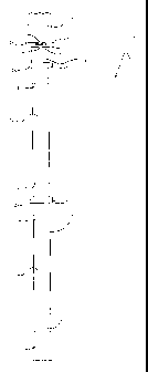
[0007] Fig. 1 is a side view of an embodiment of a dig tube
connected to a vacuum system.
1
1

CA 02903443 2015-09-09
[0008] Fig. 2 is a perspective view of an embodiment of a
dig tube with a boot fitted on an
end of the dig tube.
[0009] Fig. 3 is a perspective view of an embodiment of a
dig tube in which tube segments
are shown disassembled.
DETAILED DESCRIPTION
[0010] Immaterial modifications may be made to the
embodiments described here without
departing from what is covered by the claims. In the claims, the word
"comprising" is used in its
inclusive sense and does not exclude other elements being present. The
indefinite articles "a" and
"an" before a claim feature do not exclude more than one of the feature being
present. Each one of
the individual features described here may be used in one or more embodiments
and is not, by virtue
only of being described here, to be construed as essential to all embodiments
as defined by the
claims.
[0011] As shown in Fig. 1, a dig tube 10 for a vacuum system
has a tube 12 made from high
density polyethylene (HDPE) having a density in the range of 0.93 to 0.97
g/cm3. The density may
for example be 0.9490 g/ cm3. The tube 12 has a first end 14 and an upper end
to which may be
connected a reducer 16. The tube 12 may comprise multiple segments of
connected tubing. The tube
12 is connected to a flanged end 24 of vacuum hose 18 of the vacuum system by
reducer 16 at the
second end of the tube 12. The reducer 16 may be made from steel, which is
conventional, or from
high density polyethylene, as with the dig tube 12.
[0012] HDPE has a large strength-to-density ration, due to
its low amount of branching
which gives it stronger intermolecular forces and tensile strength than low
density polyethylene
(LDPE). HDPE has a higher specific strength than LDPE because the difference
in strength is greater
than the difference in density. HPDE is a thermoplastic material composed of
carbon and hydrogen
atoms joined together forming high molecular weight products. To make HDPE, in
an embodiment,
methane gas is converted into ethylene, then, with the application of heat and
pressure, into
polyethylene. The polymer chain may be 500,000 to 1,000,000 carbon units long.
Short and/or long
side chain molecules exist with the polymer's long main chain molecules. The
longer the main chain,
the greater the number of atoms, and consequently, the greater the molecular
weight. HDPE is also
harder than LDPE and can withstand temperatures of 120 degree Celsius for
short periods.
2
1

CA 02903443 2015-09-09
[0013] The tube 12 may for example be made of HDPE of one or more of the
following
types: PE100, PE4710, PE3408, or PE3608, as designated by the Plastics Pipe
Institute. PE4710 has
a density cell class of 4.
[0014] A protective covering may surround the first end 14 of the tube 12
to protect against
the tube 12 damaging other structures in use. As shown in Figs. 1 and 2, the
protective covering may
for example be a flexible boot 20 having a boot end 22, the boot end 22
extending beyond the first
end 14 of the tube 12 while the vacuum system is in use. The flexible boot 20
helps protect against
the tube 12 causing damage by contact with underground utilities or other
materials in the vicinity of
the vacuum system. The flexible boot 20 may for example by made of neoprene,
and may taper
inwardly, so that its outer circumference extends beyond the tube 12 more than
the inside
circumference, and the inside circumference may be aligned with the square end
of the dig tube 12.
The flexible boot 20 may be bolted to the dig tube or secured in any other
suitable manner.
[0015] As shown in Fig. 1, a flanged end 23 of the reducer 16 may connect
to flanged end
24 of the vacuum hose 18 using a connector. The connector may for example be
any kind of clamp,
and a particular clamp 26 is shown having arms 28, the arms 28 being hingedly
connected and shaped
to hold together the flanged end 24 of the vacuum hose 18 and a flange 23
formed on the reducer 16.
The arms 28 may be tightened around the flanged end 24 of the vacuum house 18
and the flange 23
on the reducer 16 by a hook and lever mechanism. Lower flanged end 36 of the
reducer 16 may be
connected in like manner by another connector 26 to the upper flanged end 38
of the upper piece or
segment of the dig tube 12.
[0016] As shown in Fig. 1, the tube 12 may be formed of multiple tube
segments, for
example a lower tube segment 32 and upper tube segment 34. Each tube segment
may have flaring at
each end, forming flanged ends 38 for connecting to another tube. The flanged
ends 38 may be
tapered, thinning towards an outer periphery of the flange, to provide a
tightly fitting connection
respectively between the lower tube segment 32 and the upper tube segment 34,
between the upper
tube segment 34 and the reducer 16 and between the reducer 16 and the vacuum
hose 18, as shown in
Figs. 1 and 3.
[0017] Fig. 3 shows the lower tube segment 32 and upper tube segment 34,
separated. Each
flanged end 38 may have a radiused surface 39 on the inside corner of the
flange. The radiused
surface 39 may for example have a radius between 0.750 inches and 1.018
inches, or between 0.982
inches and 1.018 inches. Flanged end 23 of reducer 16, shown in Fig. 1, may
also have a similar
radiused surface if the reducer 16 is made of HDPE. A flanged end 38 of a
lower tube segment 32
3

CA 02903443 2015-09-09
and two flanged ends 38 of upper tube segment 34 may be seen in Fig. 3. Each
flanged end may be
connected to provide a secure joint. The flanged ends 38 of each tube segment
may be connected,
such as by a clamp, and in particular by a clamp such as clamp 26.
[0018] The lower tube segment 32 may have a flat end without flaring at
the end that
attaches to the boot 20. The lower tube segment may have a square end, as
shown in Fig. 3.
[0019] As shown in Figs. 1 and 3, each tube segment may have at least one
fusion joint 40
connecting portions of the tube segments for ease of manufacture, or may have
no fusion joints and
be made from a full mould.
[0020] The tube 12 may be orange, black or any other colour. The tube 12
may have a range
of wall thicknesses, for example, a wall thickness between 0.310 and 0.507
inches. The tube may
have a range of outer and inner diameters, such as for example 8.624 inches
outer diameter and 7.549
inner diameter (8 inch tube), or 6.625 outer diameter and 5.799 inner diameter
(6 inch tube) or be
made for other nominal diameters for example 4 inch.
[0021] The tube 12 may be preassembled, with boot 20 already attached.
4

Representative Drawing
A single figure which represents the drawing illustrating the invention.
Administrative Status

2024-08-01:As part of the Next Generation Patents (NGP) transition, the Canadian Patents Database (CPD) now contains a more detailed Event History, which replicates the Event Log of our new back-office solution.

Please note that "Inactive:" events refers to events no longer in use in our new back-office solution.

For a clearer understanding of the status of the application/patent presented on this page, the site Disclaimer , as well as the definitions for Patent , Event History , Maintenance Fee  and Payment History  should be consulted.

Event History

Description Date
Inactive: Office letter 2022-08-26
Inactive: Correspondence - Formalities 2022-07-11
Revocation of Agent Requirements Determined Compliant 2020-04-22
Appointment of Agent Requirements Determined Compliant 2020-04-22
Common Representative Appointed 2019-10-30
Grant by Issuance 2016-11-08
Inactive: Cover page published 2016-11-07
Pre-grant 2016-10-03
Inactive: Final fee received 2016-10-03
Notice of Allowance is Issued 2016-08-26
Letter Sent 2016-08-26
Notice of Allowance is Issued 2016-08-26
Inactive: Approved for allowance (AFA) 2016-08-23
Inactive: Q2 passed 2016-08-23
Amendment Received - Voluntary Amendment 2016-07-13
Inactive: S.30(2) Rules - Examiner requisition 2016-04-13
Inactive: Report - QC passed 2016-04-12
Inactive: Cover page published 2016-03-18
Application Published (Open to Public Inspection) 2016-03-14
Advanced Examination Determined Compliant - paragraph 84(1)(a) of the Patent Rules 2016-03-14
Letter sent 2016-03-14
Letter Sent 2016-02-10
Letter Sent 2016-01-18
Inactive: Office letter 2016-01-18
Letter Sent 2016-01-15
Correct Applicant Request Received 2016-01-13
Early Laid Open Requested 2016-01-13
Inactive: Advanced examination (SO) 2016-01-13
Request for Examination Received 2016-01-13
Request for Examination Requirements Determined Compliant 2016-01-13
Inactive: Advanced examination (SO) fee processed 2016-01-13
All Requirements for Examination Determined Compliant 2016-01-13
Inactive: Single transfer 2016-01-13
Amendment Received - Voluntary Amendment 2016-01-13
Inactive: IPC assigned 2015-10-02
Inactive: First IPC assigned 2015-10-02
Inactive: IPC assigned 2015-10-01
Inactive: Filing certificate - No RFE (bilingual) 2015-09-16
Application Received - Regular National 2015-09-14
Inactive: QC images - Scanning 2015-09-09
Inactive: Pre-classification 2015-09-09
Small Entity Declaration Determined Compliant 2015-09-09

Abandonment History

There is no abandonment history.

Fee History

Fee Type Anniversary Year Due Date Paid Date
Application fee - small 2015-09-09
Request for examination - small 2016-01-13
Registration of a document 2016-01-13
Advanced Examination 2016-01-13
Final fee - small 2016-10-03
MF (patent, 2nd anniv.) - small 2017-09-11 2017-08-03
MF (patent, 3rd anniv.) - small 2018-09-10 2018-07-05
MF (patent, 4th anniv.) - small 2019-09-09 2019-07-11
MF (patent, 5th anniv.) - small 2020-09-09 2020-07-29
MF (patent, 6th anniv.) - small 2021-09-09 2021-09-08
MF (patent, 7th anniv.) - small 2022-09-09 2022-09-02
MF (patent, 8th anniv.) - small 2023-09-11 2023-08-18
Owners on Record

Note: Records showing the ownership history in alphabetical order.

Current Owners on Record
VAC SAFE SOLUTIONS LTD.
Past Owners on Record
CLINT VAN BERKEL
RICARDO JANUARIO
Past Owners that do not appear in the "Owners on Record" listing will appear in other documentation within the application.
Documents

To view selected files, please enter reCAPTCHA code :


To view images, click a link in the Document Description column. To download the documents, select one or more checkboxes in the first column and then click the "Download Selected in PDF format (Zip Archive)" or the "Download Selected as Single PDF" button.

List of published and non-published patent-specific documents on the CPD .

If you have any difficulty accessing content, you can call the Client Service Centre at 1-866-997-1936 or send them an e-mail at CIPO Client Service Centre.


Document
Description 
Date
(yyyy-mm-dd) 
Number of pages   Size of Image (KB) 
Abstract 2015-09-08 1 6
Description 2015-09-08 4 160
Claims 2015-09-08 1 11
Drawings 2015-09-08 3 16
Claims 2016-01-12 1 30
Representative drawing 2016-02-15 1 3
Claims 2016-07-12 1 29
Representative drawing 2016-10-24 1 3
Filing Certificate 2015-09-15 1 178
Acknowledgement of Request for Examination 2016-01-17 1 175
Courtesy - Certificate of registration (related document(s)) 2016-02-09 1 101
Courtesy - Certificate of registration (related document(s)) 2016-01-14 1 101
Commissioner's Notice - Application Found Allowable 2016-08-25 1 164
Reminder of maintenance fee due 2017-05-09 1 112
Maintenance fee payment 2023-08-17 1 26
New application 2015-09-08 3 82
Modification to the applicant/inventor 2016-01-12 12 513
Modification to the applicant/inventor 2016-01-12 5 143
Modification to the applicant/inventor 2016-01-12 5 141
Examiner Requisition 2016-04-12 4 224
Amendment / response to report 2016-07-12 5 154
Final fee 2016-10-02 1 27
Maintenance fee payment 2017-08-02 1 24
Maintenance fee payment 2018-07-04 1 24
Maintenance fee payment 2019-07-10 1 24
Maintenance fee payment 2020-07-28 1 25
Maintenance fee payment 2021-09-07 1 25
Correspondence related to formalities 2022-07-10 3 56
Courtesy - Office Letter 2022-08-25 2 190
Maintenance fee payment 2022-09-01 1 26