Language selection

Search

Patent 2903570 Summary

Third-party information liability

Some of the information on this Web page has been provided by external sources. The Government of Canada is not responsible for the accuracy, reliability or currency of the information supplied by external sources. Users wishing to rely upon this information should consult directly with the source of the information. Content provided by external sources is not subject to official languages, privacy and accessibility requirements.

Claims and Abstract availability

Any discrepancies in the text and image of the Claims and Abstract are due to differing posting times. Text of the Claims and Abstract are posted:

  • At the time the application is open to public inspection;
  • At the time of issue of the patent (grant).
(12) Patent Application: (11) CA 2903570
(54) English Title: FLEXIBLE CONTAINER AND FILLING DEVICE FOR SUCH A FLEXIBLE CONTAINER AND CORRESPONDING FILLING METHOD
(54) French Title: EMBALLAGE FLEXIBLE, ET DISPOSITIF DE REMPLISSAGE POUR UN EMBALLAGE FLEXIBLE DE CE TYPE, ET PROCEDE DE REMPLISSAGE ASSOCIE
Status: Deemed Abandoned and Beyond the Period of Reinstatement - Pending Response to Notice of Disregarded Communication
Bibliographic Data
(51) International Patent Classification (IPC):
  • B65D 30/10 (2006.01)
  • B65B 43/16 (2006.01)
  • B65D 33/02 (2006.01)
(72) Inventors :
  • UNTCH, GUNTER (Germany)
  • KOCH, MARTIN (Germany)
(73) Owners :
  • FLECOTEC AG
(71) Applicants :
  • FLECOTEC AG (Germany)
(74) Agent: MARKS & CLERK
(74) Associate agent:
(45) Issued:
(86) PCT Filing Date: 2014-03-14
(87) Open to Public Inspection: 2014-09-18
Availability of licence: N/A
Dedicated to the Public: N/A
(25) Language of filing: English

Patent Cooperation Treaty (PCT): Yes
(86) PCT Filing Number: PCT/EP2014/055067
(87) International Publication Number: WO 2014140249
(85) National Entry: 2015-09-02

(30) Application Priority Data:
Application No. Country/Territory Date
10 2013 204 602.2 (Germany) 2013-03-15

Abstracts

English Abstract

The invention relates to a flexible container (10.1; 10.2) for sealed connection to a process unit (20), wherein a vacuum is applied to chambers (12, 22) opening into one another. According to the invention, a receptacle for a support apparatus (30.1; 30.2; 30.3) or the support apparatus (30.2) itself is arranged in or on the wall (14.1; 14.3) of the container (10.1; 10.2). The invention further relates to a filling device (30) and a filling method for such a container.


French Abstract

L'invention concerne un emballage (10.1 ; 10.2) flexible destiné à être raccordé de manière étanche à une unité de traitement (20), des espaces (12, 22) débouchant les uns dans les autres étant soumis à l'action d'une dépression. Selon l'invention, un logement destiné à un dispositif de support (30.1 ; 30.2 ; 30.3) ou le dispositif de support (30.2) lui-même est disposé dans ou au niveau de la paroi (14.1 ; 14.3) de l'emballage (10.1 ; 10.2). L'invention concerne en outre un dispositif de remplissage (30) et un procédé de remplissage pour un emballage de ce type.

Claims

Note: Claims are shown in the official language in which they were submitted.

5
Claims:
1. A flexible container (10.1; 10.2) for sealed connection to a process
unit (20),
wherein a vacuum is applied to chambers (12, 22) opening into one another
comprising at least partial volumes of the process unit and the container,
characterized in that
a receptacle for a support apparatus (30.1; 30.2; 30.3), or the support
apparatus
itself (30.2), is disposed in or on the wall (14.1; 14.3) of the container
10.1; 10.2).
2. The flexible container according to Claim 1,
characterized in that
the receptacle for the support apparatus (30,1; 30.2; 30.3) extends in the
circumferential direction and/or in the axial direction, viewed from a
perspective
having an axial direction oriented in the filling direction (E).
3. The flexible container (10.1) according to one of Claims 1 or 2,
characterized in that
the support apparatus (30.3) is an elongated pipe socket, around which the
flexible
container (10.1) can be gathered as a receptacle.
4. The flexible container (10.1; 10.2) according to one of Claims 1 or 2,
characterized in that
the receptacle for the support apparatus (30.1; 30.2) extends in pockets
(16.1; 16.2),
which are formed in or on the wall (14.1;
5. The flexible container (10.1; 10.2) according to one of Claims 1, 2 or
4,
characterized in that
the wall (14.1; 14.2) is designed at least in sections as a double wall, and
that the
wall (14.1; 14.2) is intended to accommodate the support apparatus (30.3)
between
an inner wall (18.1; 18.2) and an outer wall (19.1; 19.2).
6. The flexible container (10.1; 10.2) according to Claims 4 and 5,
characterized in that

6
the pockets (16.1; 16.2) are formed by welding sections of the inner wall
(18.1; 18.2)
to the outer wall (19.1; 19.2) in the circumferential direction or radial
direction.
7. A filling device (30) for a flexible container (10.1; 10.2) having a
support
apparatus (30.1), which may be accommodated in a flexible container (10.1)
according to one of the preceding claims.
8. A filling method for a flexible container (10.1; 10.2) according to one
of Claims
1 through 6, in which the container (10.1; 10.2) can be connected to a process
unit
operated with a vacuum,
characterized in that
a support apparatus (30.1; 30.2; 30.3) holds the container (30.1; 30.2; 30.3)
open
against the forces of the vacuum acting inwardly on the wall (14.1; 14.2) of
the
container (10.1; 10.2).

Description

Note: Descriptions are shown in the official language in which they were submitted.


CA 02903570 2015-09-02
1
Flexible Container and Filling Device For Such a Flexible Container and
Corresponding Filling Method
The invention relates to a flexible container and to a filling device for such
a flexible
container and a corresponding filling method having the features according to
the
preambles of patent claims 1, 7 and 8, respectively.
A device for guiding plastic sacks at a filling station is known from G 88 05
713,
which, however, fails to take into account, or at least does not
satisfactorily take into
account, a vacuum often prevalent in a process unit to be connected to the
container.
The filling process of a flexible container from a process unit to which a
vacuum is
applied fails, in that no material falls into the flexible container, because
known
containers collapse as soon as the vacuum is present. For this reason, to date
flexible containers are not used in such case or can only be used at great
cost and
effort.
Thus, the problem underlying the invention is to propose a flexible container
for
connection to a process unit operating with a vacuum, if possible also a
suitable
filling method and an advantageous filling device.
The problem is solved according to the invention by means of a flexible
container
comprising the characterizing features according to Claim 1, a filling device
according to Claim 7 and a filling method comprising the characterizing method
features of Claim 8.
Advantageous embodiments are specified in the dependent claims.
The flexible container and the process unit comprise chambers opening into one
another, to which a vacuum is applied. The flexible container according to the

1
CA 02903570 2015-09-02
2
invention includes a receptacle for a support apparatus and/or the support
apparatus
itself in or on the wall of the container.
The support apparatus assumes at least in this region, and in advantageous
embodiments far into the inside of the container, a support function from the
inside to
the outside, and counteracts the otherwise imminent collapse.
According to one exemplary embodiment of the container according to the
invention,
the receptacle for the support apparatus extends in the circumferential
direction
and/or in the axial direction, viewed from a perspective having an axial
direction
oriented in the filling direction.
According to another advantageous embodiment of the container according to the
invention, the support apparatus is an elongated pipe socket, around which the
flexible container is gathered. In this arrangement, the entire container
accommodates the support apparatus.
According to another advantageous embodiment of the container according to the
invention, the receptacle for the support apparatus extends in pockets formed
in or
on the wall.
According to another advantageous embodiment of the container according to the
invention, the wall is designed at least in sections as a double wall. The
wall is
intended to accommodate the support apparatus between an inner wall and an
outer
wall.
According to another advantageous embodiment of the container according to the
invention, the pockets are formed by welding sections of the inner wall to the
outer
wall in the circumferential direction or radial direction.
A filling device according to the invention for such a flexible container is
equipped
with a support apparatus, which can be accommodated in the flexible container.

CA 02903570 2015-09-02
3
A filling method according to the invention for such a flexible container
includes the
following method features. The container may be connected to a process unit
operated with a vacuum, and a support apparatus holds the container open
against
the forces of the vacuum acting inwardly on the wall of the container.
The invention is explained in greater detail below with reference to two
exemplary
embodiments depicted in the drawings. The depictions schematically show the
structure and allow views at least sectionwise into the inside of the
components, in
which:
Fig. 1 shows a schematic side view of a first exemplary embodiment of a
flexible container according to the invention, which is connected to a
process unit for filing according to a filling method according to the
invention and is accommodated in a filling device according to the
invention,
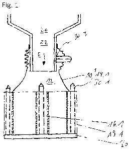
Fig. 2 shows the container from Fig. 1 in a schematic top view, and
Fig. 3 shows a schematic axial section through a second exemplary
embodiment of a container according to the invention.
Figures 1 and 2 are to be understood, in principle, as a side view (Fig. 1)
and a top
view (Fig. 2) depicted in accordance with drafting standards (projection
rule).
Figures 1 and 2 show a first exemplary embodiment of a container 10.1
according to
the invention, which is connected at the top to a process unit 20, to which a
vacuum
is applied, and at the base is accommodated in a filling device 30.
In this arrangement, the flexible container 10.1 according to the first
embodiment
encompasses a first support apparatus 30.3 at the top, namely, a pipe socket
of the
process unit 20 designed of sufficient length, which protrudes further than
normal
into the inside of the container. The solution to the connection problem, in
which
reciprocally interlocking plastic closure strips are used, is particularly
advantageous

CA 02903570 2015-09-02
4
The base of the flexible container according to the first exemplary embodiment
includes axial pockets 16.1, i.e, oriented along a filling direction E, which
accommodate rods of a second support apparatus 30.1, which are distributed
over
the circumference of the container. The pockets 16.1 are formed inside the
wall 14.1.
For this purpose, the wall 14.1 includes an inner well, especially clearly
visible in Fig.
2, which may also be referred to as an inner container, and an outer wall
19.1, which
may be a section of tubular film disposed on the outside. The walls 18,1, 19.1
are
welded together along axial lines. Preferably, polyethylene films are combined
with
one another.
Figure 3 depicts likewise schematically and corresponding more to an axial
section,
a second exemplary embodiment of a flexible container 10.2 according to the
invention. Chamber 12 to be filled in the filling direction E is braced in the
circumferential direction by the support apparatus 30.2 disposed here. For
this
purpose, the support apparatus 30.2, as part of the container 10.2, is
disposed in
circumferential, in particular, spiral-shaped, circumferential pocket(s) 14.2.
When manufacturing a container according to the second exemplary embodiment,
it
is possible in the case of the spiral-shaped configuration to weld the inner
wall 18.2
continuously to the outer wall 19,2.

Representative Drawing
A single figure which represents the drawing illustrating the invention.
Administrative Status

2024-08-01:As part of the Next Generation Patents (NGP) transition, the Canadian Patents Database (CPD) now contains a more detailed Event History, which replicates the Event Log of our new back-office solution.

Please note that "Inactive:" events refers to events no longer in use in our new back-office solution.

For a clearer understanding of the status of the application/patent presented on this page, the site Disclaimer , as well as the definitions for Patent , Event History , Maintenance Fee  and Payment History  should be consulted.

Event History

Description Date
Application Not Reinstated by Deadline 2018-03-14
Time Limit for Reversal Expired 2018-03-14
Deemed Abandoned - Failure to Respond to Maintenance Fee Notice 2017-03-14
Amendment Received - Voluntary Amendment 2016-01-27
Letter Sent 2015-10-14
Inactive: Cover page published 2015-10-05
Inactive: Single transfer 2015-10-01
Inactive: Reply to s.37 Rules - PCT 2015-10-01
Inactive: Request under s.37 Rules - PCT 2015-09-16
Inactive: Notice - National entry - No RFE 2015-09-16
Application Received - PCT 2015-09-15
Inactive: IPC assigned 2015-09-15
Inactive: First IPC assigned 2015-09-15
National Entry Requirements Determined Compliant 2015-09-02
Amendment Received - Voluntary Amendment 2015-09-02
Application Published (Open to Public Inspection) 2014-09-18

Abandonment History

Abandonment Date Reason Reinstatement Date
2017-03-14

Maintenance Fee

The last payment was received on 2015-09-02

Note : If the full payment has not been received on or before the date indicated, a further fee may be required which may be one of the following

  • the reinstatement fee;
  • the late payment fee; or
  • additional fee to reverse deemed expiry.

Please refer to the CIPO Patent Fees web page to see all current fee amounts.

Fee History

Fee Type Anniversary Year Due Date Paid Date
Basic national fee - standard 2015-09-02
MF (application, 2nd anniv.) - standard 02 2016-03-14 2015-09-02
Registration of a document 2015-10-01
Owners on Record

Note: Records showing the ownership history in alphabetical order.

Current Owners on Record
FLECOTEC AG
Past Owners on Record
GUNTER UNTCH
MARTIN KOCH
Past Owners that do not appear in the "Owners on Record" listing will appear in other documentation within the application.
Documents

To view selected files, please enter reCAPTCHA code :


To view images, click a link in the Document Description column. To download the documents, select one or more checkboxes in the first column and then click the "Download Selected in PDF format (Zip Archive)" or the "Download Selected as Single PDF" button.

List of published and non-published patent-specific documents on the CPD .

If you have any difficulty accessing content, you can call the Client Service Centre at 1-866-997-1936 or send them an e-mail at CIPO Client Service Centre.


Document
Description 
Date
(yyyy-mm-dd) 
Number of pages   Size of Image (KB) 
Description 2015-09-02 4 171
Drawings 2015-09-02 2 22
Claims 2015-09-02 2 60
Abstract 2015-09-02 2 83
Representative drawing 2015-09-17 1 9
Cover Page 2015-10-05 1 40
Notice of National Entry 2015-09-16 1 193
Courtesy - Certificate of registration (related document(s)) 2015-10-14 1 101
Courtesy - Abandonment Letter (Maintenance Fee) 2017-04-25 1 172
Prosecution/Amendment 2015-09-02 1 46
International search report 2015-09-02 2 57
Patent cooperation treaty (PCT) 2015-09-02 1 41
National entry request 2015-09-02 3 116
Correspondence 2015-09-16 1 31
Correspondence 2015-10-01 1 35
Amendment / response to report 2016-01-27 6 180