Note: Descriptions are shown in the official language in which they were submitted.
CA 02903894 2015-09-11
COMBINE HEADER REEL APPARATUS FOR SUNFLOWERS
This disclosure relates to the field of agricultural harvesting equipment and
in particular
combine headers for cutting and gathering crop plants.
BACKGROUND
Harvesting sunflowers is facilitated by using specialized header arrangements
on the
front end of a combine to cut the stalks and gather the sunflower heads into
the combine.
Sunflowers grow relatively tall and the seeds are present in a head at the top
of the stalk.
These seed heads are relatively large and heavy, such that when the sunflower
plants are
mature and ready for harvesting the top of the stalks are commonly bent over
with the
heads hanging down and the top portion of the stalk shaped like a hook.
A typical conventional combine header reel has a rotating center shaft mounted
at each
end to the combine header and rotated by a reel drive. A plurality of contact
members are
mounted to the shaft in a horizontal orientation spaced radially from the
shaft. In a
typical reel, the contact members are mounted to the shaft by attaching plates
or arms
perpendicular to the shaft and spaced therealong extending radially from the
shaft and
mounting the contact members to the periphery of the plates or ends of the
arms. The
contact members are configured so that as the shaft and contact members rotate
the
contact members contact standing crop plants and move them rearward into the
cutter bar
and onto the header table where same are gathered into the combine.
These conventional header reels include fixed blade reels and pickup reel. In
a fixed
blade reel the contact members are blades that are fixed to the shaft with a
face oriented
substantially radially, and as the shaft rotates the faces of the blades move
rearward
toward the header and contact the plants as the header moves forward, pushing
the plants
1
CA 02903894 2015-09-11
toward the cutter bar and header table. In a pickup reel the contact members
are
horizontal finger tubes mounted to the shaft by mounting on the periphery of
the plates,
with fingers mounted to the tubes. The fingers pivot about a tube axis so the
angle of the
fingers varies as the reel rotates. The orientation of the fingers is dictated
by a linkage so
the fingers on the bottom portion of the reel always point generally downward
as the reel
rotates, and the fingers act to reach down and pick up crop slightly ahead of
the cutter
bar.
Such a pickup reel is disclosed in United States Patent Numbers 4,156,340 to
Colgan et
al. and 6,502,379 to Snider. United States Patent Number 7,856,801 to
Remillard
discloses a blade conversion for mounting over the fingers of a pickup reel to
in light
crops where the plants are spaced apart and the fingers pass through the
plants instead of
engaging same and sweeping them into the cutter bar. These conventional fixed
blade
and pickup reels are well suited to crops such as cereals, oilseeds, and pulse
crops.
When harvesting sunflowers the contact members contact the stalk somewhat
below the
heads and sweep the stalk into the cutter bar. The stalk is cut off but often
the hook of
the cut off stalk hangs on the contact members with the stalk on one side and
the head
hanging on the other side. As the contact member moves about the rotational
axis the
hook of the stalk simply rotates about the contact member where it is hooked
and remains
hanging as the reel rotates. The head and stalk do not fall onto the header
table but
remain hanging on the blade/bar, tangling with further stalks as the header
moves
forward.
With pickup reels as well, the fingers often spear the sunflower seed heads
and carry
them around as the reel rotates. It is known to mount a cover over the fingers
to make a
flat surface instead of spaced apart fingers to facilitate harvesting
sunflowers.
2
CA 02903894 2015-09-11
Various reels with unconventional configurations have been developed for
harvesting
sunflowers. For example United States Patent Number 4,445,314 to Gust
discloses a reel
with two curved opposite faces where the rotational axis is at a mid-point of
the faces and
the outer edges are rounded. With the entire reel smooth and rounded in this
manner,
when it rotates to urge sunflower stalks into the combine there is nowhere for
the stalks to
hang. Similarly United States Patent Number 4,589,250 to Faul, Jr. discloses a
tubular
reel with short fingers extending from the tube, and United States Patent
Number
4,255,920 to Janzen discloses a reel with three solid smooth faced blades,
again leaving
nowhere for the stalks and hanging heads to hang.
Significant costs and time are required to remove the conventional fixed blade
or pick-up
reel, which is still required for many crops, and replace it with a reel more
suited to
harvesting sunflowers.
SUMMARY OF THE INVENTION
The present disclosure provides a plant pushing apparatus for a combine header
reel that
overcomes problems in the prior art.
The present disclosure provides an apparatus for mounting on a reel of a
combine header
mounted on a front end of a combine for travel in a forward operating travel
direction to
cut plant stalks, wherein the reel comprises a center shaft rotatably mounted
at each end
thereof to the combine header, a plurality of contact members mounted to the
center shaft
in a horizontal orientation radially spaced from the center shaft, and a drive
operative to
rotate the center shaft such that the contact members below the center shaft
move in a
rearward direction toward the combine header. The apparatus comprises, for
each
contact member, a projecting shield member adapted at an inner portion thereof
for
attachment to the contact member such that an outer edge of the projecting
shield
3
CA 02903894 2015-09-11
member is substantially horizontal and rearward of the contact member, and
such that the
outer edge of the projecting shield member contacts plant stalks and pushes
the plant
stalks toward the combine header ahead of the following attached contact
member.
The apparatus attaches to a conventional pickup or fixed blade reel to
facilitate cutting
sunflower plants. The outer edge of the projecting shield member pushing
against the
bent stalk of a sunflower plant reduces the occurrence of cut sunflower stalks
hanging on
the contact member of the reel with the head of the sunflower on one side and
the stalk on
the other.
DESCRIPTION OF THE DRAWINGS
While the invention is claimed in the concluding portions hereof, preferred
embodiments
are provided in the accompanying detailed description which may be best
understood in
conjunction with the accompanying diagrams where like parts in each of the
several
diagrams are labeled with like numbers, and where:
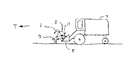
Fig. 1 is a schematic side view of an embodiment of the plant pushing
apparatus of the
present disclosure mounted on the reel of a combine header;
Fig. 2 is a schematic side of the plant pushing apparatus of Fig. 1 where the
reel is a
fixed blade conventional reel;
Fig. 3 is a schematic side view of the projecting shield member of the
embodiment of
Fig. 1 contacting a sunflower plant;
Fig. 4 is a schematic side view of a contact member of a reel of the prior art
contacting
a sunflower plant;
4
CA 02903894 2015-09-11
Fig. 5 is a schematic sectional side view of the embodiment of Fig. 1 mounted
on the
finger tube of a pickup reel and covering the fingers thereof;
Fig. 6 is a schematic sectional side view of the embodiment of Fig. l mounted
on the
fixed blade of a conventional reel;
Fig. 7 is a schematic side view of an alternate embodiment of the plant
pushing
apparatus of the present disclosure mounted directly to the fixed blade of a
conventional reel;
Fig. 8 is a perspective view of a pickup reel of the prior art;
Fig. 9 is a perspective view of the embodiment of Fig. 1, as further
schematically
illustrated in Fig. 5, mounted on the pickup reel of Fig. 8;
Fig. 10 is a schematic side view of the pickup reel and plant pushing
apparatus of Fig.
9..
DETAILED DESCRIPTION OF THE ILLUSTRATED EMBODIMENTS
Figs. 1 - 3 schematically illustrate an embodiment of a plant pushing
apparatus 1 of the
present disclosure for mounting on a reel 3 of a combine header 5 mounted on a
front end
of a combine 7 for travel in a forward operating travel direction T to cut
plant stalks, and
in particular to cut sunflower plants 9. As schematically illustrated in Fig.
2 the reel 3
comprises a center shaft 11 rotatably mounted at each end thereof to the
combine header
5. Fig. 2 schematically illustrates a fixed blade reel 3 with fixed blade
contact members
13 mounted to the shaft 11 in a horizontal orientation radially spaced from
the shaft 11,
5
CA 02903894 2015-09-11
and a drive 15 operative to rotate the shaft 11 such that the contact members
13 below the
shaft move in a rearward direction R toward the combine header 5.
As schematically illustrated in Fig. 3, the apparatus 1 comprises, for each
contact member
13, a projecting shield member 17 adapted at an inner portion 17A thereof for
attachment
to the contact member 13 such that an outer edge 17B of the projecting shield
member 17
is substantially horizontal and rearward of the contact member 13. With this
arrangement
the outer edge 17B of the projecting shield member 17 contacts the sunflower
plants 9
and pushes the plants 9 toward the combine header 5 ahead of the following
attached
contact member 13.
Fig. 4 schematically illustrates a fixed blade contact member 13' of the prior
art
contacting a sunflower plant 9 that includes a stalk 9A, hanging head 9B, and
hook 9C
formed in the stalk 9A. This is a typical sunflower plant when the yield of
the crop is
fairly high and the head 9B is heavy with seeds. It can be seen that the head
9B passes
over the top of the contact member 13' and as the contact member 13' moves
rearward in
direction R the stalk 9A is cut by the knife 19 on the header 5, but with the
head 9B
hanging on a side of the contact member 13' opposite the cut off stalk 9A, the
cut off
sunflower plant 9 often hangs on the contact member 13' as it moves along its
circular
path, rotating on the hook 9C about the contact member 13' as the orientation
changes.
As seen in Fig. 3 the outer edge 17B of the projecting shield member 17 is
ahead of the
contact member 13 and pushes the stalk 9A into the knife 19 so that when the
stalk is cut
the head 9B is still on the same side of the contact member 13 as the stalk 9A
and the
head and stalk fall onto the header 5. The projecting shield member 17 reduces
the
occurrence of the head 9B passing over the top of the contact member 13 and
the hook
9C hanging on the contact member 13.
6
CA 02903894 2015-09-11
Figs. 5 and 9 schematically illustrate an apparatus 1 of the present
disclosure mounted on
a pickup reel 3P, such as is schematically illustrated in Fig. 8, where the
contact member
13P comprises a horizontal finger tube 21 with fingers 23 pivotally mounted to
the tubes
21. The tubes 21 and fingers 23 move in the rearward direction R toward the
header
table. The apparatus 1 comprises a cover 25 configured to attach to the finger
tube 21
and cover a rear side 23R of the fingers, and wherein the projecting shield
member 17 is
adapted at the inner portion 17A thereof for attachment to the contact member
13P by
attachment to the cover 25.
The illustrated cover 25 comprises a sheet assembly comprising a rear sheet
25R
covering at least a portion of the rear side 23R of the fingers 23 and a front
side 25F
covering a portion of a front side 23F of the fingers 25. The front and rear
sheets 25F,
25R are formed by folding a single sheet of material, such as a polyvinyl
chloride
material, over the finger tube 21 and the sheet assembly is then fastened to
the finger tube
25 by fasteners 27 extending between the fingers 23 through corresponding
holes 29 in
the front and rear sheets 25F, 25R. The projecting shield member 17 is adapted
at the
inner portion 17A thereof for attachment to the contact member 13, comprising
the finger
tube 21 and fingers 23, by attachment to the cover 25, such as by rivets 31
extending
through the inner portion 17A of the projecting shield member 17 and the rear
sheet 25R.
A brace 33 may be provided to brace the projecting shield member 17 in the
desired
orientation.
In the illustrated cover 25 the rear sheet 25R extends radially from the
finger tube 21
beyond ends of the fingers 23, and the front sheet 25F extends radially from
the finger
tube 21 to a middle portion of the fingers 23, since the front sheet is only
required to
provide a surface for holding the fasteners 27, and does not contact the
plants 9.
7
CA 02903894 2015-09-11
The outer edge 17B of the projecting shield member 17 is rounded with a radius
greater
than about 0.0625 inches so that same will push the stalk 9B and not cut into
the stalk.
Fig. 6 schematically illustrates the same apparatus 1 mounted on a fixed blade
reel where
the contact member 13 is a fixed blade 35 and wherein the projecting shield
member 17 is
adapted for attachment to the fixed blade 35 by fasteners 27 extending through
corresponding holes 29 in the front and rear sheets 25F, 25R and through the
contact
member.
In the illustrated apparatus 1 the outer edge 17B of the projecting shield
member 17 is
somewhat radially inward from an outer edge of the contact member 13, 13P, and
the
projecting shield member 17 curves from the inner portion 17A thereof
attachable to the
contact member 13, to the outer edge 17B. It is contemplated that this
arrangement will
pass the material smoothly along the face of the projecting shield member 17,
and allow
the outer edge of the contact member 13 to also contact the stalk 9A during
rotation, after
the projecting shield member 17 passes, to push the stalk and attached head 9B
onto the
header 5.
The average diameter of a sunflower head 9B is about eight inches and it is
contemplated
that when attached to the contact member 13, locating the outer edge 17B of
the
projecting shield member 17 rearward of the attached contact member 13 a
distance D, as
schematically illustrated in Fig. 6, that is greater than about eight inches,
or greater than
the average diameter of the sunflower heads 9B, will satisfactorily reduce the
occurrence
of the hooks 9C of the plants 9 hanging on the contact members 13.
Fig. 7 schematically illustrates an alternate apparatus 101 mounted on a reel
where the
contact member 113 is a fixed blade 135 and wherein the projecting shield
member 117
is adapted for attachment to the fixed blade 135 by fasteners 127 extending
through
8
CA 02903894 2015-09-11
corresponding holes 129 in the inner portion 117B of the projecting shield
member 117
and through the fixed blade 135.
Fig. 10 schematically illustrates a side view of a pickup reel 3P with the
plant pushing
apparatus 1 attached to the contact members 13P. hi a fixed blade reel 3 such
as
illustrated in Figs. 2 and 3 the blade contact members 13 are at all times
oriented radially
with respect to the rotational center of the reel. In a pickup reel 3P such as
illustrated in
Fig. 10 the orientation of the fingers 23 changes as the reel rotates so that
at the bottom of
the circle of rotation the fingers 23 are oriented more upright. This upright
orientation
moves the outer edge 17B of the projecting shield member 17 farther rearward
of the tube
21 compared to the fixed blade reel shown in Fig. 3, such that the stalk 9A is
pushed
farther away from the tube 21 and the incidence of the head 9B and hook 9C of
the
sunflower plants 9 hanging on the tube 21 is further reduced.
The disclosed apparatus 1, 101 with the projecting shield member 17, 117
reduces the
occurrence of the sunflower heads 9B passing over the top of the contact
members 13,
13P, 113 with the head 9B on one side of the contact member 13, 113 and the
stalk 9A on
the other, and the hook 9C hanging on the contact members 13, 113.
The foregoing is considered as illustrative only of the principles of the
invention.
Further, since numerous changes and modifications will readily occur to those
skilled in
the art, it is not desired to limit the invention to the exact construction
and operation
shown and described, and accordingly, all such suitable changes or
modifications in
structure or operation which may be resorted to are intended to fall within
the scope of
the claimed invention.
9