Language selection

Search

Patent 2904208 Summary

Third-party information liability

Some of the information on this Web page has been provided by external sources. The Government of Canada is not responsible for the accuracy, reliability or currency of the information supplied by external sources. Users wishing to rely upon this information should consult directly with the source of the information. Content provided by external sources is not subject to official languages, privacy and accessibility requirements.

Claims and Abstract availability

Any discrepancies in the text and image of the Claims and Abstract are due to differing posting times. Text of the Claims and Abstract are posted:

  • At the time the application is open to public inspection;
  • At the time of issue of the patent (grant).
(12) Patent: (11) CA 2904208
(54) English Title: PRESSURIZED GROWING AIR SYSTEM FOR VERTICAL AND HORIZONTAL PLANTING SYSTEMS
(54) French Title: SYSTEME D'AIR DE CROISSANCE PRESSURISE POUR SYSTEMES DE PLANTATION VERTICALE ET HORIZONTALE
Status: Granted and Issued
Bibliographic Data
(51) International Patent Classification (IPC):
  • A01G 09/02 (2018.01)
  • A01G 31/02 (2006.01)
(72) Inventors :
  • PRESCOTT, MARK RANDELL (United States of America)
(73) Owners :
  • AIR8GREEN, LLC
(71) Applicants :
  • AIR8GREEN, LLC (United States of America)
(74) Agent: SMART & BIGGAR LP
(74) Associate agent:
(45) Issued: 2023-10-10
(86) PCT Filing Date: 2014-01-28
(87) Open to Public Inspection: 2014-08-14
Examination requested: 2019-01-09
Availability of licence: N/A
Dedicated to the Public: N/A
(25) Language of filing: English

Patent Cooperation Treaty (PCT): Yes
(86) PCT Filing Number: PCT/US2014/013326
(87) International Publication Number: US2014013326
(85) National Entry: 2015-09-04

(30) Application Priority Data:
Application No. Country/Territory Date
61/849,339 (United States of America) 2013-01-24

Abstracts

English Abstract


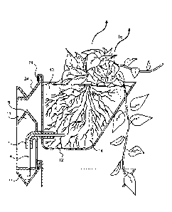
A Growing apparatus for cleansing air and watering plant, wherein the
apparatus
includes a modular panel constructed for either vertical or horizontal
planting systems, including
connecting couplers and end caps for directing water flow from upper to lower
channels. Panel
consist of 5 channels per section with opposing conical top and bottom set at
45 degree angles
(fig.9-23) for both channeling water and accepting irrigation nozzle. System
can also use a
horizontal channel system while the orientation is different but function is
the same. Panels stack
nesting consecutively on top of each other to make larger systems.


French Abstract

L'invention porte sur un système de délivrance d'eau/air pour des plantations verticales et horizontales, lequel système permet une délivrance d'eau, d'air et de chaleur (si nécessaire) par l'intermédiaire d'un système pressurisé unique en association avec une buse de délivrance ciblée conçue pour combiner efficacement de l'air et de l'eau en tandem tout en maintenant de l'humidité de façon adéquate en ligne droite en dessous du sol pour la croissance de plantes et de microbes. Ce système permet à de grands volumes d'air d'être pompés à travers des zones de racines, améliorant le processus de phytoremédiation. Le système peut être mis à l'échelle pour un petit système de croissance pour consommateur et pour de grandes applications commerciales. Ce système élimine la nécessité de bassins de collecte de réservoir/de drainage d'eau séparés, et de détection électronique ou de temporisateurs pour l'arrosage. Ce système économise également de l'énergie, avec des buses ciblées qui délivrent de l'eau, de l'air et de la chaleur facultative à chaque conteneur de croissance. Des buses peuvent être retirées à partir du système quand elles ne sont pas utilisées, de telle sorte qu'aucune énergie ou aucune eau n'est utilisée. Une buse utilise une mèche à absorption, mais ne repose pas sur une action capillaire pour le déplacement de l'humidité, mais utilise à la place un écoulement d'air ciblé directement en dessous de l'extrémité de mèche pour propulser de l'humidité dans un milieu de sol de conteneur de croissance à partir d'une pression « négative » créée à l'intérieur de la buse. Par conséquent, le but de ce système est de délivrer de façon adéquate de l'air et de l'eau, selon un brevet US provisoire 61/849 339, à des racines de plantes pour un nettoyage d'air tout en maintenant de l'eau pour irriguer le système isolée vis-à-vis de l'intérieur d'une pièce.

Claims

Note: Claims are shown in the official language in which they were submitted.


What is Claimed:
1. A growing apparatus for cleansing air and watering a plant comprising:
a modular panel having a rail, a plurality of planting pots, a plurality of
channels including a first channel and a second channel, an air port and a
water
port,
wherein each channel has an opposing conical top and bottom to channel water
and
accept a nozzle having a wick and a recessed air chamber, wherein the nozzle
extends from a respective planting pot to a respective channel, wherein the
air port
is located at the top of at least one respective channel, wherein the water
port is
located at the bottom of at least one respective channel, and wherein the wick
extends into a respective planting pot of the plurality of planting pots; and
an end cap configured to direct water flow from the first channel
to the second channel, wherein said end cap restricts and holds water within
the
first channel and directs water flow to the bottom of the second channel; and
a fan connected to the air port, wherein the fan provides an air flow behind
the wick and a negative pressure of the air flow within the nozzle propels the
water
flow through the wick.
2. The apparatus of claim 1, wherein the nozzle is spaced a distance of 2 to 3
inches above a water level to ensure no mixing of water and air occur.
3. The apparatus of claim 1 wherein, the nozzle directs a volume of air over
an
end of the wick to facilitate water movement into a soil rooting media.
4. The apparatus of claim 1, wherein movement of air through said recessed air
chamber into said nozzle irrigates the plant.
5. The apparatus of claim 1, wherein the air port forces air flow in a
downward
direction to alleviate a mix water and air within the nozzle.
8
Date Recue/Date Received 2022-11-24

6. The apparatus of claim 1, wherein the modular panel comprises a plurality
of
sections and each section of the modular panel consists of five channels per
section.
7. The apparatus of claim 1, wherein an orientation of the plurality of
channels is
horizontal.
8. The apparatus of claim 1, comprising more than one modular panel stacked
vertically.
9. A system for cleansing air and watering a plant comprising:
a modular panel having a rail, a plurality of channels including a first
channel
and a second channel, a fan connected to an air port, a water port connected
to a
water feed, wherein each channel of the plurality of channels has an opposing
conical top and bottom; and
a planting pot hung from the rail, said planting pot seated on a nozzle having
a recessed air chamber and a wick, wherein the fan connected to the air port
provides an air flow behind the wick, wherein the air flow creates negative
pressure
within the nozzle and propels water from the water port and the water feed
through
the nozzle into the planting plot, wherein at least one respective channel
accepts
the nozzle, wherein the air port is located at the top of at least one
respective
channel and wherein the water port is located at the bottom of at least one
respective channel.
10. The system of claim 9, further comprising a pump for directing the water
feed
into the water port, wherein air entering the air port flows downward,
preventing
air and water from mixing in the nozzle.
9
Date Recue/Date Received 2022-11-24

11. The system of claim 9, wherein the first channel is vertically higher than
the
second channel and further comprising end caps configured to direct a flow of
water from the first channel to the second channel.
12. The system of claim 11, wherein the second channel includes a draining
system.
13. The system of claim 11, wherein the nozzle is spaced 2 to 3 inches from
the
water level to ensure no mixing of air and water occurs.
14. A plant growing apparatus comprising:
a body defining a pressurized channel, wherein:
the pressurized channel comprises a top portion and a bottom portion,
and
the bottom portion of the pressurized channel is configured to store
water; a fan configured to introduce air into the top portion of the
pressurized chamber through an air port in communication with the
pressurized chamber;
a wick;
a planting pot; and
a nozzle with a recessed air chamber, the nozzle having (i) a first end in
which the wick is received and (ii) a second end that extends into the
planting pot,
wherein:
a portion of the wick is configured to be submerged in the water, and
the first end of the nozzle is configured to be placed at a distance from
the water
such that introduction of air into the top portion of the pressurized
channel by the fan provides air flow within the nozzle and causes at
least a volume of the water to be transported from the pressurized
channel to the planting pot through the nozzle.
Date Recue/Date Received 2022-11-24

15. The apparatus of claim 14, wherein the distance ranges from 2 to 3 inches
above the volume of the water.
16. The apparatus of claim 14, wherein:
the planting pot is configured to store soil rooting media; and
the nozzle comprises an air channel that is configured to direct a volume of
air from the
pressurized channel to the soil rooting media such that directing the volume
of air
through the air channel facilitates transport of the volume of the water from
the
pressurized channel to the planting pot through the nozzle.
17. The apparatus of claim 16, wherein the transport of the volume of water
from
the pressurized channel through the nozzle irrigates a plant stored in the
planting
pot.
18. The apparatus of claim 14, wherein the fan is configured to introduce air
into
the top portion of the pressurized channel by flowing air in a downward
direction
from the top portion of the pressurized channel to the bottom portion of the
pressurized channel.
19. A system for cleansing air and watering a plant, the system comprising:
a plurality of planting pots;
a panel having a body defining a pressurized channel that is configured to
store water;
an air port in communication with the pressurized channel; and
a fan configured to deliver air into the pressurized channel through the air
port;
wherein the panel comprises:
a plurality of wicks;
11
Date Recue/Date Received 2022-11-24

a plurality of nozzles each having a recessed air channel, wherein each
nozzle has (i) a first end in which is received a wick
from among the plurality of wicks and (ii) a second end that extends into a
planting pot
from among the plurality of planting pots, wherein:
a portion of each wick from the plurality of wicks is configured to be
submerged in the water, and
the first end of the plurality of nozzles is configured to be placed at a
distance from the water such that introduction of air into the pressurized
channel by the fan provides air flow within the plurality of nozzles and
causes
at least a volume of water from the pressurized channel to be transported to
the plurality of planting pots through the plurality of wicks.
20. The system of claim 19, further comprising:
a water port in communication with the panel;
a pump configured to introduce water into the pressurized channel through
the water port.
21. The system of claim 20, further comprising:
a draining system that is configured to remove a volume of water from the
pressurized
channel.
22. The system of claim 19, wherein the distance ranges from 2 to 3 inches
above
the water.
23. The system of claim 19, wherein:
each planting pot included in the plurality of planting pots is configured to
store soil rooting media; and
12
Date Recue/Date Received 2022-11-24

each recessed air channel is configured to direct a volume of air from the
pressurized channel to the soil rooting media such that directing the volume
of air
through the air channel facilitates transport of the volume of the water from
the
pressurized channel to the plurality of planting pots through the plurality of
nozzles.
24. The system of claim 23, wherein the transport of the volume of water from
the
pressurized chamber through the plurality of nozzles irrigates a plurality of
plants
stored in the plurality of planting pots.
25. The system of claim 19, wherein the air port is configured to introduce
air into
the pressurized channel by flowing air in a downward direction from a top
portion of
the pressurized channel to a bottom portion of the pressurized channel.
26. A plant growing apparatus, comprising:
a body defining a pressurized chamber, wherein:
the pressurized chamber comprises a top portion and a bottom
portion, and
the bottom portion of the pressurized chamber is configured to store
water;
a wick defining a volume;
a fan configured to introduce air into the top portion of the pressurized
chamber through an air port in communication with the pressurized chamber;
a planting pot; and
a nozzle having a recessed air channel, wherein the nozzle has (i) a first end
in which the wick is received and (ii) a second end that extends into the
planting
pot, wherein:
a portion of the wick is configured to be submerged in the water, and
the first end of the nozzle is configured to be placed at a distance from
the water such that introduction of air into the top portion of the
pressurized
chamber by the fan provides air flow within the nozzle and causes at least a
13
Date Recue/Date Received 2022-11-24

volume of the water to be transported from the pressurized chamber to the
planting pot through the wick .
14

Description

Note: Descriptions are shown in the official language in which they were submitted.


PRESSURIZED GROWING AIR SYSTEM FOR VERTICAL AND HORIZONTAL
PLANTING SYSTEMS
FIELD OF THE INVENTION
[0001] This invention relates to the field of water and air delivery systems
for plants.
SUMMARY
[0002] The System Pressurized vertical-horizontal growing system solves a
number of
problems that convention irrigation systems have as well as growing systems
for the purpose of
Phytoremediation. Including the elimination of water catch basins,
electronically monitoring
equipment, or the need for specially modified planting mediums. This system
while using a
capillary wick does not require capillary "action" from the wick for moisture
movement, but
relies on air movement to create a "negative" air pressure for drawing water
into the soil sub-
straight. This process created by the air channel location within the wick is
self regulating.
Whereas the more air flow moving through the system the more water movement
thus creating a
balance with the water to air ratio insuring healthy roots and plants without
relying on electronic
equipment. It is also a benefit of the process to create a microclimate and
moisture rich area
around the plant grown, this is accomplished by the movement of air "pushing"
through the soil.
In addition our air flow rates are more favorable to total filtration per pass
of air due to slower
rates. In addition air filtration can be targeted to specific areas where air
remediation is needed.
1
Date recue/ date received 2022-02-18

BACKGROUND
[0003] Indoor green walls using plants have been increasingly popular for
aesthetics,
improved air quality, humidity and natural cooling. Planting system both
horizontal and vertical
systems have been developed for air cleaning using the microbes living around
plant roots for air
cleaning. These green structures can pose a number of problems for the owner,
mold, algae, and
health issues from dirty catch basin reservoir. Drip irrigation or "ebb and
flow" systems are the
most common methods of irrigation for vertical systems. Because each plant
tray drains into the
next consecutive tray all the dirt/debris flows into catch basin that is open
and exposed to the
indoor environment. Poor air circulation creates mold and algae problems, and
poor growing
conditions for the plants. The plants ability to clean the air is inhibited by
these issues and
dramatically reduces the potential healthy effects green walls can have.
Aeroponic systems like
US850523B2 Luebbers, Hensley, use spray methods for watering plants still
resulting in a
mixture of soil and debris in irrigation water which will frequently need to
be cleaned. Drip
vertical systems like patent #EP1416229A2 Darlington, use an air permeable sub-
straight
creating a similar problem of organic/dirt debris building up in containment
reservoir.
EP2654400A 1 Paleszezak discloses a series of pipes, with alternating
prismatic shaped bins, for
air circulation. W02011 019277 A2 Kluiver discloses a system where indoor
pollution is
captured on the leaves of a plant and washed into substrate. System W0201
0033423A 1
Wolverton /Middlemark, use beds with various sized substrate to and drip
irrigation to process
indoor air through. Patent #647780582 Ware uses similar drip methods, again
mixing irrigation
water directly with planting mediums and debris. Therefore it is the purpose
of this invention to
2
Date recue/ date received 2022-02-18

demonstrate an irrigation system that efficiently delivers water and air
directly into planting
substrate that does not need modification for air flow, while keeping
irrigation water separate
from living area. It is the purpose of this invention to use air movement
tofacilitate water
movement over a modified wicking system into the soil, not using the capillary
nature of the
wick to do so as US patent #4 7 41125 Donald Pengorest where a bi expandable
metal control
device is used for control. Further US patent #4219967 Hickerson, relies on a
wick system as
well. Capillary wicks are used in many growing devices however controlling the
moister they
deliver is not easily achieved, leaving soil saturated and unhealthy. There
for it is the purpose of
this invention to control air and moisture delivery through a specifically
designed nozzle that
removes the need for electronic equipment for regulating moisture levels.
BRIEF DESCRIPTION OF DRAWINGS
[0004] Fig. 1 Shows nozzle for vertical system (1) and nozzle with collar (6)
for
positioning nozzle in the correct depth. (2) shows air channel for moving air
through (1) nozzle.
Pot collar (7) holds pot the proper distance from channel. Recessed air
channel (5) ends 1/8-1/4
inch from nozzle opening to insure negative pressure build up in nozzle (1
,2).
[0005] Fig. 2 Shows a straight nozzle (1) for horizontal growing channels with
air
channel (2) and (5) recessed air chamber.
[0006] Fig. 3 Demonstrates the nozzle (1) with fiberglass wick (4) inserted
and (8) air
flow out of tube from channel. Fig 8 (9, 13)to see channel.(5) shows recess in
air chamber to
create the negative pressure on the wick for water movement.
[0007] Fig. 4 Is a front look at nozzle (1) tube end shows the air
channel/chamber (2)
and nozzle end without the fiberglass wick.
3
Date recue/ date received 2022-02-18

[0008] Fig. 5 Demonstrates a straight nozzle (1) for horizontal applications
with which
( 4) nozzle stop (6) and air flow out of nozzle (8).
[0009] Fig. 6 Is a side view of horizontal panel (15) showing nozzles (1)
seated into
channel with which ( 4) hanging in irrigation water (17)1rrigation water needs
to be 2 inches
from base of nozzle (1, 18) for process to work properly.
[0010] Fig. 7 is a front cut away look at a horizontal channel (15) showing
irrigation
water (17) and distance between irrigation water and nozzle base (18).
[0011] Fig. 8 Shows a cross section of air channel (9) with planting pot (12)
pot is
hanging on rail (19) and seated into nozzle (1) wick (4) is hanging in
irrigation water (11) with
the two inch space (18) between the bottom of nozzle ( 1) and irrigation water
( 11) Air and
moisture from channel (9) move into the soil with microbes (14) Clean
remediated air leave
planting pot (12) from top of pot bathing plant in humid air (16). As shown in
Figure 8, the
nozzle extends from a respective planting pot to a respective channel.
[0012] Fig. 9 depicts the embodiment of Fig. 8 having connected chambers that
contain
indoor air and a small reservoir of water.
DETAILED DESCRIPTION
[0013] Water/air delivery system for vertical and horizontal plantings that
enables
water, air and heat (if needed) delivery through a single pressurized system
in conjunction with a
targeted delivery nozzle designed to efficiently combine air and water in
tandem while keeping
soil sub-straight adequately moist for plant and microbe growth . This system
enables High air
volumes to be pumped through root zones enhancing the process of
Phytoremediation. System is
4
Date recue/ date received 2022-02-18

scalable for small consumer growing system and to large commercial
applications. This system
eliminates the need for separate water drainage/reservoir catch basins,
electronic sensing or
timers for watering. This system also conserves energy with targeted nozzles
that deliver water,
air and optional heat to each growth container. Nozzles can be removed from
the system when
not in use so no energy or water will be used. Nozzle uses absorptive wick but
does not rely on
capillary action for moving moisture, rather uses air flow targeted directly
behind wick end to
propel moisture into growing container soil medium from a "negative" pressure
created within
the nozzle. Thus the purpose of this system is to adequately provide air and
water to a US
provisional patent 61/849,339 plants roots for air cleaning while keeping
water for irrigating the
system isolated from rooms interior.
[0014] This system embodies connected chambers (figure 9) that contain indoor
air and
a small reservoir of water(17) and (11) that can either be fed continuously or
intermittingly with
a pump or direct water feed using a solenoid and a timer. Nozzle placement in
the system is
critical (1) and needs to be set into the system so water does not mix with
the nozzle system.
Only air enters the nozzle which in turn creates a negative pressure via the
recessed air channel
(5) which draws the water into the substrate.
[0015] The growing apparatus may be for cleansing air and watering plants,
wherein
the apparatus includes a modular panel constructed for either vertical or
horizontal planting
systems (Fig. 9), including connecting couplers and end caps for directing
water flow from upper
to lower channels (22). For example, a first channel may be located vertically
higher than a
second channel. The second channel may include a drain as discussed in more
detail below. The
panel consist of 5 channels per section with opposing conical top and bottom
set at 45 degree
Date recue/ date received 2022-02-18

angles (23) for both channeling water and accepting irrigation nozzle. Note,
system can also use
a horizontal channel system (as fig.7 and 8 demonstrate) while the orientation
is different they
function is the same. Panels (24) stack nesting consecutively on top of each
other to make larger
systems (Fig.9) Panels may have an attached rail (19) for accepting and
hanging planting
container.
[0016] The panel may have ports for accepting "air" (21) and "water" (20 )
from
external fan or blower as well as drain (26) located at the bottom of the last
run for draining the
system. End connecting caps may extend upwards into the bottom of channel (27)
restricting and
holding water in base of channel as well as channel within the end cap for
directing water flow to
the bottom of next consecutive channel. Air ports (21) at the top of the air
chambers (2) may be
for the purpose of air direction forced in a downward flow to alleviate water
and air "mixing"
within the nozzle. The system creates separation of irrigation water in
channel (11) from soil
substrate (10) by positive pressure within said channel (13) insuring no
mixing of the irrigation
water (11) and planting medium (10) occurs. The system creates separation of
the irrigation
water in channel (11) from the soil sub straight (10) by positive pressure
within said channel
(fig.8-13) insuring that no mixing of the irrigation water (fig.8-11) and
planting medium.
[0017] The system may use a wicking system/nozzle (1) spaced from distance of
2-3
inches from the water level (11) to the base of the nozzle holding wick in
center of channel to
insure no mixing of water and air occur. The nozzle may use a separate air
chamber (2) for
efficiently moving air out of said chamber (28) without extreme pressure build
up. The system
utilizes said nozzle and air chamber (2) that is recessed back 1/8-1/4 inch to
direct air volume
over end of exposed wick to facilitate water movement into soil rooting media
Wherein without
6
Date recue/ date received 2022-02-18

directed air movement over said wick moisture movement would not occur. The
system uses air
movement through said air chamber (2) into said nozzle as a means for
irrigating a plant.
[0018] For example, as shown in Figure 8, the nozzle 1 extends from the
planting pot
12 to the channel 11. More specifically, a first portion of the nozzle 1 and
of the wick 4 is
located in the channel 11 while a second opposite portion of the nozzle 1 and
of the wick 4 is
located in the planting pot. The first portion of the wick 4 may contact water
within the channel
11. As shown in Figures 3 and 4, air flow from the channel 11 may pass through
the nozzle 1,
via the air chamber 2 and recessed air channel 5, into the planting pot 12
(see Figure 8). As
discussed above, this air flow may facilitate moisture movement from the
channel 11 into the
planting pot 12 through the wick 4.
7
Date recue/ date received 2022-02-18

Representative Drawing
A single figure which represents the drawing illustrating the invention.
Administrative Status

2024-08-01:As part of the Next Generation Patents (NGP) transition, the Canadian Patents Database (CPD) now contains a more detailed Event History, which replicates the Event Log of our new back-office solution.

Please note that "Inactive:" events refers to events no longer in use in our new back-office solution.

For a clearer understanding of the status of the application/patent presented on this page, the site Disclaimer , as well as the definitions for Patent , Event History , Maintenance Fee  and Payment History  should be consulted.

Event History

Description Date
Maintenance Request Received 2024-07-29
Maintenance Fee Payment Determined Compliant 2024-07-29
Letter Sent 2024-01-29
Inactive: Grant downloaded 2023-10-19
Grant by Issuance 2023-10-10
Letter Sent 2023-10-10
Inactive: Cover page published 2023-10-09
Inactive: Final fee received 2023-08-22
Pre-grant 2023-08-22
Inactive: Office letter 2023-05-04
Letter Sent 2023-04-24
Notice of Allowance is Issued 2023-04-24
Inactive: Q2 passed 2023-04-05
Inactive: Approved for allowance (AFA) 2023-04-05
Amendment Received - Response to Examiner's Requisition 2022-11-24
Amendment Received - Voluntary Amendment 2022-11-24
Examiner's Report 2022-07-25
Inactive: Report - No QC 2022-06-29
Amendment Received - Response to Examiner's Requisition 2022-02-18
Amendment Received - Voluntary Amendment 2022-02-18
Examiner's Report 2021-10-22
Inactive: Report - No QC 2021-10-18
Amendment Received - Response to Examiner's Requisition 2021-06-11
Amendment Received - Voluntary Amendment 2021-06-11
Examiner's Report 2021-02-12
Inactive: Report - No QC 2021-02-12
Amendment Received - Voluntary Amendment 2020-11-12
Common Representative Appointed 2020-11-07
Examiner's Report 2020-07-14
Inactive: Report - No QC 2020-07-09
Inactive: IPC deactivated 2020-02-15
Inactive: Recording certificate (Transfer) 2019-12-27
Common Representative Appointed 2019-12-27
Inactive: Reply received: Recording fee/docs missing 2019-12-03
Inactive: Office letter 2019-11-15
Common Representative Appointed 2019-10-30
Inactive: Correspondence - Formalities 2019-08-15
Inactive: Office letter 2019-07-22
Inactive: Single transfer 2019-07-11
Letter Sent 2019-01-16
Inactive: First IPC assigned 2019-01-14
Inactive: IPC assigned 2019-01-14
Amendment Received - Voluntary Amendment 2019-01-09
Request for Examination Requirements Determined Compliant 2019-01-09
All Requirements for Examination Determined Compliant 2019-01-09
Request for Examination Received 2019-01-09
Change of Address or Method of Correspondence Request Received 2018-01-12
Inactive: IPC expired 2018-01-01
Inactive: Cover page published 2015-11-13
Amendment Received - Voluntary Amendment 2015-11-06
Inactive: Notice - National entry - No RFE 2015-09-23
Inactive: First IPC assigned 2015-09-21
Inactive: IPC assigned 2015-09-21
Application Received - PCT 2015-09-21
National Entry Requirements Determined Compliant 2015-09-04
Application Published (Open to Public Inspection) 2014-08-14

Abandonment History

There is no abandonment history.

Maintenance Fee

The last payment was received on 2023-02-10

Note : If the full payment has not been received on or before the date indicated, a further fee may be required which may be one of the following

  • the reinstatement fee;
  • the late payment fee; or
  • additional fee to reverse deemed expiry.

Patent fees are adjusted on the 1st of January every year. The amounts above are the current amounts if received by December 31 of the current year.
Please refer to the CIPO Patent Fees web page to see all current fee amounts.

Owners on Record

Note: Records showing the ownership history in alphabetical order.

Current Owners on Record
AIR8GREEN, LLC
Past Owners on Record
MARK RANDELL PRESCOTT
Past Owners that do not appear in the "Owners on Record" listing will appear in other documentation within the application.
Documents

To view selected files, please enter reCAPTCHA code :


To view images, click a link in the Document Description column. To download the documents, select one or more checkboxes in the first column and then click the "Download Selected in PDF format (Zip Archive)" or the "Download Selected as Single PDF" button.

List of published and non-published patent-specific documents on the CPD .

If you have any difficulty accessing content, you can call the Client Service Centre at 1-866-997-1936 or send them an e-mail at CIPO Client Service Centre.


Document
Description 
Date
(yyyy-mm-dd) 
Number of pages   Size of Image (KB) 
Representative drawing 2023-09-27 1 28
Description 2015-09-03 2 98
Abstract 2015-09-03 1 68
Drawings 2015-09-03 5 379
Claims 2015-09-03 4 131
Abstract 2015-11-05 1 16
Description 2015-11-05 6 251
Drawings 2015-11-05 9 134
Claims 2015-11-05 3 69
Claims 2019-01-08 6 163
Claims 2020-11-11 7 214
Description 2020-11-11 6 249
Description 2021-06-10 6 248
Claims 2021-06-10 7 229
Drawings 2021-06-10 9 134
Claims 2022-02-17 7 221
Description 2022-02-17 7 270
Claims 2022-11-23 7 306
Confirmation of electronic submission 2024-07-28 1 59
Reminder of maintenance fee due 2015-09-28 1 110
Notice of National Entry 2015-09-22 1 192
Reminder - Request for Examination 2018-09-30 1 118
Acknowledgement of Request for Examination 2019-01-15 1 175
Courtesy - Certificate of Recordal (Transfer) 2019-12-26 1 374
Commissioner's Notice - Application Found Allowable 2023-04-23 1 579
Commissioner's Notice - Maintenance Fee for a Patent Not Paid 2024-03-10 1 542
Final fee 2023-08-21 5 150
Electronic Grant Certificate 2023-10-09 1 2,527
International search report 2015-09-03 11 379
National entry request 2015-09-03 6 143
Amendment / response to report 2015-11-05 22 544
Request for examination / Amendment / response to report 2019-01-08 10 266
Courtesy - Office Letter 2019-07-21 1 48
Correspondence related to formalities 2019-08-14 2 73
Courtesy - Office Letter 2019-11-14 1 50
Recordal fee/docs missing 2019-12-02 4 1,070
Examiner requisition 2020-07-13 9 449
Amendment / response to report 2020-11-11 34 1,220
Examiner requisition 2021-02-11 6 316
Amendment / response to report 2021-06-10 36 1,276
Examiner requisition 2021-10-21 5 280
Amendment / response to report 2022-02-17 36 1,237
Examiner requisition 2022-07-24 4 212
Amendment / response to report 2022-11-23 21 641
Courtesy - Office Letter 2023-05-03 1 178