Note: Descriptions are shown in the official language in which they were submitted.
CA 02904218 2015-09-04
WO 2014/138841
PCT/CA2013/050211
1
HYBRID CONNECTOR, ASSEMBLY, AND METHOD FOR CREATING A
WALL FROM A FLOWABLE MATERIAL
Field of the invention:
The present invention relates generally to the field of walls made from the
hardening of flowable materials. More particularly, it relates to a hybrid
connector used to tie panels together so as to create a form for receiving the
flowable material, and an assembly and method related thereto.
Background of the invention
A number of different techniques currently exist for using insulating forms
for
casting a concrete wall. Often, these systems comprise pairs of opposed foam
panels generally made of a rigid foam like polystyrene which define concrete-
receiving cavities therebetween. Once the concrete is solidified, the form
walls
remain in place to insulate the wall. These form walls are typically fixed
apart
from each other before the pouring of concrete by means of spacers comprising
a pair of parallel lateral attachment flanges, each flange being embedded or
inserted in one of the two opposed foam panels, and a connecting web
interconnecting the flanges.
The following US patent documents disclose examples of different prior art
walls
and methods: 7,082,732 B2, 7,024,833 Bl, 6,668,503; 6,609,340 B2, 6,401,419;
6,256,962; 4,889,310; 2006/0179135 Al and 2009/0179135.
The following patent documents are also known: CA 2,256,261; CA 2,358,195;
and JP 2001317142.
It is sometimes desired or indeed necessary to remove a form wall or foam
panel, for example the one facing toward the inside of a structure, from the
CA 02904218 2015-09-04
WO 2014/138841
PCT/CA2013/050211
2
concrete so as to expose the surface of the concrete wall. This can be the
case
with stair cases in buildings, for example, where the regulatory environment
or
building code sometimes requires that the interior concrete walls be free of
any
material so as to improve the walls fire-resistant characteristics. These
exposed
concrete walls are desired for other structures as well, such as underground
garages.
However, it is known that removing the foam panels from the concrete wall is
difficult. Since the foam panels are often well integrated with the concrete
wall,
they must be torn from the wall, typically by hand, which can be extremely
labour-intensive for large wall areas. Furthermore, such a removal operation
creates significant waste because the torn panel is not reusable, and it may
also
result in additional disposal costs.
US 6,314,694 B1 discloses a one-sided, insulated formwork used in the
construction of walls from pourable building material, such as concrete,
including
an insulating panel connectable to a removable panel by a connecting
structure,
which may include a permanent reinforcement embedded in the insulating
panel. The connecting structure may have a tie removably attachable to the
reinforcement, or the reinforcement and tie may constitute a monolithic
structure. The tie may be asymmetric in shape to facilitate distribution of
loads
across the insulating panel, detachment of the removable panel, and enhance
the structural integrity of the finished wall. One drawback of such a formwork
is
that, upon removal of the removable panel, a channel or fixture may be left
integrated in the finished wall and visible to an observer of the wall. This
can be
unsightly or unnecessary, and it may be required to remove or conceal such a
channel, further adding to labour and material costs. Another drawback of the
formwork is that it may not allow for the formation of anchor points within
the
finished wall.
CA 02904218 2015-09-04
WO 2014/138841
PCT/CA2013/050211
3
A further disadvantage of such foam panels is that they are not often designed
to form a smooth exposed wall surface, or one that is free of projecting
objects
such as reinforcing bars or fasteners which must be chiselled from the exposed
wall. This can result in a visually unappealing exposed wall, or one that must
be
reworked or touched-up, further increasing labour and material costs.
The following references disclose other examples of systems to create concrete
walls: US 6,681,539 B2, US 5,497,592; US 4,085,495; US 3,995,825; and JP
2007291758.
There is thus a need for a wall form having panels which can be easily
arranged
on site so as to facilitate installation, and where at least one of the panels
can be
easily removed so as to leave a smooth exposed wall surface.
Summary of the invention
An object of the present invention is to provide a wall form or a connector
for
making a wall form that will satisfy the above-mentioned need, and more
particularly to propose a hybrid connector and an assembly therefor which aim
to overcome the drawbacks of the presently available methods and apparatus
for making wall forms.
In accordance with the present invention, there is provided a hybrid connector
for tying together a detachable panel and a foam panel in opposed and parallel
spaced relation along a longitudinal direction. This creates a form for
receiving a
flowable material that sets and hardens into a wall. The hybrid connector
includes a first and a second opposed elongated side members. The first side
member is devised to be inserted, optionally embedded, longitudinally inside
the
foam panel, and the second side member is devised to removably secure the
detachable panel. The hybrid connector also includes a web member for
connecting together longitudinally the first and second side members. The
CA 02904218 2015-09-04
WO 2014/138841
PCT/CA2013/050211
4
second side member includes an elongated support frame which is connectable
to the web member, as well as at least one screw-receiving sleeve extending
transversally from the support frame for removably securing the detachable
panel.
It is worth mentioning that by hybrid connector, it is meant a connector with
asymmetric or non-identical side or flange members.
Optionally, the at least one screw-receiving member abuts against the
detachable panel during installation such that it is flush with the exposed
outer
surface once the detachable panel is removed. Further optionally, the at least
one screw-receiving member has a frangible and removable head. The frangible
head can be broken using a suitable tool and its broken pieces removed, so as
to create a cavity within the exposed outer surface.
In one possible embodiment, the second side member has a reinforcing
structure which supports the at least one screw-receiving member against the
loads which are generated when the flowable material is poured into the form.
The reinforcing structure can take the shape of a substantially triangular
projection, which expands from a free end of the at least one screw-receiving
member toward the elongated support frame.
The present invention is also directed to a wall form assembly for receiving a
flowable material that sets and hardens into a desired formation. The wall
form
assembly comprises:
a detachable panel;
a foam panel; and
a hybrid connector for tying together the detachable panel and the foam
panel in opposed and parallel spaced relation along a longitudinal direction
so
as to create a form for receiving the flowable material, the hybrid connector
comprising:
CA 02904218 2015-09-04
WO 2014/138841
PCT/CA2013/050211
a first and a second opposed elongated side members, the first
side member being inserted, optionally embedded, longitudinally inside
the foam panel and the second side member being removably secured to
the detachable panel; and
5 a web member
for connecting longitudinally the first and second
side members together,
wherein the second side member comprises:
an elongated support frame connectable to the web member; and
at least one screw-receiving sleeve extending transversally from
the support frame for removably securing the detachable panel.
The present invention is also directed to a method for creating a desired
formation from a flowable material that sets and hardens. The method
comprises the steps of:
a) providing a detachable panel and a foam panel;
b) tying
together the detachable panel and the foam panel using a
hybrid connector, the detachable and foam panels being tied in opposed
and parallel spaced relation along a longitudinal direction so as to
create a
form for receiving the flowable material, the hybrid connector comprising:
a first and a second opposed elongated side members, the
first side member being devised to be inserted, optionally
embedded, longitudinally inside the foam panel and the second
side member being devised to removably secure the detachable
panel; and
a web member for connecting longitudinally the first and
second side members together,
wherein the second side member comprises:
an elongated support frame connectable to the web
member; and
CA 02904218 2015-09-04
WO 2014/138841
PCT/CA2013/050211
6
at least one screw-receiving sleeve extending transversally
from the support frame for removably securing the detachable
panel;
c) pouring the flowable material into the form;
d) allowing the
flowable material to set and harden within the form so
as to create the formation; and
e) removing
the detachable panel from the formation so as to expose
an outer surface thereof.
The present invention thus allows for the creation of a wall form which can be
easily manufactured, compacted and stored without requiring a lot of space,
and
which can be easily transported to the construction site. The detachable panel
allows for one of the outer surfaces of the wall, or a part thereof, to be
exposed
and thus accessible, if need be. The detachable panel can also help to ensure
that such an exposed outer surface is relatively smooth, and free of
protrusions
and nicks resulting from the setting and hardening of the flowable materials.
Advantageously also, the wall form can be completely pre-assembled at the
factory and is more easy to transport to the site of construction as
disassembled
prior art wall forms.
Other features and objects of the present invention will become more apparent
from the description that follows of optional embodiments thereof, having
reference to the appended drawings and given as examples only as to how the
invention may be put into practice.
BRIEF DESCRIPTION OF THE DRAWINGS
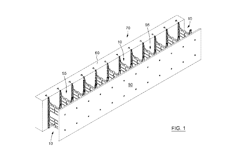
Figure 1 is a perspective view of a wall form assembly provided with a
plurality of
hybrid connectors, according to an optional embodiment of the present
invention;
CA 02904218 2015-09-04
WO 2014/138841
PCT/CA2013/050211
7
Figure 2 is a perspective view of a hybrid connector for tying together a
detachable and a foam panel, according to an optional embodiment of the
present invention;
Figure 3 is another perspective view of the hybrid connector of Figure 2;
Figure 4 is a side view of the hybrid connector of Figure 2;
Figure 5 is a perspective view of a plurality of hybrid connectors being shown
without the foam panel but removably connected to a detachable panel,
according to an optional embodiment of the present invention;
Figure 6 is a perspective view showing mechanical fasteners being used to
removably connect a detachable panel to a plurality of hybrid connectors,
according to an optional embodiment of the present invention;
Figure 7 is a perspective view of a plurality of assemblies being arranged
into a
mold for creating a wall formation, according to an optional embodiment of the
present invention;
Figure 8 is a perspective view of the assemblies of Figure 7, being shown
filled
with a flowable material;
Figure 9 is a perspective view of the filled assemblies of Figure 8, where a
detachable panel is shown removed so as to expose an outer surface of the wall
formation; and
Figures 10A to 10D are enlarged views of the circled area of Figure 9, showing
the insertion of a tool into the recess of at least one screw-receiving sleeve
so as
to break a head of said sleeve, according to an optional embodiment of the
present invention.
CA 02904218 2015-09-04
WO 2014/138841
PCT/CA2013/050211
8
Figure 11 is a perspective view of a foam panel, according to an optional
embodiment of the present invention.
Description of optional embodiments
The present invention can be employed to make a form, or plurality of forms,
for
receiving a pour of a flowable material, such as concrete, cement, or the
like,
into a cavity defined by the form. Once the flowable material sets or hardens
into
a formation, the present invention allows for an outer surface of the
formation to
be exposed, thereby providing an exposed outer surface which can be smooth,
visually appealing, and free from protrusions and abrasions.
According to an aspect of the present invention, there is provided a hybrid
connector 10, examples of which are shown in Figure 1. The hybrid connector
10 is used to tie together a detachable panel 50 and a foam panel 60. The
panels 50,60 can be of any suitable shape and size to create the desired wall
form or formation. The detachable panel 50 can be made of plywood or another
suitable material. The foam panel 60 can be made of polystyrene foam, or any
other suitable insulating material. The foam panel 60 can also take any
suitable
form. For example, and as shown in Figure 11, the foam panel 60 can have an
"undulated" or "ridged" inner surface. In addition, the inner surface of such
a
foam panel 60 can have mounts integrated therein for mounting to the connector
10 or a portion thereof. The foam panel 60 can also have joints mounted on the
top and bottom surfaces of the foam panel 60 for connecting vertically to
other
respective foam panels 60.
The hybrid connector 10 maintains the panels 50,60 in opposed and parallel
spaced relation. The expression "opposed and parallel spaced relation" refers
to
the orientation of the panels 50,60 when connected to the hybrid connector 10.
Such an orientation allows for the panels 50,60 to be distanced or "spaced"
from
each other so as to define a void 55, and further allows the panels to be
aligned
CA 02904218 2015-09-04
WO 2014/138841
PCT/CA2013/050211
9
parallel with each other. Although shown in Figure 1 as being parallel and in
a
horizontal alignment, the panels 50,60 can also have other alignments, such as
vertical, angled, or any combination in between. The hybrid connector 10
maintains the panels 50,60 along a longitudinal direction. The expression
"along
a longitudinal direction" refers to the orientation of the connector 10 when
connected to the panels 50,60. An example of such an orientation is provided
in
Figure 1. As shown, the connector 10 is vertically positioned between both
panels 50,60. It can thus be appreciated that the tying together of the panels
50,60 by the connector 10 creates a form or assembly 70, having a void 55,
which can receive the flowable material. The connectors 10 can be affixed to
adjacent connectors 10 in a vertical orientation, so as to combine multiple
assemblies 70. In addition, the connector 10 can be symmetrical for providing
"reversibility" functionality, meaning that it can be used regardless of which
side
is up or down. Upon setting and hardening, this flowable material will create
the
desired formation, as further explained below.
The connector 10 will now be further described with reference to Figures 2 to
4,
which provide examples of the connector 10 shown in isolation.
The connector 10 has a first elongated side member 20 (or simply "first
member") and an opposed second elongated side member 30 (or simply
"second member"). The term "opposed" when used to describe the relationship
of the first and second members 20,30 refers to their position on distinct, or
"opposite" sides of the connector 10. The first member 20 is typically
embedded
longitudinally within the foam panel 60, and forms an integral part thereof.
Such
integration of the first member 20 can occur during the manufacture or
assembly
of the foam panel 60, during which the first member 20 can be inserted along
an
orientation perpendicular to the length of the foam panel 60 (i.e. a
"vertical"
orientation). The embedding of the first member 20 can allow for the connector
10 to better support the loads generated by the flowable material as it is
poured
into the void 55, or as it settles or hardens.
CA 02904218 2015-09-04
WO 2014/138841
PCT/CA2013/050211
The second member 30 is intended to be removably secured to the detachable
panel 50. As such, the second member 30 can facilitate the removal of the
detachable panel 50 from an exposed outer surface of the formation, as further
explained below. The expression "removably secure" refers to the ability of
the
5 second member 30 to be affixed to the detachable panel 50 during the
creation
of the form, or during the pouring of the flowable material, for example. The
expression also refers to the ability of the second member 30 to be relatively
easily removed from the detachable panel 50 when desired, such as upon the
flowable material hardening, for example.
10 The connector 10 also has a web member 40 which connects longitudinally
(i.e.
in a vertical orientation) the first member 20 with the second member 30. The
web member 40 also helps to support the connector 10 against the loads
produced by the flowable material. As an example, the pouring of the flowable
material into the void 55 formed between the panels 50,60 can place
significant
pressure on the panels 50,60, forcing them to move or separate. In connecting
the panels 50,60 together, the web member 40 thus "anchors" the panels 50,60,
and helps them better resists these loads. It is thus apparent that the web
member 40 is not limited to the shape shown in Figures 2 to 4, and can have a
different shape, size, or configuration depending upon the following non-
exhaustive list of factors: the anticipated loads produced by the flowable
material, the size of the panels 50,60, the cost of materials, etc.
Optionally, the
web member 40 can have one or more retaining members 42 into which can be
inserted and maintained a corresponding reinforcement bar, disposed
horizontally.
Referring to Figure 2, the second member 30 also includes an elongated support
frame 32. The support frame 32 can extend along the entire length of the
second member 30, or only along a portion thereof. The support frame 32
connects with the web member 40, so as to provide a link between the second
member 30 and the first member 20. The support frame 32 can connect to the
CA 02904218 2015-09-04
WO 2014/138841
PCT/CA2013/050211
11
web member 40 using many different techniques. In one possible embodiment,
the support frame 32 can consist of an elongated rod extending the length of
the
second member 30, which can be slid into corresponding grooves protruding
from one side of the web member 40. In another possible embodiment, the
support frame 32 and the web member 40 can interlock with each other, using a
"click"-producing mechanism. In yet another possible embodiment, the support
frame 32 is mounted like a hinge to the web member 40, which can permit the
support frame 32 (and thus the second member 30) to pivot or rotate about the
web member 40. This last configuration may be suitable for transportation and
storage purposes, because it may allow the connector 10 to collapse unto
itself.
The second member 30 further includes at least one screw-receiving sleeve 34
(or simply "sleeve"). The at least one sleeve 34 can be many sleeves 34
distributed throughout the second member 30. Optionally, the plurality of
vertical
sleeves 34 can be aligned vertically with each other. The sleeve 34 allows the
second member 30 to be mounted to the detachable panel 50, and also allows
for the detachable panel 50 to be removed from the second member 30. Each
sleeve 34 can extend transversally from the support frame 32. The expression
"extend transversally" refers to the orientation of the sleeve 34, in that the
sleeve
34 extends substantially perpendicularly from the support frame 32. The sleeve
34 is "screw-receiving", meaning that it can receive a screw or other suitable
mechanical fastener which would permit the sleeve 34 to be secured to the
detachable panel 50, and removed therefrom.
In some optional embodiments, the sleeve 34 has a free end 36 which can abut
against an interior surface of the detachable panel 50 when the second member
30 is secured to thereto. The free end 36 can be located at one end of the
sleeve 34 and away from the support frame 32. It is therefore "free" because
it
corresponds to the end of the sleeve 34 not joined to the support frame 32.
The
free end 36 has an exterior face 41 which may face away from the support
frame 32, and which can be arranged flush with the interior surface of the
CA 02904218 2015-09-04
WO 2014/138841
PCT/CA2013/050211
12
detachable panel 50 when the second member 30 is secured thereto. The
exterior face 41 may include a recess 39 or pit, which can receive a suitable
tool,
or which can serve to hide any fastener inserted into the open passage formed
by a hollow sleeve 34 when the flowable material hardens. The flush
arrangement of the exterior face 41 with the interior surface of the
detachable
panel 50 allows for exterior face 41 to be flush with the exposed outer
surface of
the formation when the detachable panel 50 is removed.
In some optional embodiments, the free end 36 of the sleeve 34 can have
and/or consist of a cylindrical head 38. The cylindrical head 38 can be made
of
any suitable material, or manufactured in such a fashion, that it can be
easily
broken by a worker on site. Optionally, the head 38 can be made of a frangible
material or link such as a hollow thermoplastic. Further optionally, the head
38
can be manufactured to have loose fracture links integrated within it, which
would permit the head 38 to be fractured or broken along those links. The
removal of the broken head 38 leaves a cavity, described in more detail below,
in the exposed outer surface of the formation once the detachable panel 50 is
removed. The cavity advantageously may allow for the mounting of appropriate
fixtures or supports to the exposed outer surface. Alternatively, the cavity
can be
filled in, or the head 38 can be left in place unbroken.
In some optional embodiments, the sleeve 34 has a main portion 35, which
extends from the support frame 32 and links to the cylindrical head 38 by
means
of frangible links. The main portion 35 can take on any suitable configuration
or
shape. Optionally, the main portion 35 is a hollow tube. Such a hollow tube
allows for the formation of an open passage in the exposed outer surface of
the
formation. Indeed, once the flowable material is poured into the void 55, the
hollow tube main portion 35 prevents the flowable material from filling the
volume enclosed by the hollow tube, which results in this volume forming the
open passage when the flowable material sets and hardens.
CA 02904218 2015-09-04
WO 2014/138841
PCT/CA2013/050211
13
In some optional embodiments, the second member 30 includes a reinforcing
structure 31, better shown in Figure 4. The reinforcing structure 31
reinforces
the sleeve 34 against the loads which may be generated by the flowable
material. The reinforcing structure 31 can thus take any suitable form or
configuration to achieve such functionality. In one possible configuration, an
example of which is shown in Figure 4, the reinforcing structure 31 expands
between the free end 36 of each sleeve 34 toward the support frame 32, thereby
forming a shape that is substantially triangular. Such a triangular
reinforcing
structure 31 may better support the load or weight of the flowable material,
and
thus help to keep the panels 50,60 together.
In another possible configuration, the expanded reinforcing structure 31 can
expand until just short of the support frame 32, and form a continuous link
with
the adjacent reinforcing structure 31 via a force link 33, which may help in
distributing and resisting the loads generated by the flowable material.
Optionally, the reinforcing structure 31 can have a retaining member 37 into
which a corresponding horizontal retaining bar (i.e. rebar) can be inserted
and
retained, such as through press-fitting, as but one example. The retention of
such a retaining bar in the retaining member 37 can help the connector 10
better
resist the loads, and also serve to support the formation when the flowable
material sets and hardens.
According to another aspect of the present invention, there is provided a wall
form assembly 70, and example of which is shown in Figure 1. The assembly 70
receives the flowable material and acts as a form in which the flowable
material
can set and harden so as to create the desired formation. The assembly 70 has
a detachable panel 50 and a foam panel 60, as well as a hybrid connector 10,
such as the one described above. Multiple assemblies 70 can be used to create
the formation, as will be discussed further below, and can be stacked one atop
another or side-to-side, depending on the formation to be created.
CA 02904218 2015-09-04
WO 2014/138841
PCT/CA2013/050211
14
According to another aspect of the present invention, there is provided a
method
for creating a desired formation from a flowable material. Examples of the
steps
of the method are provided in Figures 5 to 10D.
The method includes the step of providing a detachable panel 50 and a foam
panel 60. The method further includes the step of tying these panels 50,60
together using a hybrid connector 10 such as the one described above, or
multiple such connectors 10, which creates an assembly 70 into which the
flowable material can be poured. Figure 5 illustrates an optional embodiment
where multiple connectors 10 are removably joined along their respective
second members 30 to an interior surface 52 of the detachable panel 50.
Optionally, the exterior face 41 of the sleeve 34 is mounted flush to the
interior
surface 52 of the detachable panel 50, as previously explained. As shown in
Figure 6, as the exterior face 41 of the sleeve 34 is brought flush with the
interior
surface 52, fasteners 12 (e.g. nails) can be inserted into each main portion
35 so
as to fix the detachable panel 50 to the connector 10. Alternatively, the
detachable panel 50 can be prefabricated with the connectors 10 attached.
Once the panels 50,60 are brought together by the connector 10, the form or
assembly 70 thus made is ready to create the formation.
A plurality of assemblies 70 can be provided so as to create an appropriate
form
for the formation, an example of which is shown in Figure 7. The method
includes the steps of pouring the flowable material into such a form, and
allowing
the flowable material to harden within the form so as to create the formation
90.
An example of multiple assemblies 70 being filled with a flowable material is
shown in Figure 8. Once the formation 90 is suitably set and hardened, the
method includes the step of removing at least one detachable panel 50 from the
formation 90, so as to expose an outer surface 92 of the formation, as
exemplified in Figure 9. The removal of the detachable panel 50 can be
achieved by unscrewing or removing the mechanical fasteners 12 from the
sleeves 34. It can thus be appreciated that the removal of the detachable
panel
CA 02904218 2015-09-04
WO 2014/138841
PCT/CA2013/050211
50 leaves a smooth and protrusion-free exposed outer surface 92, which can
include multiple locations having embedded sleeves 34 and exterior faces 41
which are flush with the exposed outer surface 92.
The heads 38 of these sleeves 34 can thus be left embedded within the exposed
5 outer surface 92, or can be broken and removed therefrom so as to form
cavity,
as exemplified in Figures 10A to 10D. Referring to Figure 10A, the heads 38 of
the sleeves 34 are shown being flush with the exposed outer surface 92. Also
shown are the recesses 39 which can be included in the exterior faces 41 of
the
sleeves 34. The formation of the cavity 14 in the exposed outer surface 92 can
10 be achieved by inserting a tool 16, such as a ratchet, or the operative
end
thereof, into the recess 39, as exemplified in Figures 10B and 100. Once
inserted therein, the tool 16 can be rotated so as to break the head 38. This
can
be achieved, for example, with a recess 39 which is substantially rectangular
in
shape. If the tool 16 has a round or non-rectangular shape, the rotation of
the
15 tool 16 once it is inserted in the recess 39 will cause the frangible
head 38 to
break. Once so broken, the tool 39 can be removed, as well as the broken head
38, leaving only a cavity 14, as exemplified in Figure 10D.
In light of the preceding, it can thus be appreciated that the present
invention
allows for the creation of a wall formation from which an exposed outer
surface
thereof can be quickly and easily revealed, said exposed outer surface
providing
a smooth and protrusion-free surface for being used or displayed as desired.
More particularly, the removable mounting of the sleeve 34, and thus the
second
member 30, to the detachable panel 50 prior to receiving the pour of flowable
material allows for the formation of a substantially smooth outer surface, as
well
as the creation of an interior passage therein.
As can be appreciated from Figure 1, thanks to the specific characteristics of
the
connector 10 according to the present invention, the panels 50,60 once tied
with
CA 02904218 2015-09-04
WO 2014/138841
PCT/CA2013/050211
16
the help of the connectors 10 are easily foldable with respect to one another
and
thus can be shipped to the site of construction in a well compacted form.
Once a form for receiving flowable material is mounted using a plurality of
stacked horizontal rows of form wall assemblies 70, the empty cavity 55
existing
between the form wall made of foam and detachable panels 50,60 can be easily
filled with concrete or with a cement-based material. After hardening of the
flowable material, a composite wall 90 is obtained with the panels 60 firmly
attached through the connectors 10 to the concrete inside-wall, having an
exposed outer surface 92.
Although optional embodiments of the invention have been described in detail
herein and illustrated in the accompanying drawings, it is to be understood
that
the invention is not limited to those precise embodiments and that various
changes and modifications may be effected therein without departing from the
scope of the invention.