Note: Descriptions are shown in the official language in which they were submitted.
CA 02904457 2017-02-15
LED RING ASSEMBLY
This application claims priority based on U.S. Patent Application 14/592,032
entitled "LED RING ASSEMBLY" filed January 8, 2015.
Technical Field of the Invention
The present application relates generally to heat dissipation systems. More
particularly, the present application relates to an LED assembly that
efficiently dissipates
heat from the LED.
Background of the Invention
Light emitting diodes ("LEDs") are energy efficient devices that emit light.
LEDs
are typically more durable and require less power than conventional lighting
technology,
making them ideal for lights that are frequently in use, such as, for example,
street lights.
However, LEDs generally produce heat as a by-product of light production and
such heat
can damage the surrounding structure or LED if it not effectively dissipated.
Currently, LED heat dissipation assemblies include a heat sink with, for
example,
fins that dissipate the heat from the lighting device to the environment. The
heat sink is
typically connected to the LED so heat can be conducted directly or indirectly
from the
LED to the heat sink, and ultimately, away from the lighting device.
Conventional heat dissipation assemblies require direct or near direct
connection
between the heat sink and LED to effectively receive and dissipate the heat.
The heat
sink must also be exposed to the outside atmosphere to disperse the excess
heat away
from the LED device, thus causing concerns of corrosion and the like. These
spatial
1
CA 02904457 2015-09-16
constraints, in addition to the necessary bulk of the heat sink, limit the
locations for other
parts of the LED device and inefficiently dissipate heat.
Summary of the Invention
The present application discloses a lighting device that includes a heat sink
coupled to a heat dissipation structure. The heat dissipation structure can
include an
extension portion with heat conduits that are operatively connected to the LED
to receive
and emit heat from the LED. The heat conduits efficiently conduct heat from
the LED to
the heat sink, which then emits the heat away from the lighting device, so as
to protect
the internal components of the lighting device, while still enabling distal
placement of
the heat sink relative to the LED.
In particular, the present application discloses a lighting device including a
light
emitting structure, a housing adapted to house the light emitting structure, a
reflector
disposed within the housing and adapted to reflect light emitted from the
light emitting
structure, and a heat dissipation structure coupled to the housing and
including a heat
conduit operatively coupled to the light emitting structure to receive heat
therefrom, and
a heat sink distally disposed relative to the light emitting structure and
operatively
coupled to the heat conduit to receive the heat therefrom and to dispense the
heat away
from the light emitting structure.
Also disclosed is a heat dissipation structure including a cap, an extension
portion
extending from the cap, a body extending from the extension portion, a light
emitting
device coupled to the cap, a heat conduit operatively coupled to the light
emitting device
and adapted to transfer heat away from the light emitting device, and a heat
sink distally
disposed relative to the light emitting device and operatively coupled to the
heat conduit
2
CA 02904457 2015-09-16
and adapted to receive heat from the heat conduit and dispense the heat away
from the
heat dissipation structure.
Brief Description of the Drawings
For the purpose of facilitating an understanding of the subject matter sought
to be
protected, there are illustrated in the accompanying drawings embodiments
thereof, from
an inspection of which, when considered in connection with the following
description,
the subject matter sought to be protected, its construction and operation, and
many of its
advantages should be readily understood and appreciated.
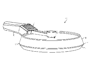
FIG. 1 is a perspective view of a lighting device according to an embodiment
of
the present application.
FIG. 2 is an exploded perspective view of a lighting device according to an
embodiment of the present application.
FIG. 3 is an exploded perspective view of a heat dissipation structure
according
to an embodiment of the present application.
FIG. 4 is an assembled perspective view of a heat dissipation structure
according
to an embodiment of the present application.
Detailed Description of the Embodiments
While this invention is susceptible of embodiments in many different forms,
there
is shown in the drawings, and will herein be described in detail, a preferred
embodiment
of the invention with the understanding that the present disclosure is to be
considered as
an exemplification of the principles of the invention and is not intended to
limit the broad
aspect of the invention to embodiments illustrated.
The present application discloses a lighting device that includes a heat sink
operatively connected to and distally disposed relative to an LED. The heat
generated
3
CA 02904457 2015-09-16
through operation of the LED is transferred to the heat sink through one or
more heat
conduits to allow greater spatial variability of the lighting device and
protect the internal
components of the lighting device.
As shown in FIG. 1, a lighting device 100 is shown and can include an upper
housing 105, a lower housing 110, and an upper gasket 115 and a lower gasket
120
sandwiched between the upper housing 105 and the lower housing 110. The
lighting
device 100 can also include a heat dissipation structure 125 that receives
heat from the
lighting device 100 and emits it away from the lighting device 100 via the
heat sink 130.
FIG. 2 is an exploded view of the lighting device 100 according to an
embodiment of the present application. As shown, the lighting device 100 can
include a
lens 135 disposed between the upper gasket 115 and the lower gasket 120 and
adapted to
direct or magnify light emitted from the lighting device 100. Also shown is a
reflector
140 that can reflect light from the back side of the lighting device 100
through the lens
135 and into the desired illumination area. A bracket 145 can be disposed
within the
upper housing 105 and can act as a structural backbone of the lighting device
100. For
example, the bracket 145 can include a coupling member 150 disposed near a
center of
the upper housing 105 and adapted to anchor the assembly of the lighting
device 100
against the upper housing 105. For example, as shown, the coupling member 150
is
coupled to a standoff 155, which in turn is coupled to a fastener 160 and a
washer 165.
Together, the standoff 155, fastener 160 and washer 165 can couple the lower
housing
110, lower gasket 120, lens 135, upper gasket 115, and reflector 140 to the
upper housing
105 through the coupling member 150.
A driver 170 can also be included in the upper housing 105 to control
operation
of the lighting device 100. For example, the driver 170 can control the times
at which the
4
CA 02904457 2015-09-16
lighting device 100 is illuminated, and the frequency or intensity at which
the lighting
device is illuminated. The driver 170 can also control output of power to
lighting
structures such as LEDs so as not to under-power or over-power the LEDs and
cause a
malfunction.
The heat dissipation structure 125 will now be discussed with reference to
FIGS
2-4. As shown in FIG. 2, the heat dissipation structure 125 can include a heat
sink 130
distally disposed relative to the light emitting structure 200 and adapted to
dispense heat
away from the light emitting structure 200 to the environment. The heat
dissipation
structure 125 can include a cap 175, an extension portion 180 extending from
the cap
175, and a body 185 extending from the extension portion 180. The body 185 can
optionally include an opening 190 adapted to receive the heat sink 130.
Further, a plate
195 can enclose the body 185 or any other component of the heat dissipation
structure
125. The light emitting structure 200 can be coupled to the heat dissipation
structure 125
so heat can be dissipated from the light emitting structure 200 towards the
heat sink 130
and ultimately away from the lighting device 100. For example, the heat
dissipation
structure 125 can include one or more heat conduits 205 having a linear
portion 205a
located proximate the light emitting structure 200 and adapted to dispense
heat away
from the light emitting structure 200, and towards an angled portion 205b
extending
from the linear portion 205a at an angle and located near the heat sink 130.
The heat
conduits 205 can be disposed within one or more groups 210 that can extend
from the
cap 175 through the extension portion 180 and to the body 185. A cover 215 can
enclose
the heat conduits 205 within the heat dissipation structure 125.
The upper housing 105 and lower housing 110 can be any structure that allows
for a clamshell-type housing configuration. As shown, the upper housing 105 is
circular
5
CA 02904457 2015-09-16
shaped with an enclosed top portion, but any shape or size of the upper
housing 105 can
be implemented without department from the spirit and scope of the present
invention.
Similarly, the lower housing 110 is also circular in shape and defines an
opening for the
lens 135, so as to allow light to be emitted from the light emitting structure
200 and into
the desired lighting area.
The upper gasket 115 and lower gasket 120 can be any composition and any
shape to allow for a mechanical seal between the necessary components. For
example,
the upper gasket 115 can provide a seal between the reflector 140 and the lens
135.
Similarly, the lower gasket 120 can provide a seal between the lens 135 and
lower
housing 110. The upper 115 and lower 120 gaskets can be made of any material,
for
example, silicon or rubber, and need not create an air-tight or liquid-tight
seal.
The lens 135 allows light to be emitted away from the lighting device 100 and
onto the illumination area. The lens 135 can be transparent and/or colored so
long as
light is allowed to pass through in some manner. The lens 135 can be made of
any
material, and in a preferred embodiment is made of clear acrylic.
The heat sink 130 can be any structure that dispenses heat away from the light
emitting structure 200 to the environment. As shown, the heat sink 130
includes fins to
increase the surface area of the heat sink 130 and allow more heat to
dissipate from the
lighting device 100. However, any structure or any material can be implemented
as the
heat sink 130 so long as the structure dispenses heat away from the lighting
device 100.
The light emitting structure 200 can be any object or device that emits light.
For
example, the light emitting structure can be an LED, light bulb, fluorescent
bulb, liquid
crystal display (LCD), plasma screen, or any other device capable of emitting
light. In a
preferred embodiment, the light emitting structure 200 is an LED.
6
CA 02904457 2015-09-16
The heat conduit 205 can be made of any material and can be any structure that
allows for the transfer of heat from the light emitting structure 200 towards
the heat sink
130. As shown, the heat conduit 205 includes a linear portion 205a located
proximate the
cap 175, and accordingly, proximate the heat emitting structure 200, so as to
receive the
heat from the heat emitting structure 200. The heat conduit 205 can also
include an
angled portion 205b extending from the linear portion 205a and located
proximate the
heat sink 130. In this manner, the heat conduit 205 can transmit heat from the
light
emitting structure 200 towards the heat sink 130, and due to the greater
surface area
contact between the angled portion 205b and the heat sink 130, can transmit
more of the
heat away from the light emitting structure 200 and ultimately away from the
lighting
device 100. The heat conduit 205 can be tubular in nature, i.e., can be hollow
inside, to
allow for even greater surface area to dissipate heat. Also, the heat conduit
205 can
include multiple heat conduits, and is not limited to a singular heat conduit
205.
The light emitting structure 200 can be coupled to the heat dissipation
structure
125 at the cap 175, as shown. In this manner, the heat dissipation structure
125 can
transfer the heat from the light emitting structure 200 towards an area of the
lighting
device 100 where spatial constraints are not as prevalent. This arrangement
allows for the
heat sink 130 to be disposed in a variety of different areas on the lighting
device 100,
therefore allowing greater variability in engineering the lighting device 100.
As discussed herein, the term "coupled" is intended to refer to any
connection,
direct or indirect, and is not limited to a direct connection between two or
more elements
of the disclosed invention. Similarly, "operatively coupled" is not intended
to mean any
direct connection, physical or otherwise, and is merely intended to define an
arrangement
7
CA 02904457 2015-09-16
where two or more elements communicate through some operative means (e.g.,
through
conductive or convective heat transfer, or otherwise).
The matter set forth in the foregoing description and accompanying drawings is
offered by way of illustration only and not as a limitation. While particular
embodiments
have been shown and described, it will be apparent to those skilled in the art
that changes
and modifications may be made without departing from the broader aspects of
Applicant's contribution. The actual scope of the protection sought is
intended to be
defined in the following claims when viewed in their proper perspective based
on the
prior art.
8