Note: Descriptions are shown in the official language in which they were submitted.
CA 02904576 2016-10-24
85362-20
CONTAINER END CLOSURE WITH BUCKLE CONTROL FEATURE
FIELD OF THE INVENTION
Embodiments of the present invention generally relate to containers and
container end closures,
and more specifically metallic beverage container end closures with buckle
control features.
BACKGROUND OF THE INVENTION
Containers, and more specifically metallic beverage containers, generally
contain a neck on an
upper portion that is adapted for interconnection to a metallic end closure.
The container end closure is
formed from a flat sheet of metallic material and generally includes a pull
tab or other form of stay on tab
("SOT"). Beverage containers commonly store carbonated beverages, thus, both
the container body and
the container end closure are required to withhold internal pressures up to 90
psi while under varying
temperatures without catastrophic failure or permanent deformation. Further,
the container end closure
must be manufactured, stacked, shipped, and sent to a filler prior to being
seamed onto a container body
filled with a carbonated beverage. Thus, the container and end closure must be
designed to resist
deformation and failure while utilizing thin metallic materials and allowing
compact stacking during
shipping and manufacturing.
Food and beverage containers with pull tabs or SOTs are generally known.
Various SOTs and
related features are disclosed, by way of example, in U.S. Patent 7,926,675 to
Rieck et al. Known end
closures, however, generally may buckle when under varying temperatures and
internal pressure. If an
end closure buckles near the score lines, tear panel, or pour opening, the
score line may fail and release
the pressurized contents of the container. Many users of conventional devices,
such as SOTs for
pressurized containers, may have experienced "peak and leak" when they have
left pressurized containers
in their cars under hot conditions. As the heat of the car increases, so does
the internal temperature and
internal pressure of the container. The increased internal pressure causes the
end closure to buckle and
crack the score, thus spilling the contents of the container. Peak and leak is
when the end closure
buckles and causes the score line to fracture such that the contents of the
container leak out. Peak and
leak may result in not only the failure of a specific can, but the spoilage of
other containers once they
become covered with carbonated soda or beer. Accordingly, there exists a
significant need for a beverage
container end closure that will not buckle near the score line or tear panel
such that the score line cracks
causing catastrophic failure.
1
CA 02904576 2016-10-24
85362-20
Previous attempts have been made to manufacture container end closures that
resist buckling
near the opening, or control where the buckling occurs. Prior art methods of
reducing burst-before-
buckle used a coined bead at the 6 o'clock position to reduce flexure or
modified the deboss wall in front
of the 6 o'clock score position to eliminate deboss buckle. Note that "induced
buckle coin" may be used
interchangeably herein with "buckle coin."
For purposes of further disclosure, the following references generally related
to end panels with
buckle control features :
Japanese Patent Publication No. JP2002145263 to Yoshihiko;
Japanese Patent Publication No. JP2000159229 to Yoshihiko;
U.S. Patent No. 5,829,623 issued to Otsuka et al. on Nov. 3, 1998; and
U.S. Patent No. 8,157,119 issued to Watson et al. on April 17, 2012.
Due to the numerous limitations associated with the prior art described above,
the following
disclosure describes an improved container end closure that is adapted for
interconnection to a container
body and that employs buckle control features. This novel feature may provide
control of the buckle
location, may significantly improve the end closure's buckle resistance near
the opening and score line,
and may reduce the likelihood of catastrophic failure along with the release
of carbonated beverages.
SUMMARY OF THE INVENTION
These and other needs may be addressed by the various embodiments and
configurations of the
present invention. This disclosure relates to a novel system, device, and
method for providing a food and
beverage container end closure with controlled buckle located away from the
tear panel and score line.
The novel end closure provided herein buckles on the central panel portion in
a predetermined location
opposite the tear panel so that buckling does not occur near the score line or
opening, and cause
premature opening or "peak and leak."
During pressurization of a standard end closure, one can visually see the
flexing of the panel and
score at the 6 o'clock position regardless of the manufacturing process. The
2
CA 02904576 2015-09-08
WO 2014/149485 PCT/US2014/018866
6 o'clock position of the end closure is between the score line and the
countersink at a
point along the end closure's vertical center line opposite the tab lift tail
or pull ring, and
positioned proximate to the pour opening. Thus, if an analog clock face was
placed on the
end closure, the 6 o'clock position of the end closure would be where the
number six is
located on the clock face. The close proximity of the deboss and score to the
peripheral
edge of the central panel creates the weakest area on the panel face. When an
end closure
with a large, wide score profile is under pressurization, the score path bows
at the 6
o'clock position and can subsequently fracture the score and cause failure and
leakage. By
using an induced buckle coin in an upper quadrant of the end closure (i.e., a
quadrant
without a score line), the upper quadrant becomes the weakest area on the
panel face, thus
shifting the bowing away from the 6 o'clock score position, allowing buckling
in a
predetermined location opposite the score, and preventing catastrophic
failure.
Features of the present disclosure may be employed in a wide range of food and
beverage containers, including pressurized beverage containers with SOTs
secured by a
rivet, food containers with tear away lids, and full-panel easy-open end tabs,
to name a
few. Although the invention generally relates to metallic end closures and
containers, the
invention and features described herein could easily be implemented on various
types of
plastic containers and plastic end closures. Additionally, the present
invention is generally
shown and described with a metallic beverage container end closure; however,
the present
invention may be employed with an end closure of any size, shape, material,
and
geometry.
It is thus one aspect of various embodiments of the present invention to
provide an
inexpensive metallic end closure with improved buckle resistance to avoid
buckling near
the score line or tear panel and to avoid catastrophic failure, which allows
premature
opening and spillage.
It is another aspect of various embodiments of the present invention to
provide a
conventional end closure with buckle control features to isolate where
buckling occurs
when the container pressure is raised above a predetermined level. One
advantage of some
embodiments is that the end closure buckling is controlled to certain
locations on the end
closure, such locations may be away from the score lines and opening.
Another aspect of embodiments of the present invention is to provide a method
for
manufacturing an end closure with buckle control features. More specifically,
a method
for forming a beverage can end closure is provided, wherein the container end
closure is
provided with a buckle coin on the panel of the end closure proximate the pull
ring or tab
3
CA 02904576 2016-10-24
85362-20
tail (i.e., on the portion of the panel opposite the opening). In some
embodiments, the end closure
may also have an interrupted panel coin.
It is one aspect of embodiments of the present invention to provide a
container end closure
with buckle control features that is manufactured using conventional
manufacturing equipment. In
some embodiments, the buckle coin is formed with well known end closure
manufacturing tools
and dies including forms, coining (e.g., thinning), or a combination of forms
and coining.
In various embodiments, an end closure is provided with a SOT, a buckle coin
in the
panel, and an interrupted panel coin around the peripheral edge of the panel.
In some
embodiments, the buckle coin may be disposed generally proximal to the panel
edge and in a
quadrant of the panel comprising at least a portion of the pull ring or tab
tail. In one embodiment,
the interrupted panel coin may have only one interruption. In alternative
embodiments the
interrupted panel coin may have two or more interruptions. In various
embodiments, the one or
more interruptions may be positioned proximate an induced buckle coin. Note
that "peripheral
edge" may be used interchangeably herein with "panel edge," "panel radius,"
and "panel
circumference."
In one embodiment of the present invention, a metallic end closure comprises
an induced
buckle coin and an interrupted panel coin. In another embodiment the end
closure comprises an
induced buckle coin, an interrupted panel coin, and a continuous panel coin.
The continuous panel
coin may be an annular band of reduced thickness (referred to in the industry
as "coining") along
3600 of the shoulder of the central panel to provide additional resistance to
buckling, as is known
in the art. See, e.g., U.S. Patent No. 5,590,807 to Forrest; U.S. Patent Nos.
4,796,772 and
4,577,774 to Nguyen; and U.S. Patent No. 5,829,623 to Otsuka.
In one embodiment, a container end closure adapted for interconnection to a
container
body is provided. The end closure comprises: a peripheral curl, a chuck wall,
a countersink having
an outer panel wall and an inner panel wall, a central panel, a pull tab, a
buckle coin positioned in
a quadrant of the end closure without the score, and an interrupted panel
coin. Note that the pull
tab lift ring is positioned on a tail end of the pull tab, opposite the nose
end of the tab.
Additionally, in some embodiments, the pull tab may be a promotional tab and
not comprise a ring
or aperture at all. Rather, the pull tab lift tail may be substantially solid
and comprise a
promotional saying, name, mascot, shape, or symbol. Thus, the terms "lift
ring," "pull ring," "lift
tail," and "tail" may be used interchangeably herein. The "pull tab" may also
be called the "tab".
4
CA 02904576 2015-09-08
WO 2014/149485 PCT/US2014/018866
In one embodiment, a metallic end closure for a beverage container with buckle
control features is provided. The metallic end closure comprises: a peripheral
curl which is
adapted for interconnection to a neck of a beverage container; a chuck wall
extending
downwardly from the peripheral curl; a countersink interconnected to a lower
end of the
chuck wall; an inner panel wall extending upwardly from an interior portion of
the
countersink; a central panel interconnected to an upper portion of the inner
panel wall; a
pull tab having a nose end and a tail end which is operably interconnected to
the central
panel; a first score line in the central panel which defines a tear panel; at
least one induced
buckle coin positioned proximate to a an outer peripheral edge of the central
panel, the
induced buckle coin extending around the central panel no greater than about
45 degrees
as measured from a center point of the end closure; and a non-continuous panel
coin
positioned proximate to a panel radius defined by the upper portion of the
inner panel wall
and the outer peripheral edge of the central panel and interrupted proximate
to the at least
one induced buckle coin, wherein any buckling of the metallic end closure is
initiated
proximate to the induced buckle coin when a pressure within the beverage
container is
elevated above a predetermined level. As appreciated by one skilled in the
art, the features
of embodiments of the presentment invention could be implemented on any
metallic end
closure with a variety of geometries and dimensions.
In some embodiments, a metallic end closure for a beverage container with
controlled buckling characteristics is provided. The metallic end closure
comprises: a
peripheral curl which is adapted for interconnection to a neck of a beverage
container; a
chuck wall extending downwardly from the peripheral curl; a countersink
interconnected
to a lower end of the chuck wall; an inner panel wall extending upwardly from
an interior
portion of the countersink; a central panel interconnected to an upper portion
of the inner
panel wall, the central panel having a substantially planar surface oriented
in substantially
horizontal plane; a pull tab having a nose end and a tail end, the pull tab is
operably
interconnected to the central panel; a first score line in the central panel,
which defines a
substantially hinged tear panel and pour opening; at least one induced buckle
coin
positioned proximate to a first radius defined by the upper portion of the
inner panel wall
and an outer peripheral edge of the central panel, the induced buckle coin
extending
around the first radius no greater than about 90 degrees as measured from a
center point of
the end closure; and a non-continuous panel coin positioned proximate to the
outer
peripheral edge of the central panel and interrupted proximate to the at least
one induced
buckle coin, wherein any buckling of the metallic end closure is initiated
proximate to the
5
CA 02904576 2015-09-08
WO 2014/149485 PCT/US2014/018866
induced buckle coin when pressure within the beverage container is elevated
above a
predetermined level. In one embodiment, the inner panel wall further comprises
a primary
coined region which extends continuously around the first radius.
In various embodiments, a metallic end closure with controlled buckling
characteristics is provided. The metallic end closure comprises: a peripheral
curl which is
adapted for interconnection to a neck of a beverage container; a chuck wall
extending
downwardly from the peripheral curl; a countersink with a first countersink
radius of
curvature interconnected to a lower end of said chuck wall; an inner panel
wall extending
upwardly from an interior portion of said countersink; a central panel with an
outer
peripheral edge interconnected to an upper portion of the inner panel wall at
a panel
radius, the central panel having a substantially planar surface oriented in a
substantially
horizontal plane; a first score line in the central panel, which defines a
substantially hinged
tear panel and pour opening; at least one induced buckle coin positioned
proximate to the
outer peripheral edge of the central panel, the at least one induced buckle
coin having a
width greater than 0.05 inches, and the at least one induced buckle coin
extending
upwardly from the central panel; and a non-continuous panel coin positioned
proximate to
the panel radius and interrupted proximate to the at least one induced buckle
coin, the non-
continuous panel coin having an upper inclined surface positioned at a second
angle
relative to the substantially horizontal plane of the central panel, wherein
any buckling of
the metallic end closure is initiated proximate to the induced buckle coin
when a pressure
within the beverage container is elevated above a predetermined level. In one
embodiment, the metallic end closure further comprises an inner panel wall
with a
continuous panel coin which extends continuously around the panel radius, the
continuous
panel coin having an upper surface positioned at a first angle relative to the
substantially
horizontal plane of the central panel, wherein the second angle is greater
than the first
angle.
Various methods of forming an end closure with a buckle coin and/or an
interrupted panel coin are provided. In one embodiment, a method is provided
comprising
the steps of: providing a blank end panel, forming a rivet at a substantially
central location
on the end panel, coining the end panel, providing one or more scores for an
opening area,
providing a debossed panel, providing a buckle coin, providing an interrupted
panel coin,
and securing a pull tab.
Devices and various methods of the present invention contemplate forming a
buckle coin and a panel coin on an end panel (i.e., central panel of an end
closure) at
6
CA 02904576 2016-10-24
85362-20
various stages of panel formation. For example, a buckle coin and an
interrupted panel coin may be
formed on an end panel before, during, or after formation of features such as
debossed features, rivets,
frangible score lines defining opening areas, etc. In one embodiment, a
forming tool is provided to
form a buckle coin and an interrupted panel coin, while recessed portions of
the tool accommodate
various preformed features of the panel.
In some embodiments, a method of manufacturing an end closure with controlled
buckling
characteristics is provided. The method comprises: providing an end closure
comprising: a
countersink; an inner panel wall extending upwardly from an interior portion
of the countersink; a
central panel interconnected to an upper portion of the inner panel wall, the
central panel having a
substantially planar surface oriented in substantially horizontal plane; a
pull tab having a nose end and
a tail end, the pull tab is operably interconnected to the central panel; and
a first score line in the
central panel, which defines a substantially hinged tear panel; forming at
least one induced buckle coin
in the central panel, the at least one induced buckle coin positioned
proximate to a panel radius defined
by the upper portion of the inner panel wall and an outer peripheral edge of
the central panel; and
forming a non-continuous panel coin proximate to the panel radius, the non-
continuous panel coin
interrupted proximate to the at least one induced buckle coin, wherein any
buckling of the metallic end
closure is initiated proximate to the induced buckle coin when pressure within
the beverage container
is elevated above a predetermined level. In one embodiment, the method further
comprises forming a
continuous panel coin which extends continuously around the first radius.
In accordance with one aspect, a metallic end closure with controlled buckling
characteristics
is provided. The metallic end closure comprises:
a peripheral curl which is adapted for interconnection to a neck of a beverage
container;
a chuck wall extending downwardly from said peripheral curl;
a countersink interconnected to a lower end of said chuck wall;
an inner panel wall extending upwardly from an interior portion of said
countersink;
a central panel interconnected to an upper portion of said inner panel wall,
said central panel
having a substantially planar surface oriented in a substantially horizontal
plane;
a pull tab having a nose end and a tail end, said pull tab operably
interconnected to said central
panel;
a first score line in said central panel, which defines a substantially hinged
tear panel and pour
opening;
7
CA 02904576 2016-10-24
85362-20
at least one induced buckle coin positioned on said central panel and
proximate to an outer
peripheral edge of said central panel, said at least one induced buckle coin
extending around said
central panel no greater than about 90 degrees as measured from a center point
of said end closure;
a panel radius defined by said upper portion of said inner panel wall and said
outer peripheral
edge of said central panel, said panel radius having a first radius of
curvature, and wherein said panel
radius comprises a continuous panel coin which extends continuously around
said panel radius; and
a non-continuous panel coin positioned proximate to said panel radius and
interrupted
proximate to said at least one induced buckle coin, wherein a furthermost
point of said at least one
induced buckle coin from said center point does not extend beyond an innermost
edge of said non-
continuous panel coin, and wherein any buckling of said metallic end closure
is initiated proximate to
said at least one induced buckle coin when a pressure within said beverage
container is elevated above
a predetermined level.
In accordance with another aspect, a method of manufacturing an end closure
with
controlled buckling characteristics is provided. The method comprises:
- providing an end closure comprising:
a peripheral curl;
a chuck wall extending downwardly from said peripheral curl;
a countersink interconnected to a lower end of said chuck wall;
an inner panel wall extending upwardly from an interior portion of said
countersink;
a central panel interconnected to an upper portion of said inner panel wall,
said central
panel having a substantially planar surface oriented in substantially
horizontal plane;
a pull tab having a nose end and a tail end, said pull tab is operably
interconnected to
said central panel; and
a first score line in said central panel, which defines a substantially hinged
tear panel;
- forming at least one induced buckle coin in said central panel,
said at least one induced
buckle coin positioned proximate to a panel radius defined by said upper
portion of said
inner panel wall and an outer peripheral edge of said central panel;
- forming a continuous panel coin which extends continuously around
said panel radius; and
forming a non-continuous panel coin proximate to said panel radius, said non-
continuous
panel coin interrupted proximate to said at least one induced buckle coin,
wherein a furthermost point
of said at least one induced buckle coin from said center point does not
extend beyond an innermost
7a
CA 02904576 2016-10-24
85362-20
edge of said non-continuous panel coin, and wherein any buckling of said
metallic end closure is
initiated proximate to said at least one induced buckle coin when pressure
within said beverage
container is elevated above a predetermined level.
In accordance with another aspect, a metallic end closure with controlled
buckling
characteristics is provided. The metallic end closure comprises:
a peripheral curl which is adapted for interconnection to a neck of a beverage
container;
a chuck wall extending downwardly from said peripheral curl;
a countersink with a first countersink radius of curvature interconnected to a
lower end of said
chuck wall;
an inner panel wall extending upwardly from an interior portion of said
countersink;
a central panel with an outer peripheral edge interconnected to an upper
portion of said inner
panel wall at a panel radius, said central panel having a substantially planar
surface oriented in a
substantially horizontal plane;
a first score line in said central panel, which defines a substantially hinged
tear panel and pour
opening;
at least one induced buckle coin positioned proximate to said outer peripheral
edge of said
central panel, said at least one induced buckle coin having a width greater
than 0.05 inches, and said at
least one induced buckle coin extending upwardly from said central panel;
a non-continuous panel coin positioned proximate to said panel radius and
interrupted
proximate to said at least one induced buckle coin, said non-continuous panel
coin having an upper
inclined surface positioned at a second angle relative to said substantially
horizontal plane of said
central panel; and
a continuous panel coin region which extends continuously around said panel
radius, wherein
any buckling of said metallic end closure is initiated proximate to said at
least one induced buckle coin
when a pressure within said beverage container is elevated above a
predetermined level.
"Coins" and "coining" refer to a metalworking process well known in the art.
Coining may
involve shaping metal by squeezing the metal between two dies to create
thinning. The sheet metal
may have different shapes or designs on each side, thus creating differences
in the thickness of the
metal. Coining may be used to harden and/or shape the metal.
The phrases "at least one," "one or more," and "and/or", as used herein, are
open-ended
expressions that are both conjunctive and disjunctive in operation. For
example, each of the
expressions "at least one of A, B and C", "at least one of A, B, or C", "one
or more of A, B, and C",
7b
CA 02904576 2016-10-24
85362-20
"one or more of A, B, or C" and "A, B, and/or C" means A alone, B alone, C
alone, A and B together,
A and C together, B and C together, or A, B and C together.
7c
CA 02904576 2015-09-08
WO 2014/149485 PCT/US2014/018866
Unless otherwise indicated, all numbers expressing quantities, dimensions,
conditions, and so forth used in the specification and claims are to be
understood as being
modified in all instances by the term "about".
The term "a" or "an" entity, as used herein, refers to one or more of that
entity. As
such, the terms "a" (or "an"), "one or more" and "at least one" can be used
interchangeably
herein.
The use of "including," "comprising," or "having" and variations thereof
herein is
meant to encompass the items listed thereafter and equivalents thereof as well
as
additional items. Accordingly, the terms "including," "comprising," or
"having" and
variations thereof can be used interchangeably herein.
It shall be understood that the term "means" as used herein shall be given its
broadest possible interpretation in accordance with 35 U.S.C., Section 112(f).
Accordingly, a claim incorporating the term "means" shall cover all
structures, materials,
or acts set forth herein, and all of the equivalents thereof. Further, the
structures,
materials, or acts and the equivalents thereof shall include all those
described in the
summary of the invention, brief description of the drawings, detailed
description, abstract,
and claims themselves.
The Summary of the Invention is neither intended nor should it be construed as
being representative of the full extent and scope of the present invention.
Moreover,
references made herein to "the present invention" or aspects thereof should be
understood
to mean certain embodiments of the present invention and should not
necessarily be
construed as limiting all embodiments to a particular description. The present
invention is
set forth in various levels of detail in the Summary of the Invention as well
as in the
attached drawings and the Detailed Description and no limitation as to the
scope of the
present invention is intended by either the inclusion or non-inclusion of
elements,
components, etc. in this Summary of the Invention. Additional aspects of the
present
invention will become more readily apparent from the Detailed Description,
particularly
when taken together with the drawings.
These and other advantages will be apparent from the disclosure of the
invention(s)
contained herein. The above-described embodiments, objectives, and
configurations are
neither complete nor exhaustive. As will be appreciated, other embodiments of
the
invention are possible using, alone or in combination, one or more of the
features set forth
above or described in detail below.
8
CA 02904576 2015-09-08
WO 2014/149485 PCT/US2014/018866
BRIEF DESCRIPTION OF THE DRAWINGS
Those of skill in the art will recognize that the following description is
merely
illustrative of the principles of the present invention, which may be applied
in various
ways to provide many different alternative embodiments. This description is
made for
illustrating the general principles of the teachings of this invention and is
not meant to
limit the inventive concepts disclosed herein.
The accompanying drawings, which are incorporated in and constitute a part of
the
specification, illustrate embodiments of the invention and together with the
general
description of the invention given above and the detailed description of the
drawings given
below, serve to explain the principles of the invention.
Fig. 1 is a top plan view of an embodiment of an end closure with an induced
buckle coin;
Fig. 2 is a cross-sectional perspective view of the end closure of Fig. 1;
Fig. 3 is a cross-sectional view of the end closure of Fig. 1;
Fig. 4 is a top plan view of an embodiment of an end closure with induced
buckle
features;
Fig. 5 is a cross-sectional perspective view of the end closure of Fig. 4;
Fig. 6 is a cross-sectional view of the end closure of Fig. 4;
Fig. 7 is a top plan view of an embodiment of an end closure with induced
buckle
features;
Fig. 8 is an enlarged top plan view of the induced buckle coin of Fig. 7;
Fig. 9 is a cross-sectional view of the end closure of Fig. 7;
Fig. 10 is a cross-sectional view of the end closure of Fig. 7;
Fig. 11 is a cross-sectional perspective view of the end closure of Fig. 7;
Fig. 12 is a top plan view of an embodiment of an end closure with induced
buckle
features;
Fig. 13 is an enlarged top plan view of the induced buckle coin of Fig. 12;
Fig. 14 is a cross-sectional view of the end closure of Fig. 12;
Fig. 15 is a cross-sectional view of the end closure of Fig. 12;
Fig. 16 is a cross-sectional perspective view of the end closure of Fig. 12;
Fig. 17 shows quadrant zones and clock references consistent with embodiments
of
the present invention;
Fig. 18 is a top plan view of an embodiment of an end closure with induced
buckle
features;
9
CA 02904576 2015-09-08
WO 2014/149485 PCT/US2014/018866
Fig. 19 is a top plan view of an embodiment of an end closure with induced
buckle
features; and
Fig. 20 is an enlarged top plan view of an embodiment of an end closure with
induced buckle features.
To assist in the understanding of the embodiments of the present invention the
following list of components and associated numbering found in the drawings is
provided
herein:
No. Component
2 End Closure
4 Central Panel
6 Induced Buckle Coin
8 Panel Radius
10 Interrupted Panel Coin
11 Continuous Panel Coin (360 )
12 Tab
14 Tab Tail
16 Tab Nose
18 Lift Ring
24 Peripheral Curl
26 Chuck Wall
28 Countersink
Countersink Outer Panel Wall
32 Countersink Inner Panel Wall
34 Rivet (may be a centerline rivet)
25 36 Deboss Area
Score Line
42 Pour Opening
R1 Radius of Curvature of Countersink
R8 Radius of Curvature of Panel Radius
30 W1 Width of Panel Wall
H1 Height Countersink to Buckle Coin
H2 Height Countersink to Panel
Al Angle of Continuous Panel Coin
A2 Angle of Interrupted Panel Coin
CA 02904576 2015-09-08
WO 2014/149485 PCT/US2014/018866
It should be understood that the drawings are not necessarily to scale, and
various
dimensions may be altered. In certain instances, details that are not
necessary for an
understanding of the invention or that render other details difficult to
perceive may have
been omitted. It should be understood, of course, that the invention is not
necessarily
limited to the particular embodiments illustrated herein.
DETAILED DESCRIPTION
Although the following text sets forth a detailed description of numerous
different
embodiments, it should be understood that the legal scope of the description
is defined by
the words of the claims set forth at the end of this disclosure. The detailed
description is to
be construed as exemplary only and does not describe every possible embodiment
since
describing every possible embodiment would be impractical, if not impossible.
Numerous
alternative embodiments could be implemented, using either current technology
or
technology developed after the filing date of this patent, which would still
fall within the
scope of the claims.
Referring now to Figs. 1-20, a beverage container end closure and methods and
devices for forming the same according to various embodiments of the present
invention
are shown. Note that the end closures shown in the figures are end closures
before they
are double seamed onto a neck of a container body.
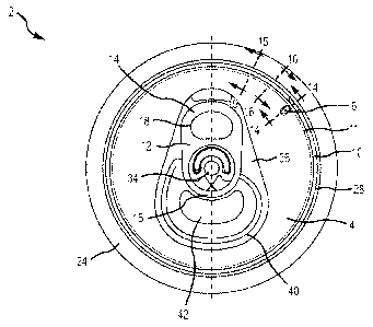
Fig. 1 shows the public side of an end closure 2 after an induced buckle coin
6 has
been manufactured in quadrant I (upper right quadrant) of the end closure 2.
As shown in
Fig. 1, the end closure 2 is divided into four quadrants (I-IV) for the ease
of discussion.
The end closure 2 may comprise a central panel 4, a panel radius 8, a tab 12,
and a
countersink 28 interconnected to a chuck wall interconnected to a peripheral
curl 24. The
tab 12 may comprise a tab nose 16 opposite a tab tail 14 and a lift ring 18.
The tab 12 may
be interconnected to the central panel 4 using a rivet 34. The central panel 4
may
comprise a deboss area 36 and a score line 40 defining a tear panel or pour
opening 42.
The induced buckle coin 6 creates an area of weakness in the end closure 2.
Accordingly, in one embodiment, the induced buckle coin 6 is positioned on the
central
panel 4 in a location proximate to the tail 14 of the pull tab 12 and away
from the score
line 40 such that buckling is induced near the induced buckle coin 6 and away
from the
tear panel 42. The induced buckle coin 6 may be positioned within quadrant I
or quadrant
IV or any quadrant not comprising the score line 40.
In some embodiments, the induced buckle coin 6 may have an oval, a circular, a
triangular, rectangular, a square, a trapezoidal shape, or a promotional shape
such as a
11
CA 02904576 2015-09-08
WO 2014/149485 PCT/US2014/018866
football, baseball, bat, etc. Thus, the induced buckle coin 6 may be any
geometric shape
which can be manufactured into the end closure 2. In one embodiment, the
length of the
induced buckle coin 6 may be measured from the point on the induced buckle
coin 6
farthest away from a center point of the end closure 2 to the point on the
induced buckle
coin 6 closest to the center point of the end closure 2. In some embodiments,
the length of
the induced buckle coin 6 may be between approximately 0.094 inches and 0.096
inches.
The width of the induced buckle coin 6 may be measured from one substantially
linear
side of the induced buckle coin 6 to the other substantially linear side (if
the induced
buckle coin 6 has a substantially linear side). In some embodiments, the width
of the
induced buckle coin may be between approximately 0.054 inches and 0.056
inches. In
other embodiments, the induced buckle coin 6 may be positioned in any position
or any
direction within a quadrant of the end closure 2, as is shown and described in
Figs. 19 and
20, for example.
Fig. 2 shows section 2-2 of the end closure 2 of Fig. 1 in a cross sectional
perspective view. Specifically, Fig. 2 illustrates an enlarged view of the
induced buckle
coin 6 on the central panel 4 and the profile of the central panel 4
interconnected at an
outer peripheral edge to the countersink 28 at the panel radius 8 having a
radius of
curvature R8. In one embodiment, the panel radius 8 radius of curvature R8 may
range
from approximately 0.018" to 0.022". The induced buckle coin 6 is raised above
the
horizontal plane of the central panel 4. In some embodiments, the induced
buckle coin 6
has a flat upper surface, which is parallel to the horizontal plane of the
central panel 4.
Fig. 3 shows section 3-3 of the end closure of Fig. 1. As is shown in Fig. 1,
section
3-3 is cut approximately through the centerline of the induced buckle coin 6.
Thus, Fig. 3
shows the profile of the central panel 4 with the induced buckle coin 6, the
panel radius 8,
the countersink 28, the chuck wall 26, and the peripheral curl 24. The
countersink 28 may
comprise a countersink outer panel wall 30 interconnected to the chuck wall 26
and a
countersink inner panel wall 32 interconnected to the outer peripheral edge of
the central
panel 4 by the panel radius 8. The panel radius 8 has a radius of curvature
R8. Fig. 3, like
Fig. 1, shows the end closure 2 after an induced buckle coin 6 has been coined
into the
central panel 4, and before, during, or after an interrupted panel coin or a
continuous panel
coin is manufactured into the end closure.
Fig. 4 illustrates the public side of a second embodiment of an end closure 2
with
controlled buckling characteristics. The end closure 2 may comprise a central
panel 4, a
panel radius 8, a tab 12, and a countersink 28 interconnected to a chuck wall
12
CA 02904576 2015-09-08
WO 2014/149485 PCT/US2014/018866
interconnected to a peripheral curl 24. The tab 12 may comprise a tab nose 16
opposite a
tab tail 14 and a lift ring 18. The tab 12 may be interconnected to the
central panel 4 using
a rivet 34. The central panel 4 may comprise an induced buckle coin 6, a
deboss area 36,
and a score line 40 defining a tear panel or pour opening 42.
More specifically, Fig. 4 shows the end closure 2 of Fig. 1 after an
interrupted
panel coin 10 has been manufactured into the panel radius 8 of the end closure
2. The
interrupted panel coin 10 may also be called a "non-continuous panel coin"
herein. The
interrupted panel coin 10 may or may not actually be coined. The interrupted
panel coin
is positioned proximate to the peripheral edge of the central panel 4 and is
less than 360
10 degrees around the central panel 4. Thus, in one embodiment, the
interrupted panel coin
10 may extend around the central panel 4 approximately 300 or more, but less
than 360 .
In some embodiments, the interrupted panel coin 10 may be positioned on the
panel radius
8 of the end closure 2, where the panel radius 8 is defined by an upper
portion of the inner
panel wall 32 and the peripheral edge of the central panel 4. The panel radius
8 may also
be called a "first radius" or a "shoulder" herein.
The end closure 2 comprises only one induced buckle coin 6 in one of four
distinct
quadrants I-IV having substantially equal areas. In some embodiments, the one
distinct
quadrant (e.g., quadrant I or IV) is substantially devoid of the score line
40. In one
embodiment, the interruption in the interrupted panel coin 10 is positioned
proximate to
the induced buckle coin 6. Like the induced buckle coin 6, the interruption in
the
interrupted panel coin 10 creates an area of weakness. Accordingly, when the
pressure
within the container comprising the end closure 2 reaches a pressure above a
predetermined level, any buckling of the end closure 2 may be initiated near
the induced
buckle coin 6 and away from the score line 40. In certain embodiments, the
width of the
interruption in the interrupted panel coin 10 (i.e., the portion of the panel
radius 8 not
coined) may correlate with the width or length of the induced buckle coin 6.
Additionally,
the width of the interruption may be measured in inches (or another unit of
length/distance) or degrees around the central panel 4. Thus, in one
embodiment, the
induced buckle coin 6 is approximately 0.054-0.056 inches wide and the
interruption in
the interrupted panel coin 10 is approximately 0.150-0.152 inches.
Fig. 5 shows section 5-5 of the end closure 2 of Fig. 4 in a cross sectional
perspective view. The end closure 2 has an interrupted panel coin 10
manufactured into
the panel radius 8 of the end closure 2. The central panel 4 is interconnected
to the inner
panel wall of the countersink 28 through a radius of curvature R8. As can be
seen in Fig.
13
CA 02904576 2015-09-08
WO 2014/149485 PCT/US2014/018866
5, the interrupted panel coin 10 has a substantially flat upper surface. In
some
embodiments, the non-continuous panel coin 10 may be coined and thus have a
substantially flat upper surface and a rounded lower surface. In other
embodiments, the
non-continuous panel coin 10 may have a substantially linear cross-sectional
shape.
In one embodiment, the interrupted panel coin 10 has one interruption (i.e.,
the
area of the central panel 4 or the panel radius 8 not comprising the
interrupted panel coin
10) located proximate to the induced buckle coin 6. Thus, both the
interruption in the
interrupted panel coin 10 and the induced buckle coin 6 are positioned in only
one of four
distinct quadrants (I-IV) having substantially equal areas. In other
embodiments, the
interrupted panel coin 10 may have more than one interruption.
Fig. 6 is section 6-6 of the end closure 2 of Fig. 4. As is shown in Fig. 4,
section 6-
6 is cut through a section of the end closure 2 with the interrupted panel
coin 10 and
without the induced buckle coin 6. Thus, Fig. 6 shows the cross-section of the
central
panel 4 with the interrupted panel coin 10, the panel radius 8, the
countersink 28, the
chuck wall 26, and the peripheral curl 24. The countersink 28 comprises a
countersink
outer panel wall 30 interconnected to the chuck wall 26 and a countersink
inner panel wall
32 interconnected to the outer peripheral edge of the central panel 4 by the
panel radius 8.
The panel radius 8 has a radius of curvature R8, which may range from
approximately
0.018" to 0.022". Fig. 6, like Fig. 4, shows the end closure 2 after the
interrupted panel
coin 10 has been manufactured into the end closure.
Fig. 7 shows the public side of a third embodiment of an end closure 2. The
end
closure 2 may comprise a central panel 4, a tab 12, and a countersink 28
interconnected to
a chuck wall interconnected to a peripheral curl 24. The tab 12 may comprise a
tab nose
16 opposite a tab tail 14 and a lift ring 18. The tab 12 may be interconnected
to the central
panel 4 using a rivet 34. The central panel 4 may comprise an induced buckle
coin 6, a
deboss area 36, and a score line 40 defining a tear panel or pour opening 42.
More specifically, Fig. 7 shows the end closure 2 after a continuous panel
coin 11
that extends 360 around the central panel 4 has been manufactured into the
panel radius,
which is positioned between the central panel 4 and the countersink 28 inner
panel wall
32. The end closure 2 of Fig. 7 has a continuous panel coin 11, whereas the
end closure of
Fig. 4 has a rounded panel radius 8. The continuous panel coin 11 is a primary
coined
region which extends continuously around the outer peripheral edge of the
central panel 4.
The continuous panel coin 11 is a 360 flattened shoulder that has been strain
hardened
14
CA 02904576 2015-09-08
WO 2014/149485 PCT/US2014/018866
through a thinning process to increase the buckle resistance of the container
through
increased rigidity.
Fig. 7 also shows the end closure 2 after induced buckling features (e.g.,
induced
buckle coin 6 and an interrupted panel coin 10) have been manufactured into
the end
closure 2. In some embodiments, the interrupted panel coin 10 may be
positioned
proximate to the central panel 4 and the continuous panel coin 11. In one
embodiment, the
interrupted panel coin 10 may be positioned on the peripheral edge of the
central panel 4.
The end closure 2 shown in Fig. 7 comprises only one induced buckle coin 6 in
one
of four distinct quadrants I-IV having substantially equal areas. In some
embodiments, the
one distinct quadrant (e.g., quadrant I or IV) is substantially devoid of the
score line 40.
The interruption in the interrupted panel coin 10 is positioned proximate to
the induced
buckle coin 6. Thus, both the interruption in the interrupted panel coin 10
and the induced
buckle coin 6 are positioned in only one of four distinct quadrants (e.g.,
quadrant I). In
other embodiments, the interrupted panel coin 10 may have more than one
interruption.
Like the induced buckle coin 6, the interruption in the interrupted panel coin
10 creates an
area of weakness. Accordingly, when the pressure within the container
comprising the
end closure 2 reaches a pressure above a predetermined level, any buckling of
the end
closure 2 may be initiated near the induced buckle coin 6 and the interruption
in the
interrupted panel coin 10.
Fig. 8 shows an enlarged view of the public side of the induced buckle coin 6
on
the central panel 4. In some embodiments, the induced buckle coin 6 may have
an oval, a
circular, a triangular, a rectangular, a square, or a trapezoidal shape.
However, the
induced buckle coin 6 may be any shape easily manufactured into the end
closure 2,
including a promotional shape depicting a football, baseball, mascot, letter,
etc. The
induced buckle coin 6 may be positioned on the central panel 4 proximate to
the peripheral
edge of the central panel 4 and the continuous panel coin 11. The interrupted
panel coin
10 may have one interruption positioned proximate to the induced buckle coin
6.
Fig. 9 shows section 9-9 of the end closure 2 of Fig. 7. As is shown in Fig.
7,
section 9-9 is cut approximately through the centerline of the induced buckle
coin 6,
through the interruption in the interrupted panel coin 10, and through the
continuous panel
coin 11. Thus, Fig. 9 shows the cross-section of the central panel 4, the
induced buckle
coin 6, the continuous panel coin 11, the countersink 28, the chuck wall 26,
and the
peripheral curl 24. The countersink 28 comprises a countersink outer panel
wall 30
interconnected to the chuck wall 26 and a countersink inner panel wall 32
interconnected
CA 02904576 2015-09-08
WO 2014/149485 PCT/US2014/018866
to the central panel 4 by the continuous panel coin 11 on the public side and
a radius of
curvature R8 on the product side. The induced buckle coin 6 is raised above
the central
panel 4 such that the product side of the induced buckle coin 6 is positioned
above the
lowermost portion of the countersink 28 a height Hl. In one embodiment, the
height H1 is
approximately 0.003" to 0.005" greater than the height H2 (shown in Fig. 10).
Thus,
height H1 may range from approximately 0.088 inches to 0.096 inches. The end
closure 2
has a thickness of approximately W1 . In one embodiment, W1 may range from
about
0.0100 inches to 0.0104 inches.
Fig. 10 shows section 10-10 of the end closure 2 of Fig. 7. As is shown in
Fig. 7,
section 10-10 is cut through the interrupted panel coin 10 and the continuous
panel coin
11. Thus, Fig. 10 shows the cross-section of the central panel 4 with the
interrupted panel
coin 10, the continuous panel coin 11, the countersink 28, the chuck wall 26,
and the
peripheral curl 24. The angle of the interrupted panel coin 10 relative to the
horizontal
plane of the end closure 2 may be between about 5 and 45 . In one embodiment,
the
angle of the interrupted panel coin 10 relative to the horizontal plane of the
end closure 2
may be approximately 15 . The angle of the continuous panel coin 11 relative
to the
horizontal plane of the end closure 2 may be between about 10 and 65 . In one
embodiment, the angle of the continuous panel coin 11 relative to the
horizontal plane of
the end closure 2 may be approximately 38 . The product side of the central
panel 4 is
positioned above the lowermost portion of the countersink 28 a height H2. In
one
embodiment, the height H2 is approximately 0.085" to 0.091". The countersink
28 has a
radius of curvature R1 and comprises a countersink outer panel wall 30
interconnected to
the chuck wall 26 and a countersink inner panel wall 32 interconnected to the
central panel
4 by the continuous panel coin 11 on the public side and a radius of curvature
R8 on the
product side. The countersink 28 radius of curvature R1 may range from
approximately
0.018" to 0.022" in one embodiment. The radius of curvature R8 may be between
approximately 0.018" and 0.022" in one embodiment. The end closure 2 has a
thickness
of approximately Wl, which may range from about 0.0100 inches to 0.0104
inches.
Fig. 11 shows section 11-11 of the end closure 2 of Fig. 7 in a cross
sectional
perspective view. The induced buckle coin 6 is raised above the horizontal
plane of the
central panel 4. In some embodiments, the induced buckle coin 6 has a flat
upper surface,
which is parallel to the horizontal plane of the central panel 4.
In some embodiments, the product side of the central panel 4 is interconnected
to
the inner panel wall of the countersink 28 through a radius of curvature R8.
As can be
16
CA 02904576 2015-09-08
WO 2014/149485 PCT/US2014/018866
seen in Fig. 11, the interrupted panel coin 10 has a substantially flat upper
surface. The
non-continuous panel coin 10 may be coined and thus have a substantially flat
upper
surface and a rounded lower surface. In other embodiments, the non-continuous
panel
coin 10 may have a substantially linear cross-sectional shape. Additionally,
the
continuous panel coin 11 is coined and thus has a substantially flat upper
surface and a
rounded lower surface. In other embodiments, the continuous panel coin 11 may
have a
substantially linear cross-sectional shape.
Fig. 12 shows the public side of a fourth embodiment of an end closure 2. The
end
closure 2 generally comprises a central panel 4, a pull tab 12, and a
countersink 28
interconnected to a chuck wall interconnected to a peripheral curl 24. The
pull tab 12 may
comprise a tab nose 16 opposite a tab tail 14 and a lift ring 18. The tab 12
is typically
interconnected to the central panel 4 using a rivet 34. The central panel 4
may comprise
an induced buckle coin 6, a deboss area 36, and a score line 40 defining a
tear panel or
pour opening 42.
Fig. 12 additionally depicts the end closure 2 with a continuous panel coin 11
that
extends 360 around the central panel 4 that has been manufactured proximate
to the
peripheral edge of the central panel 4. The end closure 2 of Fig. 12 has a
continuous panel
coin 11, and a rounded panel radius (not labeled in Fig. 12). The continuous
panel coin 11
is a primary coined region which extends continuously around the entire outer
peripheral
edge of the central panel 4. The continuous panel coin 11 is a 360 flattened
shoulder that
has been strain hardened through a thinning or coining process to increase the
buckle
resistance of the container through increased rigidity.
Fig. 12 additionally shows the end closure 2 with induced buckling features
(e.g.,
induced buckle coin 6 and an interrupted panel coin 10). In some embodiments,
the
interrupted panel coin 10 may be positioned proximate to the central panel 4
and the
continuous panel coin 11. In one embodiment, the interrupted panel coin 10 may
be
positioned on the peripheral edge of the central panel 4. In another
embodiment, the
interrupted panel coin 10 may be positioned on the panel radius (not labeled
in Fig. 12).
The end closure 2 shown in Fig. 12 comprises only one induced buckle coin 6 in
one of four distinct quadrants I-IV having substantially equal areas, as shown
in Fig. 17.
In some embodiments, the one distinct quadrant (e.g., quadrant I or IV) is
substantially
devoid of the score line 40. The interruption in the interrupted panel coin 10
is positioned
proximate to the induced buckle coin 6. Thus, both the interruption in the
interrupted
panel coin 10 and the induced buckle coin 6 are generally positioned in only
one of four
17
CA 02904576 2015-09-08
WO 2014/149485 PCT/US2014/018866
distinct quadrants (e.g., quadrant I), and more typically in quadrant I or IV,
which does not
include a score line for the pour opening. In other embodiments, the
interrupted panel
coin 10 may have more than one interruption. Like the induced buckle coin 6,
the
interruption in the interrupted panel coin 10 creates an area of weakness.
Accordingly,
when the pressure within the container reaches a predetermined level, any
buckling of the
end closure 2 may be initiated near the induced buckle coin 6 and the
interruption in the
interrupted panel coin 10, to prevent the score line from failing and creating
a "peak and
leak" occurrence.
Fig. 13 depicts an enlarged view of the public side of the induced buckle coin
6 on
the central panel 4. In some embodiments, the induced buckle coin 6 may have
an oval, a
circular, a rectangular, a triangular, a square, or a trapezoidal shape.
However, the
induced buckle coin 6 may be any shape easily manufactured into the end
closure 2, such
as a promotional shape as shows in Fig. 20. The induced buckle coin 6 may be
positioned
on the central panel 4 proximate to the peripheral edge of the central panel 4
and the
continuous panel coin 11. The interrupted panel coin 10 may have one
interruption
positioned proximate to the induced buckle coin 6.
Fig. 14 shows a cross-sectional elevation view at line 14-14 of the end
closure 2
shown in Fig. 12. As provided in Fig. 12, section 14-14 is cut approximately
through the
centerline of the induced buckle coin 6, through the interruption in the
interrupted panel
coin 10, and through the continuous panel coin 11. Thus, Fig. 14 shows the
cross-section
of the central panel 4, the induced buckle coin 6, the continuous panel coin
11, the panel
radius, the countersink 28, the chuck wall 26, and the peripheral curl 24. The
countersink
28 comprises a countersink outer panel wall 30 interconnected to the chuck
wall 26 and a
countersink inner panel wall 32 interconnected to the central panel 4 by the
continuous
panel coin 11 and the panel radius on the public side and a radius of
curvature R8 on the
product side. The induced buckle coin 6 is raised above the central panel 4
such that the
product side of the induced buckle coin 6 is positioned above the lowermost
portion of the
countersink 28 a height Hi. In one embodiment, the induced buckle coin 6 is
raised
approximately 0.003" to 0.005" above the central panel 4. Thus, the height H1
is
approximately 0.003" to 0.005" greater than the height H2 (shown in Fig. 10).
Accordingly, the height H1 may range from approximately 0.088 inches to 0.096
inches.
The end closure 2 has a thickness of approximately W1 . In one embodiment, W1
may
range from about 0.0100 inches to 0.0104 inches.
18
CA 02904576 2015-09-08
WO 2014/149485 PCT/US2014/018866
Fig. 15 shows section 15-15 of the end closure 2 provided in Fig. 12. As is
shown
in Fig. 12, section 15-15 is cut through the interrupted panel coin 10 and the
continuous
panel coin 11. Thus, Fig. 15 shows the cross-section of the central panel 4
with the
interrupted panel coin 10, the continuous panel coin 11, the countersink 28,
the chuck wall
26, and the peripheral curl 24. The angle A2 of the interrupted panel coin 10
relative to
the horizontal plane of the end closure 2 may be between about 5 and 45 . In
one
embodiment, the angle A2 is approximately 15 . The angle Al of the continuous
panel
coin 11 relative to the horizontal plane of the end closure 2 may be between
about 10 and
65 . In one embodiment, the angle Al is approximately 38 . The product side of
the
central panel 4 is positioned above the lowermost portion of the countersink
28 a height
H2. In one embodiment, the height H2 is approximately 0.085" to 0.091". The
countersink 28 has a radius of curvature R1 and comprises a countersink outer
panel wall
30 interconnected to the chuck wall 26 and a countersink inner panel wall 32
interconnected to the central panel 4 by the continuous panel coin 11 on the
public side
and a radius of curvature R8 on the product side. The countersink 28 radius of
curvature
R1 may range from approximately 0.018" to 0.022" in one embodiment. The radius
of
curvature R8 may be between approximately 0.018" and 0.022" in one embodiment.
The
end closure 2 has a thickness of approximately Wl, which may range from about
0.0100
inches to 0.0104 inches.
Fig. 16 shows a perspective view of section 16-16 of the end closure 2 in Fig.
12.
The induced buckle coin 6 is raised above the horizontal plane of the central
panel 4. In
some embodiments, the induced buckle coin 6 has a flat upper surface, which is
parallel to
the horizontal plane of the central panel 4.
In some embodiments, the product side of the central panel 4 is interconnected
to
the inner panel wall of the countersink 28 through a radius of curvature R8.
As depicted
in Fig. 16, the interrupted panel coin 10 has a substantially flat upper
surface. The non-
continuous panel coin 10 may be coined and thus have a substantially flat
upper surface
and a rounded lower surface. In other embodiments, the non-continuous panel
coin 10
may have a substantially linear cross-sectional shape. Additionally, the
continuous panel
coin 11 has a substantially flat upper surface and a rounded lower surface. In
other
embodiments, the continuous panel coin 11 may have a substantially linear
cross-sectional
shape. Fig. 17 shows the quadrant zones and analog clock face references for
an end
closure consistent with embodiments of the present invention. The 6 o'clock
position of
the end closure is at the bottom of the end closure when viewing the end
closure from
19
CA 02904576 2015-09-08
WO 2014/149485 PCT/US2014/018866
above, i.e., the 180 position or south position. The lowermost portion of the
score line is
typically located at a 6 o'clock position. The 12 o'clock position is opposite
the 6 o'clock
position, i.e., the 0 position or north position. The tab tail is usually
located at the 12
o'clock position. The 3 o'clock position is between the 6 o'clock position and
the 12
o'clock position on the right side when viewing the end closure from above,
i.e., the 90
position or east position. The 9 o'clock position is between the 6 o'clock
position and the
12 o'clock position on the left side when viewing the end closure from above,
i.e., the 270
position or west position. Fig. 17 also shows the four quadrants of the end
closure: I is the
upper right quadrant, II is the lower right quadrant, III is the lower left
quadrant, and IV is
the upper left quadrant.
Fig. 18 is the public side of a fourth embodiment of an end closure 2 with an
induced buckle coin 6. The end closure 2 of Fig. 18 shows an alternate
location for the
induced buckle coin 6. The induced buckle coin 6 is located in quadrant IV of
the end
closure 2. In other embodiment, the induced buckle coin 6 may actually be
located
anywhere in quadrant I or IV, i.e., closer to the vertical centerline or
closer to the
horizontal centerline. For example in one embodiment, the induced buckle coin
6 may be
anywhere from 0-90 from the vertical centerline, i.e., anywhere in quadrant I
or quadrant
IV. In another embodiment, the induced buckle coin 6 may be positioned 35-55
from the
vertical centerline. Thus, the location of the buckle coin is not limited to
the exact
locations shown in Figs. 1-16 and 18-19. For example, the induced buckle coin
6 may be
farther away from the peripheral edge of the central panel or the induced
buckle coin 6
may be positioned 0 from the vertical center line, 5 from the vertical
centerline, 30
from the vertical center line, etc. In some embodiments, the end closure 2 may
comprise
more than one induced buckle coin 6 in a quadrant, but the end closure 2 will
only have
induced buckle coins 6 in one quadrant. Furthermore, the induced buckle coin
may be
larger (i.e., longer and/or wider) than is shown in Figs. 1-16 and 18-20. In
certain
embodiments, the induced buckle coin 6 may be positioned anywhere and be any
dimension, size, or shape. For example, the induced buckle coin 6 may be in
quadrant I
and positioned somewhere between 0 (i.e., the 12 o'clock position) and 90
(i.e., the 3
o'clock position). The length and width of the induced buckle coin 6 may be
measured in
inches or another length measurement unit. In one embodiment, the width of the
induced
buckle coin may be between approximately 0.054 inches and 0.056 inches. In
some
embodiments, the length of the induced buckle coin 6 may be between
approximately
0.094 inches and 0.096 inches.
CA 02904576 2015-09-08
WO 2014/149485 PCT/US2014/018866
Fig. 19 shows an alternate orientation of the induced buckle coin 6. Thus, the
center line of the induced buckle coin 6 may be positioned along a radial of
the end
closure 2 extending from a center point of the end closure 2 (as is shown in
Figs. 1-16 and
18) or the center line of the induced buckle coin 6 may be positioned
perpendicular to a
radial of the end closure 2, as is shown in Fig. 19. Alternatively, the center
line of the
induced buckle coin 6 may be positioned parallel to the vertical center line
of the end
closure 2 or parallel to the horizontal center line of the end closure 2. In
other
embodiments, the induced buckle coin 6 may be positioned at any angle relative
to the
center lines of the end closure 2.
Fig. 20 shows an alternate embodiment of an end closure with an induced buckle
coin 6 with a unique shape. The induced buckle coin 6 of Fig. 20 is shaped
like a football.
Thus, the induced buckle coin 6 may have any shape, including a promotional
shape such
as a football, baseball, bat, etc. The end closure may also comprise a
continuous panel
coin 11, an interrupted panel coin 10, and a panel radius 8.
While various embodiments of the present invention have been described in
detail,
it is apparent that modifications and alterations of those embodiments will
occur to those
skilled in the art. However, it is to be expressly understood that such
modifications and
alterations are within the scope and spirit of the present invention, as set
forth in the
following claims. Further, the invention(s) described herein is capable of
other
embodiments and of being practiced or of being carried out in various ways. In
addition, it
is to be understood that the phraseology and terminology used herein is for
the purpose of
description and should not be regarded as limiting.
21