Note: Descriptions are shown in the official language in which they were submitted.
CA 02905472 2015-09-29
1
Rotation unit, rock drilling unit and method for rock drilling
Background of the invention
The invention relates to a rotation unit for rock drilling, which rotation
unit has no percussion device. The purpose of the rotation unit is to generate
the required rotation for drilling equipment to be connected thereto, at the
out-
ermost end of which equipment there is a drill bit for breaking rock. Also
axial
forces are transmitted through the rotation unit.
Further, the invention relates to a drilling unit and a method for rock
drilling. The field of the invention is described in more detail in the
preambles
of the independent claims of the application.
Holes can be drilled in rock by means of various rock drilling ma-
chines. Drilling may be performed with a method combining percussions and
rotation (percussive drilling), or drilling may be based on mere rotation
without
a percussive function (rotary drilling). Further, percussive drilling may be
clas-
sified according to whether the percussion device is outside the drill hole or
in
the drill hole during the drilling. When the percussion device is outside the
drill
hole, the drilling is usually called top hammer drilling, and when the
percussion
device is in the drill hole, the drilling is typically called down-the-hole
drilling
(DTH). In a top hammer drilling machine, the percussion device and the rota-
tion device are combined into one entity, whereas in a rotary drilling machine
and DTH drilling machine, there is a rotation unit which is completely without
a
percussion device. This application is specifically directed to such a
rotation
unit without a percussion device and to the use thereof.
The rotation unit comprises a main shaft that is rotated around its
longitudinal axis. Rotation and torque is generated by a rotating motor con-
nected to the main shaft through a gear system. During drilling the rotation
unit
is fed axially by means of a feed device in drilling direction and return
direction.
Thus the main shaft of the rotation unit is subjected to rotational and axial
forc-
es. In current solutions durability of the main shafts and rotation units
causes
problems.
Brief description of the invention
It is an object of this invention to provide a novel and improved rota-
tion unit, rock drilling unit and method for rock drilling.
CA 02905472 2015-09-29
2
The rotation unit according to the invention is characterized in that
the main shaft comprises a tubular outer shaft and an inner shaft arranged in-
side the outer shaft; an outer surface of the outer shaft is provided with
axial
support surfaces for transmitting the axial forces; and the inner shaft is pro-
vided with first transmission members at a rear end for receiving torque from
the rotating motor and a front end of the inner shaft is provided with second
transmission members for transmitting the torque to the drilling equipment.
The rock drilling unit according to the invention is characterized in
that the rotation unit is in accordance with independent claim 1.
The method according to the invention is characterized by using in
the drilling a rotation unit the main shaft of which is provided with a
tubular out-
er shaft, and wherein an inner shaft is arranged inside the tubular outer
shaft;
transmitting the torque purely through the inner shaft; and transmitting the
axial
forces purely through the outer shaft.
An idea of the disclosed solution is that the main shaft of the rotation
unit is composed of two shaft pieces. Thus, the main shaft comprises an outer
shaft and an inner shaft. The outer shaft has a tubular configuration and the
inner shaft is located inside the tubular outer shaft. The outer shaft is
provided
with suitable axial support surfaces or elements for transmitting axial forces
between a body of the rotation unit and drilling equipment. The inner shaft
comprises transmission members at a rear and front end for receiving and
transmitting torque.
An advantage of the disclosed solution is that the main shaft com-
prises two dedicated separate shaft pieces for two different purposes, namely
for transmitting axial forces and torque. The outer shaft may be designed, di-
mensioned and supported so that it endures well axial loadings. On the other
hand, the inner shaft may be designed and constructed so that the desired ro-
tation and torque may be transmitted through without problems. Thus, the dis-
closed solution improves durability and reliability of the rotation unit. The
use of
the dedicated shaft pieces removes a need to make compromises in the struc-
ture of the main shaft.
According to an embodiment, the front end and the rear end of the
inner shaft comprise longitudinal splines, or set of grooves, for transmitting
torque on their outer surfaces. The splines transmit torque and allow axial
movement. Thanks to the splines servicing of the rotation unit is easier since
mounting and dismounting of the inner shaft needs no special tools or skills.
CA 02905472 2015-09-29
3
According to an embodiment, the opposite end portions of the inner
shaft comprises splines for transmitting rotation and torque. The splines of
the
inner shaft and their mating surfaces are not subjected to relative axial move-
ment during the use of the rotation unit, whereby durability of the splines is
im-
proved. The outer shaft is configured to support the structure of the main
shaft
so that no axial movement is subjected to the inner shaft.
According to an embodiment, the inner shaft is removable from the
rotation unit without dismantling the outer shaft. The inner shaft may be re-
moved from the front side end of the rotation unit after a rotation hub, front
cover or any other structure, which is located at the front end of the
rotation
unit, is first removed. The inner shaft may comprise splines serving as trans-
mission members, which splines facilitate dismounting. The inner shaft may be
without any bearings, which also makes the removal of the inner shaft fast and
easy.
According to an embodiment, the inner shaft has a slender struc-
ture. According to the practical tests the slender inner shaft has shown to be
advantageous regarding durability when the shaft is subjected to rotation
movement comprising impacting or pulsating rotation components. Formation
of such pulsating rotation components are typical for DTH ¨drilling, for exam-
pie.
According to an embodiment, the outer shaft has a first maximum
diameter and the inner shaft has a second maximum diameter. The first maxi-
mum diameter of the outer shaft is at least double relative to the second maxi-
mum diameter of the inner shaft. The inner shaft having a slender structure
endures well pulsating torque. Regarding capability to transmit axial forces
it is
advantageous for the outer shaft to have as great outer diameter as allowed by
the basic construction of the rotation unit.
According to an embodiment, the front end of the outer shaft is pro-
vided with a flange or corresponding element comprising an axial fastening
surface facing in the drilling direction. The axial fastening surface may
transmit
axial forces and allow a rotation hub or drilling equipment to be connected to
the outer shaft. The fastening surface may comprise connecting threads, fast
coupling elements or any other connecting means or elements for mounting a
frontal element.
According to an embodiment, a connecting point between the inner
shaft and the following frontal element, such as a hub or drilling equipment,
is
CA 02905472 2015-09-29
4
located inside the outer shaft. Thus, the front end of the inner shaft is
located
inside the outer shaft at a distance from the front end of the outer shaft. On
the
other hand, the rear end of the inner shaft may be arranged to protrude from
the rear end of the outer shaft. In this embodiment, a connection element of
the connectable frontal element is located between the inner surface of the
outer shaft and an outer surface of the inner shaft, and may thus be well sup-
ported.
According to an embodiment, axial movement of the outer shaft
relative to the body of the rotation unit is prevented. The outer shaft is
provided
with bearings on the outer surface, which bearings may serve as axial support
elements transmitting axial forces between the body and the outer shaft. The
bearings of the outer shaft may be arranged to support the outer shaft to the
body substantially without axial movement or clearance. When the axial
movement of the outer shaft is prevented, wearing of the components of the
rotation unit may be degreased. Thus, relative movement between the rotation
transmission members of the inner shaft and mating components may be de-
creased, for example.
According to an embodiment, the outer shaft is bearing mounted to
the body with rolling bearings only. The outer shaft may be supported to the
body by means of two rolling bearings, which bearings support the outer shaft
in the radial and axial directions. The outer shaft may be supported so that
the
outer shaft is substantially without axial movement or clearance.
According to an embodiment, the inner shaft inside the outer shaft is
without direct connection to the outer shaft. The inner shaft may simply pass
through the basic structure of the tubular outer shaft.
According to an embodiment, the outer shaft is provided with bear-
ings on the outer surface and the inner shaft is without any bearings. Since
the
inner shaft has no bearings, dismantling and mounting of the structure is fast
and easy.
According to an embodiment, the inner shaft is subjected only to
torque during use of the rotation unit. Thanks to this feature, the inner
shaft
may be dimensioned to be slender, and still, durability of the inner shaft is
good. The outer shaft receives and transports the axial forces.
According to an embodiment, at the front end of the rotation unit is a
rotation hub, which is a separate piece connectable to frontal fastening means
of the main shaft. A front end portion of the rotation hub comprises fastening
CA 02905472 2015-09-29
means for fastening drilling equipment such as drilling tubes. A rear end por-
tion of the rotation hub comprises a rear sleeve portion, which is arranged in-
side the front portion of the outer shaft and comprises longitudinal splines,
or
corresponding elements, on an inner surface of the rear sleeve portion. The
5 splines of the rotation hub are in contact with splines of the inner
shaft. For
connection to the outer shaft, the rear end portion of the rotation hub com-
prises a second fastening surface allowing connection to a first fastening sur-
face of the outer shaft. The second fastening surface of the hub may be an
axial surface facing the outer shaft and may be formed in a flange, for exam-
ple. Thus, the splines of the rotation hub transmit torque and the second fas-
tening surface transmits axial forces.
According to an embodiment, the front end of the rotation unit is
provided with a rotation hub, which serves as an adapter or coupling element
between the shafts and the connectable drilling equipment. The rotation hub
comprises at least one channel for conducting pressure medium to the drilling
equipment. Around the rotation hub may be a frontal housing through which
the pressure medium may be fed. The pressure medium may be fed to an in-
ner pressure medium space of the frontal housing and the rotation hub may
comprise one or more transverse channels, which are in pressure medium
contact with the inner space. Thus, the rotation hub has one or more channels
for conducting pressure medium from the pressure space into a centre channel
in the rotation hub and further along it to the drilling equipment to be
connected
to the rotation hub. The pressure medium may be pressurized air, for example.
According to an embodiment, the inner shaft is provided with at
least one axial channel for conducting pressure medium to the drilling equip-
ment. If the rotation unit comprises a rotation hub connected to the front end
of
the rotation unit, then the rotation hub is also provided with an axial
channel
allowing the pressure medium to be fed to the drilling equipment.
According to an embodiment, between the outer shaft and the in-
ner shaft is an annular channel for conducting pressure medium towards the
drilling equipment. Thus, the outer diameter of the inner shaft and the inner
diameter of the outer shaft are dimensioned so that the desired annular chan-
nel is formed.
According to an embodiment, the rotating motor of the rotation unit
is positioned on the side of the rear end of the main shaft and the rotating
mo-
tor and the main shaft are arranged on the same axial line.
CA 02905472 2015-09-29
6
According to an embodiment, the rotating motor is configured to ro-
tate the inner shaft via a transmission system, which comprises a gear system
and/or transmission members. The rotating motor and the transmission system
are positioned at the rear end of the main shaft.
According to an embodiment, the rotating motor is arranged to
transmit rotation via a planetary gear to the inner shaft. The planetary gear
may be physically rather small and also short in the axial direction, whereby
it
is easy to arrange.
According to an embodiment, the rock drilling unit comprises a car-
riage which is moved on a feed beam by means of a feed device. The body of
the rotation unit is immovably attached to the carriage. Thus, the rotation
unit
and its body always move along with the carriage.
According to an embodiment, the rotation unit is intended for rotary
drilling, in which drilling takes place by the effect of mere rotation and
feed
force without any percussion device.
According to an embodiment, the rotation unit is intended for DTH
drilling, in which the rotation unit and the percussion device are in opposite
end
portions of the drilling equipment. Hence, there is no percussion device in
the
rotation unit but it is in connection with the drilling equipment. The drill
bit is
typically attached directly to the percussion device.
According to an embodiment, the rotating motor is a hydraulic mo-
tor.
According to an embodiment, the rotating motor is an electric motor.
According to an embodiment, the rotation unit does not comprise a
gear system at all but torque is transmitted to the main shaft by means of
other
transmission members. The rotating motor is of the type called a direct drive
motor. The rotation speed and torque of the direct drive rotating motor can be
controlled in a versatile and accurate manner. The direct drive motor can be
dimensioned in such a way that no separate gear system is needed. Motors of
this type are available as hydraulically operated and electrically operated mo-
tors. As the gear system can be left out of the rotation unit, there are fewer
components to be maintained and subject to damage. Further, the rotation unit
can be made smaller.
Brief description of the figures
Some embodiments of the invention will be explained in greater de-
tail in the attached drawings, in which
CA 02905472 2015-09-29
7
Figure 1 shows schematically a rock drilling rig provided with a rota-
tion unit for rotating drilling equipment around its longitudinal axis,
Figure 2 shows schematically the principle of DTH drilling and the
operation of a rotation unit in it,
Figure 3 shows schematically a cross-sectional top view of a rota-
tion unit in accordance with the invention,
Figure 4 shows schematically a cross-sectional top view of a rota-
tion unit of Figure 3 and illustrates dismantling of the inner shaft by
removing
only frontal elements of the rotation unit,
Figure 5 shows schematically a partly cross-sectional view of the
main shaft in accordance with the invention,
Figure 6 shows schematically a partly cross-sectional view of an al-
ternative main shaft, wherein an inner shaft comprises an axial channel allow-
ing flow of pressure medium fluid through the shaft, and
Figure 7 shows schematically a partly cross-sectional view of yet
another main shaft comprising a longitudinal annular channel allowing flow of
pressure medium fluid through the channel between inner and outer shafts.
In the figures, some embodiments of the invention are shown simpli-
fied for the sake of clarity. Like reference numerals refer to like parts in
the fig-
u res.
Detailed description of some embodiments of the invention
= Figure 1 shows a rock drilling rig 1 that comprises a movable carrier
2 provided with a drilling boom 3. The boom 3 is provided with a rock drilling
unit 4 comprising a feed beam 5, a feed device 6 and a rotation unit 7. The
rotation unit 7 may be supported to a carriage 8, or alternatively the
rotation
unit may comprise sliding parts or the like support members with which it is
movably supported to the feed beam 5. The rotation unit 7 may be provided
with drilling equipment 9 which may comprise one or more drilling tubes 10
connected to each other, and a drill bit 11 at the outermost end of the
drilling
equipment. The drilling unit 4 of Figure 1 is intended for rotary drilling in
which
the rotation unit 7 is used for rotating the drilling equipment 9 around its
longi-
tudinal axis in direction R and, at the same, the rotation unit 7 and the
drilling
equipment 9 connected to it are fed with feed force F by means of the feed
device 6 in drilling direction A. Thus, the drill bit breaks rock due to the
effect of
rotation R and feed force F, and a drill hole 12 is formed. When the drill
hole 12
has been drilled to a desired depth, the drilling equipment 9 can be pulled by
8
means of the feed device 6 out of the drill hole 12 in return direction B, and
the
drilling equipment can be disassembled by unscrewing connection threads
between the drilling tubes 10 by means of the rotation unit 7. The drilling
equipment 9 may be provided with a separate floating spindle for allowing
screwing and unscrewing connection threads of the drilling equipment 9.
Figure 2 shows a second drilling unit 4, which differs from the one in
Figure 1 in such a way that the drilling equipment 9 is provided with a
percussion
device 13. The percussion device 13 is thus at the opposite end of the
drilling
equipment 9 in relation to the rotation unit 7. During drilling, the
percussion
device 13 is in the drill hole, and the drill bit 11 may be connected directly
to the
percussion device 13. The rotation unit 7 may consist of modules, whereby it
may have a basic module 14 with a main shaft and its support elements, as well
as a gear system module 15 and a rotating motor module 16. The modules may
be arranged successively on the same axial line.
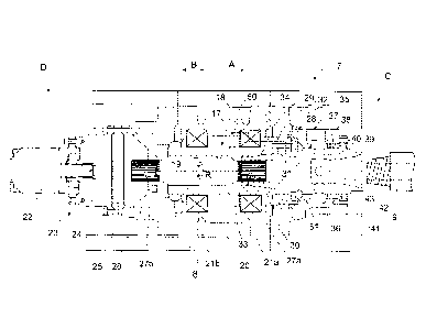
Figure 3 shows one possible embodiment of the rotation unit 7. The
rotation unit 7 has a main shaft 17, which comprises an outer shaft 18 and an
inner shaft 19. The outer shaft 18 has a tubular configuration and the inner
shaft
19 is arranged inside the outer shaft 18. The outer shaft 18 may be supported
to
a body 20 by means of two bearings 21a and 21b, which may serve as radial and
axial bearings. The bearings 21a and 21b are located at an axial distance from
each other and they may be roller bearings. The rotation unit 7 further
comprises
at least one rotation motor 22 for producing needed rotation movement and
torque. Rotation may be transmitted by means of transmission member 23 to the
inner shaft 19. The transmission member 23 may comprise a gear system 24,
such as a planetary gear, which may be connected to rotate the inner shaft 19
through modules 25 and 26, which may comprise suitable transmission
elements. At a front end C and rear end D of the inner shaft 19 there are
rotation
transmission portions, which may comprise splines 27a and 27b, a set of
grooves, or corresponding rotation transmission member. Rotation R and torque
is transmitted through the inner shaft 19 to a rotation hub 28 connected at a
front
end C of the main shaft 17. The rotation hub 28 may serve as an adaptor piece
between the main shaft 17 and drilling equipment 9. However, it is also
possible
that the drilling equipment 9 is provided with suitable connection surfaces
and
elements allowing it to be connected directly to the rotation unit, whereby no
need for the rotation hub exists.
CA 2905472 2016-10-14
CA 02905472 2015-09-29
9
The rotation hub 28 comprises at its rear end means for receiving
rotation R and torque from the inner shaft 19 and means for fastening to the
outer shaft 18 axially. The rear end portion of the rotation hub 28 may com-
prise a rear sleeve portion 29, which may be arranged inside the front portion
of the outer shaft 18 and comprises longitudinal splines 30, or corresponding
elements, on an inner surface of the rear sleeve portion 29. The splines 30 of
the rotation hub are in contact with splines 27a of the inner shaft 19. The
rota-
tion hub 28 may comprise a first axial fastening surface 31 for fastening the
rotation hub 28 to a second axial fastening surface 32 of the outer shaft 18.
The rotation hub 28 and the outer shaft 18 may comprise flanges 34 and 35
provided with the opposing axial fastening surfaces 31 and 32. The fastening
surfaces 31 and 32 may be fastened to each other by means of connection
screws 51, for example. However, any other suitable fastening arrangements
and means may also be utilized. As can be seen in Figure 3, the rear sleeve
portion 29 is located in annular space formed between an inner surface of the
outer shaft 18 and an outer surface of the inner shaft 19. Further, a
connecting
point 33 between the inner shaft 19 and the rotation hub 28 is located inside
the outer shaft 18, because the front end of the inner shaft 19 is located at
a
distance from the front end of the outer shaft 18.
The flange 34 at the front end of the outer shaft 18 may also trans-
mit axial forces via the bearings 27a, 27b to the body 20. Alternatively, the
outer surface of the outer shaft 18 may be provided with one or more shoul-
ders, protrusions or other axial surfaces serving as force transmitting
surfaces.
In Figure 3 a broken line 50 illustrates how the axial forces are transmitted
in
the disclosed structure. The bearings 21a and 21b may be configured to sup-
port the outer shaft 18 to the body 20 without axial clearance, whereby no
slid-
ing exists in the connecting point 33. Thus, wearing of the rotation
transmitting
elements may be decreased.
Figure 3 further shows that around the rotation hub 28 may be a
= 30
frontal housing 36 allowing feeding of a pressure medium to the drilling
equip-
ment 9. The housing 36 may comprise a feed port 37 and an inner space 38,
and the rotation hub 28 may comprise a central channel 39 and one or more
transverse channels 40. The pressure medium may be fed through the feed
port 37 to the inner space 38 and via transverse channels 40 to the central
channel 39. The drilling equipment 9 may be a drilling tube whereby it
receives
the pressure medium fed through the central channel 39. At a front end of the
CA 02905472 2015-09-29
housing 36 may be a cover 41, which closes the housing. Drilling equipment 9
may comprise connecting threads 42 and the front end of the rotation hub 28
may be provided with mating connecting threads 43.
Figure 4 illustrates dismantling of the rotation unit 7 shown in Figure
5 3. In case
the inner shaft 19 needs to be inspected or changed, it can be dis-
mantled without the need to dismantle the whole structure of the rotation unit
7.
During the dismantling the rotation unit 7 may remain fastened to the carrier
8
and only the frontal components, such as the cover 41, the housing 36 and the
rotation hub 28 needs to be removed. Thereafter the inner shaft 19 can freely
10 be pulled
out. There is no need to remove the outer shaft 18. Furthermore, the
rotation motor 22, and the transmission member 23 may be removed and ser-
viced without the need to dismantle the main shaft. Thanks to these features,
servicing of the rotation unit may be executed fast and easy at a drilling
site.
Figure 5 discloses a main shaft 17 comprising an outer shaft 18 and
an inner shaft 19. The outer shaft 18 may comprise a flange 34 at a front end
C of the main shaft 17. The outer shaft 18 may have a maximum outer diame-
ter D1 at the flange 34. The inner shaft may have a maximum diameter D2 be-
tween the splined portions 27a and 27b. The diameter D1 may be dimensioned
to at least double relative to the diameter D2. Figure 5 further shows that be-
tween front ends of the inner shaft 19 and outer shaft 18 may be a distance L,
which may be one third of the diameter D2, for example. Figure 5 also shows
that the outer shaft 18 is dedicated for transmitting axial forces FA, whereas
the inner shaft 19 is dedicated to transmit rotation R and torque.
Figure 6 discloses another main shaft structure, which deviates from
the one shown in Figure 5 only in such a way that the inner shaft 19 is not a
solid piece. Instead the inner shaft 19 comprises a longitudinal channel 44,
which extends from a front end to a rear end of the inner shaft 19. The
channel
44 offers a passage through which pressure medium fluid may be fed. Alterna-
tively, the channel may be utilized in conveyance of drilling samples.
Figure 7 discloses yet another main shaft structure, which deviates
from the one shown in Figure 5 only in such a way that between the inner shaft
19 and the outer shaft 18 is a longitudinal annular channel 45. The channel 45
may be used for feeding pressure medium fluid through the main shaft 17.
It should be noted that in the above embodiments the rotating mo-
tor may a hydraulic motor or an electric motor. Further, a direct drive motor
CA 02905472 2015-09-29
11
may also be used in the rotation units 7 shown in Figures 3 and 4, in which
case, deviating from the solutions of the figures, they have no gear system.
In some cases, features disclosed in this application may be used
as such, regardless of other features. On the other hand, when necessary, fea-
tures disclosed in this application may be combined in order to provide
various
combinations.
The drawings and the related description are only intended to illus-
trate the idea of the invention. Details of the invention may vary within the
scope of the claims.