Note: Descriptions are shown in the official language in which they were submitted.
ABSORBENT ARTICLES AND METHODS OF MANUFACTURING THE SAME
[00011
BACKGROUND
100021 The present invention relates generally to absorbent articles
and, in particular,
to absorbent articles having improved fit, comfort and manufacturability.
[003] Millions of people of all ages suffer from incontinence of the
bowel or
bladder. Whether an infant, adult, or elderly person, the underlying cause of
incontinence
varies but the method of treatment typically involves absorbent article
products. Adult
incontinent briefs, disposable diapers and underpads can alleviate some of the
emotional and
physical discomfort of incontinence by absorbing and containing liquid and
other discharges
from the human body to prevent body and clothing soiling.
[0004] Despite recent pressure from Center for Medicaid and Medicare
Services
(CMS) to change clinical practice to promote systematic treatment of
incontinence, improper
use of absorbent incontinent products for the management of urinary and fecal
incontinence
1
CA 2905702 2019-08-12
CA 02905702 2015-09-11
WO 2014/149446
PCT/US2014/018500
continues. The high prevalence of incontinence in nursing home residents
results in
Incontinence Associated Dermatitis (IAD) in the perineal area and is a common
complication. Improper fit or use, applying the wrong size to a user, of
absorbent articles is a
contributing factor to perineal dermatitis by creating increase heat build-up
or chafing against
the superficial skin tissue.
100051 In an
attempt to improve performance and reduce abrasion to the skin, the
absorbent articles industry has been introducing new product concepts with,
for example,
non-woven back sheets for better comfort. However, these products still
contribute to the
development of IAD due to the improper size and design in the crotch chaises
and leg cut out.
In an attempt to size the garments appropriately, a majority of current
absorbent articles are
sold in five sizes: Medium, Regular, Large, Extra Large and 2X Large. These
sizes however
do not resolve the above issues as the articles do not sufficiently
accommodate users with
different body size proportions. As a result caregivers constantly need to use
a larger,
oversized garment because the product design does not allow for good fit
around the patients
waist and thigh leg area at the same time. Thus, caregivers are placing larger
garments on the
patient to compensate which leads to higher cost; potential leakage; and lower
dignity
because of a bigger bulky garment being worn.
100061 Further, not
using the correct size garment on a patient who suffers from
incontinence violates the federal governments CMS-F315 rules that require care
professionals
and staff to use the correct size and type of garment based on the patient's
condition and size.
100071
Additionally, multiple sizes are created by multiple size components leading
to inefficient manufacturing process. Each size requires the manufacturer to
stop the machine
and change out a number of the machine's sections in order to produce the next
size. After
changing the machine sections, other sections need to be recalibrated in order
to insure the
raw material components are converted correctly. These changeovers can take
anywhere
2
CA 02905702 2015-09-11
WO 2014/149446
PCT/US2014/018500
between 6 to 12 hours depending on the machine being used by the manufacturer.
This
downtime reduces the amount of product the machine can produce and increases
the
manufacturers converting cost. Further, current adult brief machines
manufactures are
required to use extra steel and other materials in order to build the
additional components for
the additional sizes.
100081 In another
attempt to improve performance and fit, incontinence articles are
configured with stretchable material attached to the back panel of the
article's ears. However
the stretch briefs have shorter front panels in order to offset the cost of
stretch material. First
this requires the caregiver to use a different application technique because
the attachment
zone is smaller. Second, the stretch material, when extended fully to
accommodate a larger
waist for patients who at the upper limit of sizing, can cause skin irritation
and breakdown,
particularly in the waist and hip region. Often the waist securement portions
are over-
stretched and incorrectly fit, traumatizing the skin as it lays adjacent to.
100091 In an
attempt to improve the performance of an absorbent layer of the
incontinence article, the top of a core of the absorbent layer can be
embossed. Embossing the
top of the absorbent layer can increase the lateral movement of fluid that
comes in contact
with the absorbent layer and can reduce leakage, but can also increase
circular movement of
the fluid and increase leakage. Similarly, absorbent layers having two cores
have similar
advantages and disadvantages. In addition, flow between the top core and the
bottom core
can be insufficient, even when the top of the bottom core is embossed.
100101 In addition,
when donning the product, significant forces may be subjected
upon the side panels, especially while the product is being applied and the
wearer's body
weight is directly on the chassis of the absorbent article. These forces can
be localized along
one edge of the article, and therefore can cause a failure, for example, a
tear in the panel,
3
CA 02905702 2015-09-11
WO 2014/149446
PCT/US2014/018500
which propagates quickly and completely across the span of the panel, thereby
causing a
complete failure of the article.
100111
Additionally, a patient with skin care concerns in the hip region may benefit
from a product that can provide softness and a more comfortable side panel.
Additionally, as
adult brief products have evolved, these products now include side panels that
are used for
closure. As these side panels are used, it is possible for the wearer to don
the product in such
a way that the side panel can bunch, and cause pressure lines against the
wearer.
Additionally, when the product is manufactured, the process of applying the
side panel to the
diaper includes a manufacturing step of folding a portion of the side panel.
If elements of the
manufacturing process are not ideal, scrap can be created in the manufacturing
process.
100121 Accordingly,
a need exists for absorbent articles that provide a better fit and
comfort, and increased absorption, while reducing the number of sizes within a
range of
products, reducing manufacturing costs, and reducing the impact on the
environment. A need
also exists for absorbent articles that will resist bunching, while at the
same time providing
softness and the effect of padding for the wearer. A further need exists to
improve the ability
to fold this side panel during the manufacturing process.
BRIEF DESCRIPTION OF THE DRAWINGS
100131 The
foregoing and other advantages of the invention will become apparent
upon reading the following detailed description and upon reference to the
drawings.
100141 FIG. 1
illustrates a top view of absorbent article in a first configuration
according to one embodiment.
100151 FIG. 2A-B
illustrates a top view of a first absorbent article and a second
absorbent article in the first configuration according to one embodiment.
4
CA 02905702 2015-09-11
WO 2014/149446
PCT/US2014/018500
100161 FIG. 3A-B illustrates a top view of a third absorbent article and a
fourth
absorbent article in the first configuration according to one embodiment.
100171 FIG. 4 illustrates a perspective view of an absorbent article in a
second
configuration.
100181 FIG. 5 illustrates a side view of an absorbent article in a third
configuration.
100191 FIG. 6 illustrates a front securement portion coupled to a back
securement
portion according to one embodiment.
100201 FIG. 7 illustrates a securement portion having an elastic panel
according to
one embodiment.
100211 FIG. 8 illustrates a wearer including an absorbent article in the
third
configuration according to one embodiment.
100221 FIG. 9 illustrates a wearer including an absorbent article in the
third
configuration according to another embodiment.
100231 FIG. 10 illustrates an exploded view of the absorbent article shown
in FIG. 1.
100241 FIG. 11 illustrates a perspective view of a second core of the
absorbent article
depicted in FIG. 1.
100251 FIG. 12 illustrates a perspective view of a first core of the
absorbent article
depicted in FIG. 1.
100261 FIG. 13 illustrates a cross-section of an end view of a portion of
an absorbent
article according to an embodiment.
100271 FIG. 14 illustrates a cross-section of an end view of a portion of
an absorbent
article according to an embodiment.
100281 FIG. 15 illustrates a cross-section of an end view of a portion of
an absorbent
article according to an embodiment.
CA 02905702 2015-09-11
WO 2014/149446
PCT/US2014/018500
100291 FIG. 16
illustrates a cross-section of a side view of a portion of the absorbent
article shown in FIG. 15.
100301 FIG. 17
illustrates a securement portion having a lamination layer according to
one embodiment.
100311 FIG. 18
illustrates a securement portion having a lamination layer according to
a further embodiment.
100321 FIG. 19
illustrates a securement portion having a lamination layer according to
a further embodiment.
100331 FIG. 20
illustrates a cross section of securement portion having a lamination
layer according to the embodiment of FIG. 19.
100341 FIG. 21
illustrates a securement portion having a lamination layer according to
a further embodiment.
100351 FIG. 22
illustrates a cross section of securement portion having a lamination
layer according to the embodiment of FIG. 21.
100361 FIG. 23
illustrates a securement portion having a lamination layer according to
a further embodiment.
100371 FIG. 24
illustrates a cross section of a folded absorbent article having a
securement portion according to the embodiment of FIG. 23.
100381 FIG. 25
illustrates an embodiment of a bonding pattern for a securement
portion having a lamination layer.
100391 FIG. 26
illustrates a top view of an embodiment of an absorbent article
including a sacral lamination layer.
100401 FIG. 27
illustrates a schematic of a portion an embodiment of a method for
manufacturing an absorbent article with a rear side panel in accordance with
embodiments
shown in FIGS. 17-25.
6
CA 02905702 2015-09-11
WO 2014/149446
PCT/US2014/018500
100411 FIG. 28
illustrates a schematic of a further portion an embodiment of a method
for manufacturing an absorbent article with a rear side panel in accordance
with embodiments
shown in FIGS. 17-25.
100421 FIG. 29
illustrates a schematic of a further portion an embodiment of a method
for manufacturing an absorbent article with a rear side panel in accordance
with embodiments
shown in FIGS. 17-25.
100431 While the
invention is susceptible to various modifications and alternative
forms, specific embodiments have been shown by way of example in the drawings
and will
be described in detail herein. It should be understood, however, that the
invention is not
intended to be limited to the particular forms disclosed. Rather, the
invention is to cover all
modifications, equivalents, and alternatives falling within the spirit and
scope of the
invention.
DESCRIPTION OF ILLUSTRATIVE EMBODIMENTS
100441 Absorbent
articles as described herein generally include a moisture-pervious
inner layer, an absorbent layer, and a moisture-impervious outer layer.
Although the
remainder of the description will be specifically directed to adult
incontinence articles, a
disposable diaper, it is to be understood that the embodiments may also be
implemented on
other absorbent articles, baby diapers for example, and that the properties
and uses described
below apply to these other absorbent articles as well.
100451 Embodiments
of the invention are now described in detail. Referring to the
drawings, like numbers indicate like parts throughout the views. As used in
the description
herein and throughout the claims, the following terms take the meanings
explicitly associated
herein, unless the context clearly dictates otherwise: the meaning of "a,"
"an," and "the"
7
CA 02905702 2015-09-11
WO 2014/149446
PCT/US2014/018500
includes plural reference, the meaning of "in" includes "in" and "on."
Relational terms such
as first and second, top and bottom, and the like may be used solely to
distinguish one entity
or action from another entity or action without necessarily requiring or
implying any actual
such relationship or order between such entities or actions. Also, reference
designators
shown herein in parenthesis indicate components shown in a figure other than
the one in
discussion. For example, talking about a device (10) while discussing figure A
would refer to
an element, 10, shown in figure other than figure A.
100461 In some
embodiments, an absorbent article includes a chassis. The chassis has
a substantially rectangular shape including a length extending in a
longitudinal direction from
the back to the front of a user and a width extending in a lateral direction
substantially
perpendicular to the length between first and second longitudinal edges. The
chassis further
includes a first portion, a second portion and a crotch portion extending
between the first and
second portion, a portion of the chassis being configured to absorb fluids.
The absorbent
article includes a first securement portion operatively coupled to the first
portion of the
chassis, the first securement portion having a width extending in a lateral
direction from the
first longitudinal edge of the chassis first portion and a length extending
longitudinally along
the first longitudinal edge. The absorbent article includes a second
securement portion
operatively coupled to the second portion of the chassis in a position
longitudinally spaced
from the first securement portion and configured to releasably attach to the
first securement
portion. The chassis is configured to include one of a first chassis length or
a second chassis
length. When the chassis includes the first length, the chassis includes a
first width and the
first securement portion includes a second width, and when the chassis
includes the second
length, the chassis includes the first width and the first securement portion
includes a third
width, 0-eater than the second width..
8
CA 02905702 2015-09-11
WO 2014/149446
PCT/US2014/018500
100471 In some
embodiments, an absorbent article includes a chassis. The chassis
including a length extending in a longitudinal direction from the back to the
front of a user
and a width extending in a lateral direction substantially perpendicular to
the length between
first and second longitudinal edges. The chassis comprises a first portion, a
second portion
and a crotch portion extending between the first and second portion, a portion
of the chassis
being configured to absorb fluids. The absorbent article includes a first
securement portion
operatively coupled to the first portion of the chassis, the first securement
portion having a
width extending in a lateral direction from the first longitudinal edge of the
first portion of the
chassis and a length extending longitudinally along the first longitudinal
edge. The absorbent
article includes a second securement portion having a stretch portion and a
non-stretch
portion, the second securement portion operatively coupled to the second
portion of the
chassis in a position longitudinally spaced from the first securement portion
and configured
to releasably attach to the first securement portion. The chassis configured
to include one of
a first length or a second length. When the chassis includes the first length,
the stretch
portion of the second securement portion includes a first width and the non-
stretch portion of
the second securement portion includes a second width, and when the chassis
includes the
second length, the stretch portion of the second securement portion includes
the first width
and the non-stretch portion of the second securement portion includes a third
width, greater
than the second width..
100481 In some
embodiments, a system of absorbent articles to ensure a properly
fitting absorbent article includes a first absorbent article and a second
absorbent article. The
first absorbent article has a first width and a first length along a
longitudinal edge. The first
absorbent article includes a first portion, a second portion, and a crotch
portion extending
between the first and second portion. The first absorbent article includes a
securement
portion operatively coupled to the first portion, the securement portion
having a width
9
CA 02905702 2015-09-11
WO 2014/149446
PCT/US2014/018500
extending in a lateral direction from the longitudinal edge of the first
portion and a length
extending longitudinally along the longitudinal edge. The second a second
absorbent article
has the first width and a second length along a longitudinal edge. The second
absorbent
article includes a first portion, a second portion, and a crotch portion
extending between the
first and second portion. The second absorbent article includes a securement
portion
operatively coupled to the first portion, the securement portion having a
width extending in a
lateral direction from the first longitudinal edge of the first portion and a
length extending
longitudinally along the first longitudinal edge.
100491 Other features further provide leg openings that are more generous
as a result
of the rectangular chassis, rectangular body securement portion configuration
allowing for a
more accurate fit to accommodate a wide range of body types per article size.
Front panels
are configured to underlay the back panels providing a more comfortable fit
and reduced skin
degradation and trauma to the wearer.
100501 FIG. 1 illustrates in plan view, an exemplary non-limiting general
embodiment
of an absorbent article 100 in a substantially flat un-contracted state (the
first configuration),
having a reduced component configuration that accommodates multiple sized
wearers. In
this embodiment the article comprises a chassis 102, securement portions 104,
106, 108, 110,
a first core portion 116, and a second core portion 118. Although not shown in
this figure,
the absorbent article 100 may include a set of leak guards and/or a set leg
cuffs 142, 144, both
known to those of ordinary skill in the art. In this embodiment there are four
body
securement portions comprising a first securement portion 104, a second
securement portion
106, a third securement portion 108, and a fourth securement portion 110. It
should be noted
that four securement portions are used in this embodiment however it should be
recognized
that other embodiments may be configured with more or fewer securement
portions.
CA 02905702 2015-09-11
WO 2014/149446
PCT/US2014/018500
100511 The
absorbent article 100 generally consists of several layers (see, e.g., FIG.
10), including an inner layer, an absorbent layer, and an outer layer. The
inner layer faces a
wearer and contacts the skin of the wearer when the absorbent article 100 is
secured to the
wearer. The inner layer may be composed of a moisture-pervious fabric suitable
to allow
bodily discharge to pass through the inner layer and be absorbed by the
absorbent layer.
Non-limiting examples of materials suitable to form the inner layer include
polypropylene,
polyethylene, polyester, materials having hydrophobic properties, combinations
thereof
and/or the like. Additionally, the inner layer can be treated with a
hydrophilic finish to
improve pass through of liquids to diaper layers beneath the inner layer. Non-
limiting
examples of suitable hydrophilic finishes include stearic acid, melamine-based
chemicals,
fluorocarbon chemicals, and silicon based chemicals.
100521 The
absorbent article 100 generally has a back region 150 and a front region
160. First securement portion 104 and second securement portion 106 are
coupled to and
may extend from the back region 150, and third securement portion 108 and
fourth
securement portion 110 are coupled to and may extend from the front region
160. The back
region 150 is generally positioned against the back of the user. The front
region 160 is
generally positioned against the front of the user. The third securement
portion 108 and the
fourth securement portion 110 are configured to wrap around a wearer's waist
from front to
back, and the first securement portion 104 and the second securement portion
106 are
configured to wrap around a wearer's waist from back to front. In this manner,
first
securement portion 104 and second securement portion 106 can be coupled to
third
securement portion 108 and fourth securement portion 110, respectively, to
couple the front
region 160 to the back region 150.
100531 The
absorbent article 100 in this illustration of FIG. 1 is shown with the
portion of the absorbent article 100 that contacts the wearer shown facing the
viewer. The
11
CA 02905702 2015-09-11
WO 2014/149446
PCT/US2014/018500
absorbent article 100 includes a longitudinal axis 101 and a lateral axis 103.
The absorbent
article 100 includes a first end portion 105, a second end portion 107, and an
intermediate
portion 109. The first end portion 105 is also referred to herein as a front
waist region 105,
the second end portion 107 is also referred to herein as a back waist region
107, and is
substantially opposite the first end portion 105, and the intermediate portion
109 is also
referred to herein as a crotch region 109, and is disposed longitudinally
between the front and
back waist regions 105 and 107. The front waist region 105 and the back waist
region 107
generally comprise those portions of the absorbent article 100 which, when
worn, encircle the
waist of the wearer. The crotch region 109 is that portion of the absorbent
article 100 which,
when the absorbent article 100 is worn, is generally positioned between the
legs of the
wearer. The back securement portions 104 and 106 and the front securement
portions 108
and 110, are separated by distance Li 114. This distance Li 114 defines a
portion of the leg
opening.
100541 The
article's chassis 102 has a chassis width "CW' 112, and a chassis length
"CL" 111. The chassis width 112 is a common width across all article sizes
that
accommodate a plurality of body sizes. Stated in a different way, the
absorbent article 100
has a multi-article-size-accommodating width 112 and a multi-article-size-
accommodating
length 111. Still, put in other words, one chassis width 112 is used for
different sized brief
articles while still accommodating different wearer's body sizes. By way of
example, there
are two lengths of the chassis, as illustrated in FIG. 2 and FIG. 3 in
combination with FIG.1,
a first chassis length CL 211a, 211b for a first article size and a second
article size, in this
embodiment a Medium size and a Regular size, and a second chassis length CL
311a 311b
for a third article size and a fourth article size, for example a Large size
and a X-Large size in
this embodiment.
12
CA 02905702 2015-09-11
WO 2014/149446
PCT/US2014/018500
100551 The chassis
102 has a shape such that its outer perimeter is rectangular or at
least substantially rectangular in the first configuration in this embodiment
the absorbent
article 100 has at least one securement portion that is coupled to the chassis
102 at one of the
front waist region 105 or the back waist region 107. In other embodiment,
there may be
portions of the chassis that are shaped and/or removed, such as in the crotch
region 109, for
example, resulting in a narrower crotch region portion 109 to provide a
contoured fit between
the legs. Still other embodiments have different shaped chassis, such as hour
glass shapes, T-
shapes, and the like.
100561 The first
securement portion 104 is coupled to a first longitudinal side edge
portion 113 of the chassis, the first securement portion 104 overlapping the
chassis 102 along
the lineal contact points of attachment 132. The amount of overlap is
sufficient to reliably
attach the securement portion to the chassis such that there is no separation
during use, as
would be understood to one of ordinary skill in the art. In one embodiment,
the overlap of
the first securement portion 104 with the chassis 102 longitudinal side edge
113 is between
6mm and 50mm (or about 0.25 inches and 2.0 inches). In this embodiment, the
overlap of
the securement portion with the chassis is generally the same for all four
securement portions.
First securement portion 104 includes two fasteners 120. Fasteners 120 can be
configured to
operatively couple first securement portion 104 to third securement portion
108 and/or to
anywhere along the front region 105. While FIG. 1 depicts first securement
portion 104 as
including two fasteners 120, in some embodiments, first securement portion 104
can include
more or fewer fasteners. While FIG. 1 depicts fasteners 120 sized and shaped a
particular
way, in other embodiments, fasteners 120 can be a different size and/or shape,
such as, for
example, similar to fastener 762 as depicted in FIG. 7.
100571 The second
securement portion 106 is coupled to the second longitudinal side
edge portion 115 of the chassis, the first securement portion 106 overlapping
the chassis 102
13
CA 02905702 2015-09-11
WO 2014/149446
PCT/US2014/018500
along the lineal contact points of attachment 130, in the same manner as the
first securement
portion 104. Together, the first securement portion 104, the back waist region
of the chassis
107, and the second securement portion 106, laterally form the overall width
"OW07 170 of
the article at the back region. The first securement portion 104 has a first
width 1)1 122 and
the second securement portion 106 has a second width P, 124. Second securement
portion
106 includes two fasteners 120. Fasteners 120 can be configured to operatively
couple
second securement portion 106 to fourth securement portion 110 and/or to
anywhere along
the front region 105. While FIG. 1 depicts second securement portion 106 as
including two
fasteners 120, in some embodiments, second securement portion 106 can include
more or
fewer fasteners. While FIG. 1 depicts fasteners 120 sized and shaped a
particular way, in
other embodiments, fasteners 120 can be a different size and/or shape, such
as, for example,
similar to fastener 762 as depicted in FIG. 7.
100581 In some
embodiments, the first securement portion 104 and the second
securement portion 106 can be coupled to the chassis 102 in the following
manner. An end
portion 131 of first securement portion 104 can be temporarily coupled to and
end portion
129 of second securement portion 106. In some of these embodiments, end
portion 131 can
overlap end portion 129 and can be temporarily coupled to end portion 129 via
an adhesive.
In other of these embodiments, end portion 131 can be temporarily coupled to
end portion
129 via a perforated seem (not shown) between end portion 129 and end portion
131.
Chassis 102 can be temporarily coupled to first securement portion 104 and
second
securement portion 106. Specifically, the back waist region 107 of the chassis
102 can be
disposed substantially on top of the end portion 129 of the first securement
portion 104 and
the end portion 131 of the second securement portion 106. Said another way,
end portion 129
of first securement portion 104 and end portion 131 of second securement
portion 106 can be
disposed on a first side of chassis 102. At least a portion of first
securement portion 104 can
14
CA 02905702 2015-09-11
WO 2014/149446
PCT/US2014/018500
be folded over chassis 102 such that first securement portion 104 can be
operatively coupled
to chassis 102 approximately at lineal contact points 132 as described above.
At least a
portion of second securement portion 106 can be folded over chassis 102 such
that second
securement portion 106 can be operatively coupled to chassis 102 approximately
at lineal
contact points 130 as described above. End portion 129 and end portion 131 can
be released
from contact with the other of end portion 129 and end portion 131.
100591 The third
securement portion 108 is coupled to a third longitudinal side edge
portion 119 of the chassis, the third securement portion 108 overlapping the
chassis 102
along the lineal contact points of attachment 134. The amount of overlap is
sufficient to
reliably attach the securement portion to the chassis such that there is no
separation during
use, as would be understood to one of ordinary skill in the art.
100601 The fourth
securement portion 110 is coupled to the fourth longitudinal side
edge portion 121 of the chassis, the first securement portion 110 overlapping
the chassis 102
along the lineal contact points of attachment 136, in the same manner as the
first, second or
third securement portion 104, 106, 108. Together, the third securement portion
108, the front
waist region of the chassis 105, and the fourth securement portion 110,
laterally form the
overall width "OWb" 180 of the absorbent article 100 at the back region. The
third
securement portion 108 has a third width P3 126 and the fourth securement
portion 110 has a
fourth width P4 128. In this embodiment all four securement portion widths Pi
¨ P4 are
substantially the same.
100611 Third
securement portion 108 and fourth securement portion 110 can be
operatively coupled to the chassis 102 via temporary coupling of end portion
138 of third
securement portion 108 and end portion 139 of fourth securement portion 110 in
a manner
similar to that described above with reference to first securement portion 104
and second
securement portion 106.
CA 02905702 2015-09-11
WO 2014/149446
PCT/US2014/018500
100621 In other
embodiments the width of the securement portions may vary from
portion to portion as well as from front to back or side to side. For example,
the first
securement portion 104 and the second securement portion 106 may have a
substantially
equal width but a different width than the third securement portion 108 and
the fourth
securement portion 110. In another embodiment the first securement portion and
the second
securement portion are one continuous piece, running across the entire chassis
in a
perpendicular fashion and extending beyond the edges of the chassis, forming
the body
securement portions. In another embodiment the third securement portion and
the fourth
securement portion are one continuous piece, running across the entire chassis
in a
perpendicular fashion and extending beyond the edges of the chassis, forming
the body
securement portions. In one embodiment the overall width of the back region
"OWa7 170,
including the first securement portion 104, the chassis 102 and the second
securement portion
106 stays the same, and similarly the overall width of the front region "OWL,"
180, including
the third securement portion 108 the chassis 102 and the fourth securement
portion 110 stays
substantially the same.
100631 In one
embodiment the chassis 102 has a common chassis width CW 112
between 190mm and 350mm and preferably about 320mm for all article sizes (the
first size
article, the second size article, the third size article and the fourth size
article). In this
embodiment the width of each securement portion (P,) is the same at the back
region end 150
as it is in the front region end 160. For all article sizes (e.g. medium,
regular, large extra
large), the chassis width 112 is the same. In this embodiment the chassis 102
has a
rectangular shape or a substantially rectangular shape, wherein the width is
the short
dimension. For the first article size and the second article size, the chassis
102 may also have
a first common chassis length CL 111 which in this embodiment is between 800mm
and
880mm and preferably 860mm. For the third article size and the fourth article
size, the
16
CA 02905702 2015-09-11
WO 2014/149446
PCT/US2014/018500
chassis 102 may have a second common chassis length CL 111, different from the
first
common chassis length, and in this embodiment is between 860mm to 1000mm and
preferably 960mm. The Chassis length CL 111 in this figure refers to the
dimension and not
the actual value.
100641 As shown in
FIG. 1, the edge 199 of chassis 102 can be substantially flush
with edge 117 of portion 104 and portion 106. In some embodiments, the edge
199 can
extend beyond the edge 117 of portion 104 and portion 106 (see, e.g., FIG. 4).
100651 The articles
are assembled together in the manufacturing process such that the
body securement portions are secured to the chassis 102 wherein the panels
104, 106, 108
and 110 are disposed between a first chassis layer, for example a top sheet,
and a second
chassis layer, for example a bottom sheet. The machine assembling the article
is set such that
the panel widths are changed from a first width to a second width in order to
change over
from building a first article size 201 to a second article size 202.
Similarly, when changing
over to a third article size, the panel widths are increased, and additionally
in this
embodiment, the chassis length is increased to the second chassis length as
for the third
article size 303 and fourth article size 304. For these changes, the
changeover is completed
by running different programs in the machine and minimal or even zero hard
tooling change
over is required. By way of example, there may be no hard tool changeovers
such as the
replacement of cutting dies which are typically used for cutting leg openings.
Instead, only
vacuum plate changes may be needed for the size changes in the panel widths
and length
which are relatively simple replacements. In some embodiments, the vacuum
plates need not
even be physically replaced, the vacuum plates are sized to accommodate all
sizes of panels
and depending on the size of the panel, and vacuum ports are enabled or
disable based on the
size of the panel.
17
CA 02905702 2015-09-11
WO 2014/149446
PCT/US2014/018500
100661 FIG. 2 and
FIG. 3 illustrate together, in plan view fashion, an exemplary non-
limiting general embodiment of four different sized absorbent articles, in the
flat un-
contracted state. The first absorbent article 201 configured as a first wearer
size and the
second absorbent article 202 configured as a second wearer size are shown in
FIG. 2. The
third absorbent article 303 sized as a third wearer size and the fourth
absorbent article 304
sized as a fourth wearer size are shown, in their flat un-contracted state, in
FIG. 3. The
different wearer sizes, the first and second articles 201, 202 are created by
configuring the
securement portion widths, e.g. Pl, P2 or both, for the first wearer size 201
and the second
wearer size 202 in order to accommodate different wearer waist sizes, all with
the same
chassis width 212 and chassis length 211a and 211b. For example, the first
size article 201
will have a fixed chassis width "CW" of about 320mm and first, second, third
and fourth
securement portion individual widths of about 180mm, while the second size
article will have
first, second, third and fourth securement portion widths of about 200mm,
however still with
the chassis width "CW" of 320mm. The chassis length 211a and 211b, are about
860mm for
the first and second articles 201, 202.
100671 In this
embodiment, using the first size article 201 as an example, the
securement portion width "Px" may be maintained the same for each securement
portion 204,
206, 208, 210 or in another embodiment the first securement width 204 may be a
different
width than the second securement portion width 206, while maintaining the same
overall
width 203 of the rear portion of the article. In yet another embodiment the
first and second
securement portions 204, 206, may have a first width, and the third and fourth
securement
portions 208, 210 may have a second width.
100681 For the
third size 303 and the fourth size 304 (FIG. 3), the chassis width 311a
and 311b "CW" of about 320mm, remains the same as the first and second sizes,
however the
securement portion widths "P," and the chassis lengths "CL" 111 are configured
differently
18
CA 02905702 2015-09-11
WO 2014/149446
PCT/US2014/018500
from the first size 201 and the second size 202 to accommodate the different,
greater in this
embodiment, article sizes. The third size article 303 will have a fixed
chassis width "CW" of
about 320mm and first, second, third and fourth securement portion widths of
about 255mm,
while the fourth size article 304 will have first, second, third and fourth
securement portion
widths of about 275mm. The chassis length, 311a and 311b may be between 860mm
and
1000mm and in one embodiment the chassis length 311a and 311b, is about 960mm
for the
first and second articles 201, 202.
100691 As with the
first and second article sizes 201, 202, the securement portion
width "Ps" may be maintained the same for each securement portion 304, 306,
308, 310 or in
another embodiment the first securement portion 304 width may be a different
width than the
second securement portion width 306, yet while maintaining the same overall
width "OWa"
301 of the article at the back end or the same overall width "OWb" 302 of the
article at the
front end. In yet another embodiment the first and second securement portions
304, 306, may
have a first width, and the third and fourth securement portions 308, 310 may
have a second
width. As the width of the first and second portions increases, the width of
the third and
fourth portion may decrease, so long as there is overlap in accordance with
the size of the
article to fit the wearer.
100701 In the
embodiment shown in FIG. 3, the third size article 303 will have a fixed
chassis width "CW" of about 320mm and first, second, third and fourth
securement portion
widths of about 255mm, while the fourth size article 304 will have first,
second, third and
fourth securement portion widths of about 275mm. The chassis length, 311a and
311b may
be between 860mm and 1000mm and in one embodiment the chassis length 311a and
311b, is
about 960mm for the first and second articles 201, 202.
100711 FIG. 4 is a
perspective view of an absorbent article 400 in a second
configuration. Absorbent article 400 can be similar to and include similar
components as
19
CA 02905702 2015-09-11
WO 2014/149446
PCT/US2014/018500
absorbent article 100. By way of example, absorbent article 400 includes
securement portion
404, 406, 408, and 410, which can be similar to securement portions 104, 106,
108, and 110,
respectively. The second configuration shows the chassis 402 in a position as
it would be
when placed on the wearer although the securement portions, 404, 406, 408 and
410 remain
in an un-contracted, unwrapped state. Securement portion 404 includes an edge
465,
securement portion 406 includes an edge 467, securement portion 408 includes
an edge 466,
and securement portion 410 includes an edge 469.
100721 FIG. 5 is a
side view of an absorbent article 500 in a third configuration.
Absorbent article 500 can be similar to and include similar components as
absorbent article
100. By way of example, absorbent article 500 includes securement portion 504
(not shown),
506, 508, and 510 (not shown), which can be similar to securement portions
104, 106, 108,
and 110, respectively. The third configuration shows the securement portions
in a wrapped
state, as they would be wrapped around a wearer. In this embodiment, the
securement
portions may be configured such that the second securement portion 506
overlaps the third
securement portion 508, and the first securement portion 504 overlaps the
fourth securement
portion 510. The third and fourth securement portions 508, 510, lay directly
adjacent the
wearer's skin, while the first securement portion 504 and the second
securement portion 506,
lie partially on the wearer's skin and partially on the third and fourth
securement portions
respectively. Having front securement portions that may wrap substantially up
to an in some
embodiments substantially past a person mid point and around towards and
against the
wearer's backside provides a more comfortable fit.
100731 The leg
opening 501, is defined by a bottom edge 570 of the securement
portions, a second securement portion 506 and a third securement portion 508,
and the
longitudinal edges portions 505 of the chassis 502, having the length Li 114
between the
securement portions along the longitudinal edge of the chassis 502. Because of
the
CA 02905702 2015-09-11
WO 2014/149446
PCT/US2014/018500
rectangular nature of the securement portions 506 and 508 for the first leg
opening, the
bottom edge 570 is significantly adjacent the waist and, is positioned higher
than or at least
significantly above the thigh of the wearer.
100741 FIG. 6
illustrates a front securement portion 608 and a back securement
portion 606. The front securement portion 608 can be similar to third
securement portion 108
and fourth securement portion 110, and back securement portion 606 can be
similar to first
securement portion 104 and second securement portion 106. The front securement
portion
has a length 674 and the back securement portion has a length 676. The length
of the front
securement portion 608 is greater than the length 676 of the back securement
portion. A
fastener 678 is coupled to the back securement portion 606. The length of the
front
securement portion 608 is greater than the length for the back securement
portion 606 to
move up or down during fastening and still provide a landing zone for the
fastener 678, such
that the fastener 678 does not come in contact with the wearer's skin. In this
embodiment,
the fastener 678 has substantially the same length as the back securement
portion 606 length
676. The fastener 678 in this embodiment may be applied to the back securement
portion
606 and cut to length during the formation of the back securement portion 606.
100751 FIG. 7
illustrates a securement portion 706, of a chassis 702, the securement
portion 706 including an elastic panel coupled thereto. Securement portion 706
can be
similar to and include similar components with first securement portion 104
and second
securement portion 106. In one embodiment, the securement portion 706 has a
first non-
elastic panel 752, a second non-elastic panel 754 and an elastic panel 756.
In one
embodiment, the elastic panel 756 is disposed between the first non-elastic
panel 752 and the
second non-elastic panel 754. Each panel has a first side edge and a second
side edge, distal
the first side edge, and a top edge 766 and a bottom edge 768, forming a
rectangle. The first
non-elastic panel 752 is attached to the chassis 702 at a first side edge of
the first non-elastic
21
CA 02905702 2015-09-11
WO 2014/149446
PCT/US2014/018500
panel 752 and to a first side edge of the elastic panel 756 at a second side
edge, distal the first
side edge. A second side edge of the elastic panel 756, distal the first side
edge, is coupled to
a first side edge of the second non-elastic panel 754. The second side edge
764, distal the
first side edge, has at least one fastener 762 coupled thereto. Securement
portion 706 is
coupled to the chassis 702 in a similar fashion to the securement portions
104, 106, 108, 110
as discussed above.
100761 A first seam
758 is formed by the first non-elastic panel 752 second side edge
joint with the first side edge of the elastic panel 756. A second seam 760 is
formed by the
second side edge of the elastic panel 756, joint with the first side edge of
the second non-
elastic panel 754.
100771 Having a
portion of the securement potion 706 include a stretchable material
allows for a single article to fit a greater number size rage of wearers. For
example in one
embodiment, only to article size are need to fit the same size range of wears
for the four
articles discussed above. This further reduces waste as there is a reduction
in the amount of
machinery need to build multiple size accommodating articles as well as less
change over
from product size to product size, thereby increasing efficiency in the
manufacturing process.
100781 In one
embodiment the elastic panel 756 has a width between 40mm and
100mm and preferably has a width of about 68mm in one embodiment for a first
article size.
The non-elastic portions may have equal widths which may be about 77mm for
example for
the first article size. For a second size in this embodiment, the elastic
panel 756 has a width
between 40mm and 100mm and preferably has a width of about 68mm in one
embodiment
for a first article size. The non-elastic portions may have equal widths which
may be about
108mm for example. There is an overlap of the non-elastic portion and the
elastic portion of
about 15mm in this embodiment. This overlap is where the two portions are
joined together.
22
CA 02905702 2015-09-11
WO 2014/149446
PCT/US2014/018500
In this embodiment, the two portions are glued together. One of ordinary skill
in the art will
understand the plurality of methods and procedures for affixing the portions
together.
100791 The stretch
material may be made from stretch material as understood by those
of ordinary skill in the art. In one embodiment the stretch material is a 107
GSM stretch
material by 3M.
100801 FIG. 8
illustrates a further embodiment of an absorbent article 800 as used by
a wearer. The absorbent article can include a chassis 802. In this embodiment
a front
securement portion 808 wraps around the wearer from front to back and lays
underneath the
back securement portion 806. The back securement portion 806 can overlap the
front
securement portion 808 a distance 880. Front securement portion 808 can be
similar to and
include similar components with third securement portion 108, fourth
securement portion
110, and front securement portion 708. Similarly, back securement portion 806
can be
similar to and include similar components with first securement portion 104,
second
securement portion 106 and back securement portion 706. In this embodiment the
front
securement portion 808 length 874 is greater than the back securement portion
806 length
882. The back securement portion 806 includes an elastic panel 856 disposed
between a first
non-elastic panel 852 and a second non-elastic panel 854, and includes a
fastener 862 similar
to fastener 762 and fastener 678. A first seam 858 is formed by the joint
between the elastic
portion 856 and the first non-elastic portion 852. A second seam 868 is formed
by the joint
between the elastic portion 856 and the second non-elastic portion 854. The
width of the
front securement portion 808 is great enough that it lies between the second
seam 860 and the
wearer's skin reducing the abrasive effect of the seam on the skin. In this
embodiment the
front securement portion width is between 130mm and 260mm and is preferably
180mm for a
first embodiment first size. The overall width for the first size is 680mm,
and may be
between 630mm and 830mm. The front securement portion width is between 205mm
and
23
CA 02905702 2015-09-11
WO 2014/149446
PCT/US2014/018500
335mm and is preferably 255mm for a first embodiment second size. The overall
width for
the second size is 829mm, and may be between 720mm and 950mm.
100811 FIG. 9
illustrates a wearer including an absorbent article 900 in the third
configuration. In this embodiment a front securement portion 908 wraps around
the wearer
from front to back and lays underneath the back securement portion 906. The
back
securement portion 906 can overlap the front securement portion 908 a distance
980. Front
securement portion 908 can be similar to and include similar components with
third
securement portion 108, fourth securement portion 110, and front securement
portion 708.
Similarly, back securement portion 906 can be similar to and include similar
components
with first securement portion 104, second securement portion 106 and back
securement
portion 706. In this embodiment the front securement portion 908 length 974 is
greater than
the back securement portion 906 length 982. The back securement portion 906
includes an
elastic panel 956 disposed between a first non-elastic panel 952 and a second
non-elastic
panel 954, and includes a fastener 920 similar to fastener 120. A first seam
966 is formed by
the joint between the elastic panel 956 and the second non-elastic panel 954.
The width of
the front securement portion 908 is great enough that it lies between the
first seam 966 and
the wearer's skin reducing the abrasive effect of the seam on the skin. A
second seam 958 is
formed by the joint between the elastic panel 856 and the first non-elastic
panel 852. The
width of the front securement portion 908 is great enough that it lies between
the first seam
966 and the second seam 958 and the wearer's skin reducing the abrasive effect
of the seam
on the skin.
100821 In this
embodiment the front securement portion width is between 130mm and
260mm and is preferably 180mm for a first embodiment first size. The overall
width for the
first size is 680mm, and may be between 630mm and 830mm. The front securement
portion
width is between 205mm and 335mm and is preferably 255mm for a first
embodiment second
24
CA 02905702 2015-09-11
WO 2014/149446
PCT/US2014/018500
size. The overall width for the second size is 829mm, and may be between 720mm
and
950mm.
100831 FIG. 10 is
an exploded perspective view of the absorbent article 100 with
certain items removed for clarity. As shown in FIG. 10, absorbent article 100
includes
securement portions 104, 106, 108, 110; first core 116; second core 118;
fasteners 120; and
leg cuffs 142, 144. Additionally, absorbent article includes an inner layer
130, an AD 133
disposed between the inner layer 130 and the second core 118, an outer layer
135, and elastic
bands 137. The elastic bands 137 can improve the fit of the absorbent article
100 and can
improve the comfort of the wearer.
100841 FIG. 11 is a
perspective view of a top side (facing towards wearer) of the
second core 118, and FIG. 12 is a perspective view of a bottom side (facing
away from a
wearer) of the first core 116. Each of first core 116 and second core 118 can
be composed of
similar material, and can be shaped depending on the size of the absorbent
article, and
whether it is indented for use by infants, children and/or adults. By way of
example, and as
shown in FIGS. 11 and 12, first core 116 can be larger and substantially
hourglass shaped,
whereas second core 118 can be smaller, relative to first core 116, and can be
substantially
rectangular shaped. In this manner, the absorbent article can include a large
surface area of
coverage provided by the first core 116, and the increased absorbency provided
by the second
core 118, without the additional bulk of a second core having the same size as
the first core.
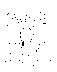
100851 First core
116 is shown having an embossed bottom and second core 118 is
shown having an embossed top. The embossed top of second core 118 and the
embossed
bottom of first core 116 provide increased longitudinal flow while reducing
lateral flow, and,
in this manner, reducing leakage. Said another way, the embossed top of second
core 118
and the embossed bottom of first core 116 allows fluid to move longitudinally
towards the
front and the back of a wearer, as opposed to towards the legs of a wearer.
CA 02905702 2015-09-11
WO 2014/149446
PCT/US2014/018500
100861 Each of the
first core 116 and the second core 118 may be composed of any
materials suitable for absorbing the fluids and discharge including, but not
limited to, a
fibrous material (e.g., fluffed wood pulp), a super absorbent polymer (SAP),
or the
combination of SAP and fibrous material. The SAP can be natural or synthetic
and may be
biodegradable. Non-limiting examples of SAP include polymers based on
acrylate(s) such as
sodium acrylate, potassium acrylate, and/or an alkyl acrylate(s) (e.g., methyl
acrylate, ethyl
acrylate, propyl acrylate, butyl acrylate, and hexyl acrylate). The absorbency
of the diaper
may vary depending upon whether it is intended for use by infants, children
and/or adults.
100871 While FIGS.
11 and 12 depict the first core 116 having an embossed bottom,
and the second core 118 having an embossed top (see also, for example, FIGS.
15 and 16), in
some embodiments, an absorbent article can have only a single core with no
embossing (see,
e.g., FIG. 13), a single core with embossing on both sides (see, e.g., FIG.
14), and/or other
combinations of one or two cores each with embossing on one, both, or neither
side. While
the FIGS. show absorbent articles include one or two cores, in some
embodiments, absorbent
articles can include more or fewer cores. While FIGS. 11, 12, 14, and 15
depict embossing as
including four spaced apart embossing "lines," in some embodiments, a core can
include
more or fewer embossing lines. In some embodiments, embossing lines can be
adjacent one
another, or can be a combination of adjacent and space apart embossing line.
In this manner,
the different combinations of embossing lines can define an embossing pattern.
While FIGS.
11, 12, 14, and 15 depict embossing substantially along the entire width and
length of each
respective core, in some embodiments a core can have embossing substantially
along an
entire width and/or length, and/or a portion of a width and/or length.
100881 FIG. 13 is a
cross-sectional view of a portion of an absorbent article 1000.
The absorbent articles described above generally consists of several layers
including an inner
layer 1001, an absorbent layer 1002, and an outer layer 1003, as depicted in
FIG. 10.In
26
CA 02905702 2015-09-11
WO 2014/149446
PCT/US2014/018500
general and applicable to any of the above embodiment, an absorbent layer 1002
may be
positioned between the inner layer 1001 and the outer layer 1003 of the
absorbent article.
The absorbent layer 1002 includes a core 1012. The core 1012 can be similar to
and include
similar characteristics with one or both of first core 116 and/or second core
118.
100891 The outer
layer 1003, which faces away from the wearer when the absorbent
article is secured to the wearer, is composed of a moisture-impervious fabric.
Accordingly,
the outer layer 1003 may be made of any material suitable to minimize or
prevent fluids and
other discharge from escaping the diaper. Non-limiting examples of suitable
materials for the
outer layer include polyethylene and/or breathable poly. According to some
embodiments,
the outer layer can be a thin film such as, for example, polyethylene film. As
will be
discussed in greater detail below, the outer layer is typically formed from a
plastic resin of
any of the above-referenced materials. This outer layer 1003 that prevents
diapers from
leaking also prevents air circulation, thus creating a warm, moist environment
where bacteria
and fungi can thrive. This bacteria and fungi can cause infectious diseases,
unpleasant odors,
urinary tract infections, bladder infections, kidney infections, diaper rashes
and the like.
100901 FIG. 14 is a
cross-sectional view of a portion of an absorbent article 1100.
The absorbent article 1100 can be similar to and include similar components
with the
absorbent article 1000. The absorbent article 1100 includes an inner layer
1101, an absorbent
layer 1102, and an outer layer 1103. In general and applicable to any of the
above
embodiment, an absorbent layer 1102 may be positioned between the inner layer
1101 and
the outer layer 1103 of the absorbent article. The absorbent layer 1102
includes a core 1112.
Unlike the absorbent article 1000, the core 1112 includes and embossed top
1112A and an
embossed bottom 1112B. In this manner, the core 1112 provides increased
longitudinal
movement of fluid on both the embossed top 1112A and embossed bottom 1112B of
the core
27
CA 02905702 2015-09-11
WO 2014/149446
PCT/US2014/018500
1012, and reduced lateral flow, decreasing the potential for leaks from the
side of the
absorbent article 1100.
100911 FIG. 12 is a
cross-sectional end view of a portion of an absorbent article 1200.
The absorbent article 1200 can be similar to and include similar components
with the
absorbent article 1000 and absorbent article 1100. The absorbent article 1200
includes an
inner layer 1201, an absorbent layer 1202, and an outer layer 1203. In general
and applicable
to any of the above embodiment, the absorbent layer 1202 may be positioned
between the
inner layer 1201 and the outer layer 1203 of the absorbent article. The
absorbent layer 1202
includes a first core 1212 and a second core 1214. Unlike the absorbent
article 1000, but
similar to absorbent article 100, the first core 1212 includes an embossed
bottom 1212A and
the second core 1214 includes an embossed top 1214A. In this manner, the first
core 1212
and the second core 1212B provide increased longitudinal movement of fluid on
both the
embossed top 1214A and embossed bottom 1212B of the second core 1112 and the
first core
1214, respectively.
100921 FIG. 16 is a
side view of absorbent article 1200. As depicted in FIG. 16 fluid
may flow from a wearer into contact with absorbent article 1200. Fluid flow is
shown in
FIG. 16 as dashed paths FF1, FF2, and FF3. While fluid flow is shown as dashed
paths in
FIG. 16, in some embodiments, fluid may not flow along a defined path, or
paths, in any
pattern, and may or may not contact absorbent article at any one or multiple
particular
locations. The fluid can first flow into contact with, be partially absorbed
by, and pass
through, inner layer 1201. The fluid can flow into contact with the embossed
top 1214A of
second core 1214. A portion of the fluid can be absorbed by second core 1214
and/or move
longitudinally and/or laterally on and/or within second core 1214; and a
portion of the fluid
can pass through second core 1214 and into contact with first core 1212. Both
the greater
surface area of the embossed top 1214 A, and the space created by embossed top
1214A
28
CA 02905702 2015-09-11
WO 2014/149446
PCT/US2014/018500
between inner layer 1201 can direct the fluid flow longitudinally towards the
front and the
back of the wearer, and away from edges of absorbent article 1200 (e.g.,
reduced lateral flow.
In this manner, when longitudinal flow is increased and/or when lateral flow
is decreased,
leakage can be reduced. A portion of the fluid can be absorbed by first core
1212 and/or
move longitudinally and/or laterally on and/or within first core 1212; and a
portion of the
fluid can pass through first core 1212 and into contact with outer layer 1203.
Both the greater
surface area of the embossed bottom 1212 A, and the space created by embossed
bottom
1212A between outer layer 1203 can direct the fluid flow longitudinally
towards the front and
the back of the wearer, and away from edges of absorbent article 1200 (e.g.,
reduced lateral
flow. In this manner, when longitudinal flow is increased and/or when lateral
flow is
decreased, leakage can be reduced.
100931 FIGS. 17-25
illustrate a securement portion, also referred to as a side panel,
1304 for connection with a chassis 1302, the securement portion 1304 including
a lamination
layer 1350 incorporated therein. Securement portion 1304 can be similar to and
include
similar components with side panel securement portions 104, 106, 108, 110.
Accordingly,
features of the side panel 1304 may be incorporated into either a back
securement portion or a
front securement portion or both. However, it will be readily apparent to one
of ordinary skill
in the art that a side panel consistent with the examples shown in FIGS. 17-25
is not limited
to the geometry of shown in these illustrative embodiments. Rather, one of
ordinary skill will
recognize that any of a broad variety of different side panel shapes, sizes
and geometries may
be appropriate.
100941 Lamination
layer 1350 may comprise a variety of different materials,
including a combination of materials, that may provide various benefits as
would be
recognized by one of ordinary skill in the art. For example, lamination layer
1350 may
comprise a high-loft nonwoven material to provide a softer side panel or an
absorbent
29
CA 02905702 2015-09-11
WO 2014/149446
PCT/US2014/018500
material to provide additional protection against leakage. Alternatively, the
lamination layer
may include one or more of the following materials: foam, airlaid, tissue,
pulp, SAP, coform
and meltblown material. In one embodiment, the lamination layer comprises a
polypropylene
or polyester nonwoven with a basis weight between 10 and 75 GSM, and more
preferably 48
GSM.
100951 In one
embodiment, as illustrated by FIGS. 17 and 20, the side panel 1304
comprises a first patient-facing layer 1354 and a second outwardly facing
layer 1352. A
lamination layer 1350 may be positioned between the first 1354 facing layer
and second 1352
facing layer. In a preferred embodiment, the lamination layer has a higher
loft than either the
patient-facing layer or outwardly facing layer. In addition, inclusion of the
lamination layer
1350 in the side panel 1304 and the resulting laminate structure allows the
use of materials
for the facing layers 1352, 1354 that may not otherwise be appropriate for use
without the
lamination layer, such as softer or more flexible materials. In one
embodiment, the facing
layers comprise, for example, 10 to 20 GSM SMS nonwoven materials. Other
appropriate
facing layer materials may include spunbond or spunlaced nonwoven materials
from
polypropylene or polyethylene.
100961 In the
embodiment shown in FIG. 17, the lamination layer 1350 has a
perimeter that is smaller than the perimeter of the first and second layers
such that a portion
1358 of the side panel 1304 without a lamination layer completely surrounds
the lamination
layer. Alternatively, in the embodiment shown in FIG. 18, the lamination layer
1350 extents
from a side panel top edge 1366 to a side panel bottom edge 1368 such that a
first portion
1370 without a lamination layer is formed adjacent the chassis 1302 and a
second portion
1372 without a lamination layer is formed adjacent the distal edge 1364 of the
side panel. In
a further embodiment, shown in FIGS. 21-22, alternating strips of lamination
layer 1380a,
1380b 1380c are positioned between panel layers 1352, 1354. These strips 1380
may extend
CA 02905702 2015-09-11
WO 2014/149446
PCT/US2014/018500
from panel top edge 1366 to panel bottom edge 1368. Alternatively, the strips
may extend
only part of the distance from top edge to bottom edge. If will be understood
by one of
ordinary skill in the art that, consistent with the present invention, the
lamination layer may
be arranged in any of a broad variety of continuous or intermittent layouts of
which the
embodiments discussed herein are only examples.
[0097] FIGS. 19-20
illustrate a further embodiment in which the side panel 1304
further incorporates an extension portion 1356 extending beyond the first and
second layers
1352, 1354. This extension portion 1356 may comprise a stretchable material,
such as an
elastic panel. The extension may be glued or bonded 1374 along the distal edge
1364 of the
side panel 1304. The extension may further comprise at least one fastener 1362
coupled
thereto. This fastener 1362 may be the hook portion of a hook-and-loop
fastener.
Alternatively, as shown in FIGS. 21-22, the side panel 1304 may include
fasteners 1320
similar to fasteners 120 as previously described with regard to FIG. 1.
[0098] As
illustrated by FIG. 20, the side panel 1304 may be glued or bonded
between an inner layer, or topsheet, 1330 and an outer layer, or backsheet,
1335 of the chassis
1302 in any manner that would be apparent to one of ordinary skill in the art.
[0099] The first
layer 1354, lamination layer 1350 and second layer 1352 may be
bonded by the use of glue, heat and pressure bonding, heat bonding alone,
pressure bonding
alone, or ultrasonic bonding methods. Bonding patterns can be created in a
continuous mode
or a patterned, registered manner. For example, FIG. 25 shows a side panel
1304 for
attachment to a chassis 1302 as illustrated in FIG. 17. The side panel
includes bonding
pattern 1382 that creates a quilted appearance and/or feel for the side panel.
The bonding
pattern may be created by bonding one or more of the layers at a number of
different bonding
sites 1384. Other bonding patterns may also be used. In addition, the edges of
the first and
second layers 1354, 1352 may be bonded or sealed along the periphery of the
side panel.
31
CA 02905702 2015-09-11
WO 2014/149446
PCT/US2014/018500
1001001 As
illustrated by FIGS. 23-34, additional bonding 1402 may be performed
after the time of laminating the lamination layer 1350 into the side panel
1304. This
additional bonding can improve the process of applying and folding the product
by virtue of
creating a "fold line" 1404 in the side panel. This can be made to improve
machine yield
through reduced scrap, reduced inefficiency and reduction in out of spec
products (folded
side panels).
1001011 In an
embodiment of the present invention, a skin care solution may be applied
to the lamination layer 1350. The skin care solution may be absorbed by the
lamination layer
and then released onto the wearer's skin over a period of time. The skin care
solution may be
a lotion, gel, or other solution that could provide benefits to the wearer's
skin, such as a
reduction in irritation or ulcers. The skin care solution may include one or
more ingredient
known to promote healthy skin or prevent skin breakdown. Examples of such
ingredients
may include, but are not limited to, aloe vera, alpha hydroxy acids (including
glycolic, lactic,
malic, citric and tartaric acids), soy, grapeseed extract, vitamins A, C and
E, coenzyme Q10,
flavanoids, polyphenols, oat flour, honey, lactic acid, shea butter,
petrolatum, lanolin,
petrolatum, cyclomethicone, dimethicone copolyol, glyceryl stearates and
propylene glycol
linoleate, silicone, mineral oil, beeswax, caprylic/capric triglycerides,
cyclomethicone,
hydrogenated castor oil, mineral oil, lanolin, petroleum, petrolatum,
silicone, dimethicone,
vegetable oils, or any other ingredient know to improve skin condition. In
further
embodiments, a skin care solution may be applied to other absorbent portions
of the
absorbent article. For example, a skin care solution could be applied to one
or more sections
of the first absorbent core portion 116 or second absorbent core portion 118.
[00102] As
illustrated in FIG. 26, a further embodiment of the invention that may
include a sacral lamination layer 1410 may be added to the inside surface 1404
of a rear
portion 1406 of the chassis 1302. The sacral lamination layer may be
positioned such that it
32
CA 02905702 2015-09-11
WO 2014/149446
PCT/US2014/018500
is positioned adjacent a users sacral region, in vicinity of the intergluteal
cleft and the
tailbone, when wearing the absorbent article. This lamination layer 1410 may
overlap with
one or more other components that make up the chassis 1302, such as the first
core portion
116. The sacral lamination layer may include a high-loft material that is
affixed to the
chassis topsheet 1330, by adhesive or other bonding means know to one of skill
in the art. A
further embodiment may include a patient facing layer positioned over the
sacral lamination
layer. The high-loft material and patient facing layer may be similar to those
described above
for use in side panel 1304. A skin care solution, such as described above, may
be applied to
the sacral lamination layer 1410.
1001031 The sacral
lamination layer 1410 may have a variety of different shapes,
including rectangular, oval, or "butterfly" shaped. In addition, the sacral
lamination layer or
sacral lamination layer and patient facing layer may include one or more of a
variety of
different embossing shapes or patterns as described herein or as would be
known to one
skilled in the art. Embodiments of the invention contemplate absorbent
articles using both a
lamination layer 1350 in side panel 1304 and a sacral lamination layer 1410.
Alternatively
side panel lamination layer or sacral lamination layer may be used
independently.
1001041 FIGS. 27-29
illustrate embodiments of a method for manufacturing an
absorbent article with a rear side panel 1304 in accordance with embodiments
shown in
FIGS. 17-25. Embodiments of the manufacturing method may include the following
steps:
(1) Unwind a continuous web 1502 first facing layer 1354 of a side panel 1304
from a roll
1506 of facing material in a direction indicated by arrow 1508. (2) Unwind a
continuous web
1500 of first lamination layer 1350 for the side panel from a roll 1504 of
facing material in a
direction indicated by arrow 1510. (3) Provide a short piece 1512 of
lamination layer by
feeding the lamination layer through a slip and cut 1514 (also known to those
of skill in the
art as cut and place) can also be performed with a cutting unit followed by a
placing unit ¨ as
33
CA 02905702 2015-09-11
WO 2014/149446
PCT/US2014/018500
driven by either mechanical cam or servo motor unit, thereby providing an
intermittent patch
1512 of lamination layer 1350 onto a continuous web of the first facing layer
1354 of the side
panel 1304. This process may require adhesive 1516 to be applied to the first
facing layer
1502. The slip/cut applicator may also require vacuum in order to hold the
lamination layer
within the unit until severed, accelerated and glued in place to the first
facing layer. (4)
Apply skin care lotion 1520 to the lamination layer piece 1512 through
intermittent
application using a spray applicator 1518, extrusion die, rotary gravure
printing, or other
applicator process. (5) Unwind a continuous web 1522 of second facing layer
1352 of side
panel material from a roll 1524 of facing material in a direction indicated by
arrow 1526. (6)
Marry the first facing layer 1502 (with intermittent lamination layer patches
1512) with the
second facing layer 1522. (7) Feed the combined layers through an ultrasonic
bonding unit
1528, or a heated calendaring unit (also known as heat and pressure bonding
unit), including
a pattern roll 1530, to provide a quilted lamination pattern 1382 (or other,
aesthetically
pleasing pattern) which traps the lamination layer between the facing layers
and provides an
appearance of softness. (Hotmelt adhesive lamination can also be utilized for
this
application, but without benefit of a quilted bonding appearance) (8) Using
the same pattern
roll 1530, or a second means (which could be another ultrasonic bonding unit
or a pressure
unit, or a heated unit), provide a bonding pattern 1402 on the edges of the
side panel 1304.
(9) Add tape tabs 120 to the panel assemblies (not shown). An alternative to
tape tabs as
shown would be a continuous hook, a hook strip 1362 that is shorter than the
panel assembly,
or a plurality of hook strips that can be used to preferentially attach the
side panel 1304 to
either a corresponding side panel, or the front of the product's chassis 1302.
Embodiments of
the portion of the manufacturing process shown in FIG. 27 create a continuous
panel web
1532.
34
CA 02905702 2015-09-11
WO 2014/149446
PCT/US2014/018500
[00105] FIG. 28
illustrates an embodiment of a further portion of the manufacturing
process, including the following steps: (10) Provide a first continuous panel
web 1532a and a
second continuous panel web 1532b. The two panel webs 1532a, 1532b are
overlapped in a
slightly offset manner 1534. (11) A cutoff and spacing unit 1536 severs and
spaces the panel
webs into discrete pairs 1538 of side panels 1304.
[00106] As
illustrated in FIG. 29, an embodiment of a further portion of the
manufacturing process includes the following steps: (12) Place the discrete
pairs 1538 of side
panels 1304 onto a continuous web 1540 of topsheet 1330 material. (13) Fold an
edge of
each side panel 1304 under the topsheet web 1540 along fold line 1404 as shown
by arrows
1542. (14) Marry a continuous web 1544 of backsheet 1335 material, combined
with
absorbent cores, to the continuous web 1540 or the topsheet. (15) Adhere an
edge of each
side panel 1304 between the topsheet 1330 and the backsheet 1335, as
illustrated in FIG. 20.
In an alternate embodiment of this process, further side panels are
manufactured without the
tape tabs for use in a front side panel application.
[00107] While the
present invention has been described with reference to one or more
particular embodiments, those skilled in the art will recognize that many
changes may be
made thereto without departing from the spirit and scope of the present
invention.
Furthermore, components from one embodiment can be used in other non-exclusive
embodiments. By way of example, any of the absorbent articles described herein
can include
any of the absorbent layers described in FIGS. 10-12. Each of these
embodiments and
obvious variations thereof is contemplated as falling within the spirit and
scope of the
invention, which is set forth in the following alternative embodiments.