Note: Descriptions are shown in the official language in which they were submitted.
CA 02905938 2015-09-11
WO 2014/151415 PCT/US2014/025685
ACOUSTIC LINE TRACING SYSTEM AND
METHOD FOR FLUID TRANSFER SYSTEM
FIELD OF THE INVENTION
The present invention relates to a system and method for tracing a
particular tubing set from end to end, more particularly to a system and
method that uses
acoustic vibration to trace a tubing system for fluid transfer, and even more
particularly to
a system and method for tracing tubing systems used in the medical industry
for transfer
of fluids, such as intravenous infusion tubing, using acoustic vibration.
BACKGROUND
Errors in administration of medication through a fluid transfer system,
such as a patient infusion system or an automatic compounder, can result from
many
causes, including misconnections. Accordingly, to reduce the potential for
such errors,
professional guidelines and/or standard operating procedures require
clinicians, such as
nurses and pharmacists, to perform "line management," also known as line
tracing,
numerous times throughout their working shifts. In the case of an automatic
compounder,
line management involves verifying each medication source container is routed
through
tubing to the correct input of the mixing manifold and pump. In the case of a
patient
infusion system, line management involves verifying that each medication
source
container, typically a bag, bottle, or syringe, is routed through tubing to
the correct
catheter, and that the tubing is associated with the correct pump channel (if
an infusion
pump is used). The activity further includes verifying that it is safe to join
two or more
tubing segments containing different medications and/or flowing at different
rates. By
way of example, a nurse or other clinician may perform line management for
each patient
when starting a shift, when receiving a patient from another facility, another
area of the
hospital, or a different clinician, and just prior to administration of an
intravenous
medication. Repeated performance of the detailed line management procedure
imposes a
time burden on the clinicians, and is prone to errors, particularly as the
complexity of a
patient's overall infusion tubing system increases. That is, multiple tubing
sets,
medications, junctions, access ports, pump channels, and catheters increase
the amount of
time required to perform line management and also introduce additional
opportunities for
error in line management.
1
CA 02905938 2015-09-11
WO 2014/151415 PCT/US2014/025685
To facilitate line management, clinicians often manually label infusion
setups at various locations throughout the tubing system. Generally, the
labeling is crude,
using materials on hand such as medical tape wrapped around the tubing and
labeled with
identifying information such as the medication name. This labeling is repeated
at several
points throughout the system. For example, labels may be placed at the spike
end of a
tubing set, at the catheter connection, at each access port and junction, on
the roller clamp
and slide clamp, on the catheter, on the pump channel itself, and on the
medication
container. When applying such labels, a clinician manually slides his or her
hand along
the tube, progressing from a first tube end to a second tube end, and labeling
desired
points along the length of the tube.
Line management systems should be capable of identifying the correct
line, catheter, and connector prior to connecting any new medicine container
and line or
prior to injecting a medication into an existing access port. Additionally,
the system
should allow a user to correctly identify a container and its corresponding
line and pump
interface before loading the tubing line into the pump. The system should also
maintain
clear physical and visual association among the container, line, pump, and
catheter.
Proposed systems for facilitating the line management process include color
coding of the
tubing sets used in the infusion system, use of the tubing as an optical
waveguide similar
to glass or plastic optical fibers, and use of electrically conducting wires
embedded in the
wall of the tubing. Each of these solutions provides some advantages, but a
primary
disadvantage to each proposal is that it would require development of a
specialized tubing
set.
Accordingly, there is a need for a system that facilitates accurate line
management without the need for development of new tubing systems.
SUMMARY
An improved acoustic line tracing system addresses these needs. The
acoustic sensor system allows for accurate tracing of a line, without the need
for
developing a specialized tubing set. Accordingly, existing tubing sets, with
known
physical characteristics can be used with the acoustic tracing system.
In a first aspect, an acoustic line tracing system for tracing a fluid
transfer
system tubing line includes an acoustic receiver operably connectable to the
tubing line
and configured to receive a vibratory signal. The acoustic receiver includes a
vibration
sensor disposed to contact the tubing line and configured for detecting
vibration of the
2
CA 02905938 2015-09-11
WO 2014/151415 PCT/US2014/025685
surface of the tubing line caused by the vibratory signal, and an indicator
producing at
least one of an audio and a visual cue when the vibration sensor detects the
vibratory
signal.
In another aspect of the invention, an acoustic line tracing system for
verifying continuity of a tubing set in an infusion system includes a first
acoustic receiver
connectable to the tubing line and configured for receiving a vibratory
signal. The first
acoustic receiver has a vibration sensor disposed to contact the tubing line
and configured
for detecting vibration of the surface of the tubing line caused by the
vibratory signal. A
signal transmitter operatively contacts the tubing set and is electrically
coupled with the
first acoustic receiver. The signal transmitter is configured for generating
acoustic
vibrations in the tubing line when the sensor detects a vibratory signal. A
second acoustic
receiver is connectable to the tubing line and configured for receiving the
acoustic
vibrations generated by said signal transmitter. The second acoustic receiver
includes a
sensor disposed to contact the tubing line and configured for detecting
vibrations in the
surface of the tubing line caused by the acoustic vibrations, and an indicator
producing at
least one of an audio and a visual cue when the vibration sensor detects the
vibrations.
The first acoustic receiver and the signal transmitter are separated by at
least one
vibration dampening component.
In still another aspect of the invention, a method for tracing a tubing set to
determine set continuity includes a step of providing an acoustic receiver in
contact with
the tubing set at a first position along the tubing set. The acoustic receiver
has a vibration
sensor operatively that is in contact with the tubing set and capable of
sensing vibrations
in the tubing set, and an indicator capable of producing at least one of an
audio and a
visual cue when said vibration sensor detects the vibrations. The method
further includes
a step of inducing a vibratory signal at a second position along the tubing
set, and a step
of detecting, using the provided acoustic receiver, whether or not the
vibratory signal is
received at the first position along the tubing set. The method also includes
a step of
determining whether the tubing set is continuous between the first position
and the second
position, where the tubing set is determined to be continuous if the vibration
sensor
detects the vibratory signal at the detecting step. The indicator produces the
audio and/or
visual cue when it is determined that the tubing set is continuous.
3
CA 02905938 2015-09-11
WO 2014/151415 PCT/US2014/025685
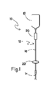
BRIEF DESCRIPTION OF THE DRAWINGS
FIGURE 1 shows an infusion system including a removable acoustic
receiver according to an embodiment of the present invention;
FIG. 2 shows an infusion system including an infusion pump and a
removable acoustic receiver according to an embodiment of the present
invention;
FIG. 3 shows a schematic drawing of an acoustic receiver as shown in
FIGs. 1 and 2;
FIG. 4 shows a graph of a vibratory acoustic signal received by the
acoustic receiver of FIG. 3; and
FIG 5 shows the infusion system of FIG. 2, and a removable acoustic line
receiver including a relay.
DETAILED DESCRIPTION
Referring now to FIGs. 1 and 2, a fluid transfer system is shown
schematically as infusion system 10. While FIGs. 1 and 2 show the fluid
transfer system
as patient infusion system 10, those of skill in the art will recognize that
other fluid
transfer systems, such as automatic compounder systems, are within the scope
of the
present invention. The infusion system 10 includes a medication container 12,
a catheter
14 for connection to a patient, and a tubing set 16 providing fluid
communication
between the medication container 12 and the catheter 14. The infusion system
10 can be
a so-called "gravity-fed" pumpless system as shown in FIG. 1, or optionally
includes an
infusion pump 18 for pumping the medication from the container 12 through the
tubing
set 16 and catheter 14 into a patient as shown in FIG. 2. While the systems 10
shown in
FIGs. 1 and 2 include equipment for delivering a single medication for
clarity, those of
skill in the art will recognize that an infusion system may include multiple
containers,
catheters, pumps, and tubing sets.
The medication container 12 can be, for example, a bag, bottle, syringe, or
other standard container used to contain liquid medications. There is no
particular
restriction regarding what containers may be used. A drip chamber 20 is
preferably
disposed directly downstream from the medication container 12. The drip
chamber 20
allows gas to separate from fluid exiting the medication container 12, thus
helping to
prevent an air embolism, and also helps a clinician estimate the flow rate of
the
medication by allowing the clinician to count the number of drops of the
medication that
enter the drip chamber 20 in a given period of time.
4
CA 02905938 2015-09-11
WO 2014/151415 PCT/US2014/025685
The catheter 14 can be any standard equipment for use with a patient. The
catheter 14 may be, for example, a temporary catheter inserted into a
peripheral vein, a
peripherally inserted central catheter, a central venous catheter, or other
catheter known to
those in the art. Likewise, the tubing set 16 is any standard tubing set used
to connect the
medication container 12 to the catheter 14.
As shown in FIG. 2, the infusion pump 18 is any known pump used to
administer fluid intravenously. The pump 18 is used to help regulate fluid
flow through
the system 10, and may be used to vary an infusion rate based on, for example
time
and/or patient demand. The pump 18 is positioned between the drip chamber 20
and the
catheter 14, and may include one or more "channels," with each channel used to
regulate
fluid flow from a distinct medication container through a distinct tubing set.
FIGs. 1 and 2 each show at least one acoustic receiver 22 connected to an
exterior surface of the tubing set 16. The acoustic receiver 22 is a device
capable of
detecting acoustic waves transmitted through the tubing set 16. The receiver
22 is
preferably removably secured to the tubing set 16, such that a clinician can
position the
receiver at any desired position along the length of the tubing set, and can
move the
receiver from one tubing set to another as desired. While FIG. 2 shows the
acoustic
receiver 22 as a separate device, artisans will recognize that the receiver
can optionally be
incorporated into the pump 18 as an integrated acoustic receiver disposed at
one or both
of the upstream and downstream sides of the pump without departing from the
scope of
the invention. Alternatively, the receiver 22 is optionally formed as an
integral portion of
the tubing set 16, disposed near the medication container 12 and/or near the
catheter 14.
Alternatively, the receiver 22 is optionally formed as an integral portion of
the infusion
system 10, including the medication container 12 and/or the catheter 14.
As shown in FIG. 3, the acoustic receiver 22 includes a sensor 24, an
indicator 26, and a power source 28. The sensor 24, such as a vibration sensor
is disposed
in contact with the tubing set 16, and is used to detect an acoustic vibratory
signal
transmitted through the tubing set 16. In the preferred embodiment, the sensor
24 is a
transducer capable of converting vibrations from the tubing set 16 into an
electrical
signal. For example, the sensor 24 is optionally a microphone such as a
contact
microphone or other piezoelectric device.
The sensor 24 is electrically connected to the indicator 26, which provides
at least one of an audio and a visual or other indication when the sensor 24
detects sound
waves. The indicator 26 is preferably a small indicator light such as a light
emitting
5
CA 02905938 2015-09-11
WO 2014/151415 PCT/US2014/025685
diode, a small loudspeaker capable of emitting an audible tone, or other
device capable of
providing an observable signal to a clinician.
The power source 28 provides power to the receiver 22. The power source
28 is preferably a compact portable power source such as a battery. However,
other
sources, such as a connection to mains power, photovoltaic panels, and the
like may be
used without departing from the scope of the invention.
The receiver 22 is preferably removably connected to the tubing itself
and/or any component of the tubing set 16, such as the drip chamber 20 and/or
access
ports. Alternatively, the receiver 22 can be connected to other portions of
the infusion
system 10, including the medication container 12 or the catheter 14. This
connection is
formed by, for example a spring-biased clamp. The force exerted on the tubing
set 16 by
the receiver 22 is desirably sufficient for maintaining steady contact between
the sensor
24 and the tubing set, so that an accurate reading can be performed. However,
the biasing
force retaining the receiver 22 in place should not be so strong as to occlude
the tubing set
16.
Turning now to FIG.5, the signal sensed by the acoustic receiver 22 is
preferably provided, for example, by a signal transmitter 30 preferably
removably
connected to the tubing set. The transmitter 30 may be any device capable of
producing a
vibratory acoustic signal, preferably an ultrasound signal having a frequency
greater than
20 kHz. In the preferred embodiment, the transmitter 30 includes a
piezoelectric device
configured for generating ultrasonic acoustic vibrations. The transmitter 30
can be a
separate device, or optionally can be incorporated into the tubing set 16.
Alternatively,
the transmitter 30 can optionally be attached to or formed integrally with
other elements
of the infusion system 10, including the medication container 12 and/or the
catheter 14.
As shown in FIG. 5, the transmitter 30 can also optionally be incorporated
into the
infusion pump 18 as an integrated signal transmitter 18a. While FIG. 5 shows
integrated
signal transmitter 18a disposed on the downstream side of the pump 18, those
of skill in
the art will recognize that an integrated signal transmitter can be disposed
at one or both
of the upstream and downstream sides without departing from the scope of the
invention.
Alternatively, a pumping mechanism of the infusion pump 18 can be the signal
transmitter 30. While in the depicted embodiment, the signal transmitter 30 is
separate
from the acoustic receiver 22, it is also contemplated that the acoustic
receiver 22 is also
optionally capable of generating an acoustic vibratory signal, thus operating
as a signal
transmitter/receiver or "transceiver". As a further alternative, the vibratory
signal may be
6
CA 02905938 2015-09-11
WO 2014/151415 PCT/US2014/025685
generated manually, for example by a clinician tapping the tubing set using,
for example,
a finger or other implement. The vibratory acoustic signal is preferably
applied at a
location 13 distant from the receiver 22, so that opposite ends of the tubing
set 16 are
determined to be continuous. As examples, FIG. 1 shows the vibratory signal
can be
applied to the tubing set 16 at the location 13 disposed proximate to the
medication
container 12, while the receiver 22 is positioned proximate to the catheter
14; FIG. 2
shows the vibratory signal applied at a location 13 downstream from the pump
18, with
the receiver 22 positioned near the catheter 14; and FIG 5 shows the vibratory
signal
applied at the position 13 near the medication bag, with a first receiver 22
positioned
upstream of the pump 18.
In practice, to aid in creation of an infusion mapping, a vibratory signal is
provided at a first end of the tubing set 16. The signal is optionally
provided
continuously or intermittently (e.g., a pulsed signal). The acoustic receiver
22 is then
systematically connected to each of a plurality of candidate tubes at a second
end of the
infusion system 10, until the vibratory signal is detected by the sensor 24 at
the tube
which is in fluid communication with the tube coupled to the signal
transmitter. FIG. 4
shows a graph indicating receipt of a pulsed signal by the sensor 24, such as
by the signal
transmitter 30 or by a clinician tapping on the tubing set 16. In response to
the sensor 24
receiving the vibratory signal, the indicator 26 provides an indication to the
clinician that
the signal has been received. The clinician then knows that the tubing section
16 to
which the acoustic receiver 22 is connected is continuous with the tubing
section to which
the vibratory signal is provided.
Referring now to FIG. 2, addition of the infusion pump 18 to the system 10
creates additional complications for acoustic continuity sensing. In
particular, the
infusion pump 18 may dampen the provided vibratory signal sufficiently that a
signal
provided on an upstream side of the pump cannot be accurately detected on a
downstream
side of the pump (or vice versa). One method of accommodating the dampening
factor of
the infusion pump 18 is to use a two-step process, whereby the receiver 22 is
initially
placed on the tubing set 16 near the catheter 14, and a vibratory signal is
systematically
transmitted from the location 13 associated with each pump channel output on
the
downstream side of the pump or pumps (if there are multiple pumps in the
infusion
system), one by one, until continuity is established on the downstream side of
the infusion
system. This allows the clinician to determine which pump channel is
associated with the
tubing set 16 near the catheter 14. Then, a vibratory signal is transmitted
from the
7
CA 02905938 2015-09-11
WO 2014/151415 PCT/US2014/025685
location 13 associated with the upstream side of the pump 18 on the same
channel, and
the receiver 22 is systematically moved from one tubing system to another near
the
medication containers 12 until the signal is received. This shows continuity
from the
medicine container 12 to the pump 18. In this way, continuity can be
established fully
from the medication container 12 to catheter 14 using only a single receiver
22 and a
single transmitter 30, even with an intervening infusion pump 18. This is
generally
referred to as a "pump out" approach because the signals are transmitted from
positions
proximal to the pump in both upstream and downstream directions. The system
and
method can be streamlined when the upstream and downstream signal transmitters
30 and
associated software are incorporated into the pump 18. In this case, only a
single receiver
22 needs to be positioned by the clinician.
One of skill in the art will note that the above-listed steps are optionally
performed in the opposite order, such that continuity from the medication
container 12 to
the pump 18 is determined before continuity from the pump to the catheter 14,
without
departing from the scope of the invention. Further, artisans will appreciate
that the
positions of the transmitter 30 and receiver 22 could be switched to generate
a "pump in"
workflow, such that signals are transmitted from the catheter 14 and the
medication
container 12, and received at the upstream and downstream sides of the pump
18. The
system and method can be streamlined when the upstream and downstream acoustic
receivers 22 and associated software are incorporated into the pump 18. In
this case, only
a single signal transmitter 30 needs to be positioned by the clinician.
Further
simplification is possible when finger taps are used in place of the signal
transmitter 30.
Similarly, a "top down" workflow uses a signal transmitted from the
medicine container and received at the pump upstream side, and a signal
transmitted from
the pump downstream side and received at the catheter. A "bottom up" workflow
uses a
signal transmitted from the catheter and received at the pump downstream side
and a
signal transmitted from the pump upstream side and received at the medicine
container.
The chart below shows the positioning of the transmitters and receivers with
respect to
the medication container, pump upstream side, pump downstream side, and
catheter:
8
CA 02905938 2015-09-11
WO 2014/151415 PCT/US2014/025685
Medication Pump Pump Catheter
Container Upstream Side Downstream
Side
"pump out" Receiver Transmitter Transmitter Receiver
"pump in" Transmitter Receiver Receiver Transmitter
"top down" Transmitter Receiver Transmitter Receiver
"bottom up" Receiver Transmitter Receiver Transmitter
While each of the above configurations and workflows results in the same
determination of continuity, different clinicians may find certain workflows
more
expedient and/or more intuitive. Accordingly, a system that allows for the
flexibility to
determine continuity in whichever way a clinician prefers is advantageous in
that it
encourages the clinicians to use the equipment, reducing the propensity for
errors in line
tracing and increasing the speed at which a line tracing can be performed.
Another method of accommodating the dampening factor of the infusion
pump 18 is to use a relay 32. As shown in FIG. 5, the infusion system 10
optionally
includes a relay 32 having the acoustic receiver 22 electrically coupled to
the signal
transmitter 30 via a wired or wireless connection. The relay is disposed such
that the
receiver and the transmitter are on opposite sides of the pump (i.e., the
receiver 22 is
disposed upstream, while the transmitter 30 is disposed downstream, or vice
versa).
Then, an acoustic signal is provided to the tubing set 16 on the side of the
pump that
includes the receiver. When the receiver 22 receives the provided signal, a
corresponding
signal is generated by the electrically coupled signal transmitter 30. Thus,
the dampening
effect of the pump 18 is negated.
It is also contemplated that the signal receiver 22 and the signal transmitter
30 may communicate with one another, either wirelessly or via wired
connection. In
particular, the transmitter 30 preferably transmits information regarding one
or more
characteristics of the transmitted acoustic vibration to the receiver 22.
Such
characteristics preferably include one or more of signal frequency (or range
of
frequencies), signal amplitude (or range of amplitudes), signal timing, a
particular signal
pattern to be transmitted, or other characteristics identifying the signal.
This allows the
receiver 22 to discriminate between a received signal from the transmitter 30
and noise or
other extraneous vibrations in the tubing caused by, for example cross-talk
between
9
CA 02905938 2015-09-11
WO 2014/151415 PCT/US2014/025685
numerous transmitters and receivers in a complex infusion system, incidental
contact
between multiple tubes of an infusion system, vibrations induced by a pump 18,
or other
sources of vibration present within system 10. The receiver 22 compares the
signal
received at the sensor 24 with the one or more signal characteristics and, if
the received
signal matches the characteristics, indicates that the signal is received via
the indicator 26.
While the principles of the present infusion set line tracing system have
been described above in connection with specific apparatus and applications,
it is to be
understood that this description is made only by way of example and not as a
limitation
on the scope of the claims following below.