Note: Descriptions are shown in the official language in which they were submitted.
CA 02906548 2015-09-14
WO 2014/160472 PCT/US2014/026753
CHARACTERISTIC-BASED COMMUNICATIONS
FIELD
Embodiments of the invention relate generally to electrical and electronic
hardware,
computer software, wired and wireless network communications, wearable, hand
held, and
portable computing devices for facilitating communication of information. More
specifically,
disclosed are an ecosystem of wirelessly interconnected media devices that may
re-configure
themselves based on content to be handled by the media devices and the number
of media
devices present.
BACKGROUND
Conventional paradigms for media devices that wirelessly connect with and
communicate
with each other and/or a user device (e.g., a tablet or smartphone) typically
require the user to
configure each media device added to the users system of media devices. For
example,
Bluetooth0 (BT) devices require the user to place the media device in BT
pairing mode and the
user device in BT discovery mode. When the user device detects the BT radio of
the media
device, the two devices may "pair" with each other. Sometimes, a code must be
entered before
pairing may occur. After the devices are paired they may wirelessly
communicate with each
other and depending on the BT protocols, exchange data and control. Typically,
when the user
adds another BT device, the pairing between the user device and the prior BT
device must be
broken and the user must pair his/her device with the newly added BT device.
For media
devices that use other forms of wireless communications, such as WiFi, the
process of adding
and configuring devices may be more complicated. The user usually has to
configure each new
media device with information about the wireless network the device will
communicate with,
such as wireless network name, password, etc. Each wireless device added to
the users system
may be aware of the wireless network and other entities that are connected
with the network;
however, many of those devices may not be configured to work well with one
another without
effort on part of the user to make inter-operability possible. Furthermore, as
devices are added to
a user's system the roles each device servers in the system may also need to
change. Further, in
some instances, the role a device servers in a system may need to change based
on the content
the device is to act on, such as audio, video, phone calls, etc. However, if
these wirelessly
enabled devices are not designed to work well with one another, then as
devices are added to or
1
CA 02906548 2015-09-14
WO 2014/160472 PCT/US2014/026753
removed from the system, the user is left with the task of configuring the
devices to serve new
roles.
Ideally, each media device may sense its surrounding environment and other
media
devices, and based on content, act to re-configure itself to serve a different
role for the user until
the circumstances change and the media device reverts back to its prior role
or switches to yet
another new role.
Thus, what is needed are devices, methods, and software that allow a media
device to
sense its environment, content to be processed, and user preferences to re-
task the role it servers
for the user on a dynamic basis.
BRIEF DESCRIPTION OF THE DRAWINGS
Various embodiments or examples ("examples") of the invention are disclosed in
the
following detailed description and the accompanying drawings. The drawings are
not
necessarily to scale:
FIG. 1 depicts a block diagram of a media device according to an embodiment of
the
present application;
FIG. 2A depicts one example of a first pairing and configuration scenario for
a user
device and a media device according to an embodiment of the present
application;
FIG. 2B depicts example scenarios for another media device being configured
using a
configuration from a previously configured media device according to an
embodiment of the
present application;
FIG. 3 depicts one example of a flow diagram of a process for installing an
application on
a user device and configuring a first media device using the application
according to an
embodiment of the present application;
FIGS. 4A and 4B depict example flow diagrams for processes for configuring an
un-
configured media device according to embodiments of the present application;
FIGS. 5A through 5D depict block diagrams of media devices that configure
themselves
based on characteristics that may be derived from a variety of inputs, data,
configurations, or
other information available to the media device according to an embodiment of
the present
application;
FIGS. 6A through 6E depict block diagrams of an ecosystem of media devices
that re-
configure themselves to perform different roles according to an embodiment of
the present
application; and
2
CA 02906548 2015-09-14
WO 2014/160472 PCT/US2014/026753
FIGS. 7A and 7B depict block diagrams of media devices in an ecosystem that
use sensor
inputs to re-configure roles a media device serves according to an embodiment
of the present
application.
DETAILED DESCRIPTION
Various embodiments or examples may be implemented in numerous ways, including
as
a system, a process, an apparatus, a user interface, or a series of program
instructions on a non-
transitory computer readable medium such as a computer readable storage medium
or a
computer network where the program instructions are sent over optical,
electronic, or wireless
communication links. In general, operations of disclosed processes may be
performed in an
arbitrary order, unless otherwise provided in the claims.
A detailed description of one or more examples is provided below along with
accompanying figures. The detailed description is provided in connection with
such examples,
but is not limited to any particular example. The scope is limited only by the
claims and
numerous alternatives, modifications, and equivalents are encompassed.
Numerous specific
details are set forth in the following description in order to provide a
thorough understanding.
These details are provided for the purpose of example and the described
techniques may be
practiced according to the claims without some or all of these specific
details. For clarity,
technical material that is known in the technical fields related to the
examples has not been
described in detail to avoid unnecessarily obscuring the description.
FIG. 1 depicts a block diagram of one embodiment of a media device 100 having
systems
including but not limited to a controller 101, a data storage (DS) system 103,
a input/output (I/0)
system 105, a radio frequency (RF) system 107, an audio/video (A/V) system
109, a power
system 111, and a proximity sensing (PROX) system 113. A bus 110 enables
electrical
communication between the controller 101, DS system 103, I/O system 105, RF
system 107, AV
system 109, power system 111, and PROX system 113. Power bus 112 supplies
electrical power
from power system 111 to the controller 101, DS system 103, I/0 system 105, RF
system 107,
AV system 109, and PROX system 113.
Power system 111 may include a power source internal to the media device 100
such as a
battery (e.g., AAA or AA batteries) or a rechargeable battery (e.g., such as a
lithium ion or nickel
metal hydride type battery, etc.) denoted as BAT 135. Power system 111 may be
electrically
coupled with a port 114 for connecting an external power source (not shown)
such as a power
supply that connects with an external AC or DC power source. Examples include
but are not
3
CA 02906548 2015-09-14
WO 2014/160472 PCT/US2014/026753
limited to a wall wart type of power supply that converts AC power to DC power
or AC power to
AC power at a different voltage level. In other examples, port 114 may be a
connector (e.g., an
IEC connector) for a power cord that plugs into an AC outlet or other type of
connecter, such as
a universal serial bus (USB) connector. Power system 111 provides DC power for
the various
systems of media device 100. Power system 111 may convert AC or DC power into
a form
usable by the various systems of media device 100. Power system 111 may
provide the same or
different voltages to the various systems of media device 100. In applications
where a
rechargeable battery is used for BAT 135, the external power source may be
used to power the
power system 111, recharge BAT 135, or both. Further, power system 111 on its
own or under
control or controller 101 may be configured for power management to reduce
power
consumption of media device 100, by for example, reducing or disconnecting
power from one or
more of the systems in media device 100 when those systems are not in use or
are placed in a
standby or idle mode. Power system 111 may also be configured to monitor power
usage of the
various systems in media device 100 and to report that usage to other systems
in media device
100 and/or to other devices (e.g., including other media devices 100) using
one or more of the
I/O system 105, RF system 107, and AV system 109, for example. Operation and
control of the
various functions of power system 111 may be externally controlled by other
devices (e.g.,
including other media devices 100).
Controller 101 controls operation of media device 100 and may include a non-
transitory
computer readable medium, such as executable program code to enable control
and operation of
the various systems of media device 100. DS 103 may be used to store
executable code used by
controller 101 in one or more data storage mediums such as ROM, RAM, SRAM,
RAM, SSD,
Flash, etc., for example. Controller 101 may include but is not limited to one
or more of a
microprocessor (03), a microcontroller (03), a digital signal processor (DSP),
a baseband
processor, an application specific integrated circuit (ASIC), just to name a
few. Processors used
for controller 101 may include a single core or multiple cores (e.g., dual
core, quad core, etc.).
Port 116 may be used to electrically couple controller 101 to an external
device (not shown).
DS system 103 may include but is not limited to non-volatile memory (e.g.,
Flash
memory), SRAM, DRAM, ROM, SSD, just to name a few. In that the media device
100 in some
applications is designed to be compact, portable, or to have a small size
footprint, memory in DS
103 will typically be solid state memory (e.g., no moving or rotating
components); however, in
some application a hard disk drive (HDD) or hybrid HDD may be used for all or
some of the
4
CA 02906548 2015-09-14
WO 2014/160472 PCT/US2014/026753
memory in DS 103. In some examples, DS 103 may be electrically coupled with a
port 128 for
connecting an external memory source (e.g., USB Flash drive, SD, SDHC, SDXC,
microSD,
Memory Stick, CF, SSD, etc.). Port 128 may be a USB or mini USB port for a
Flash drive or a
card slot for a Flash memory card. In some examples as will be explained in
greater detail
below, DS 103 includes data storage for configuration data, denoted as CFG
125, used by
controller 101 to control operation of media device 100 and its various
systems. DS 103 may
include memory designate for use by other systems in media device 100 (e.g.,
MAC addresses
for WiFi 130, network passwords, data for settings and parameters for A/V 109,
and other data
for operation and/or control of media device 100, etc.). DS 103 may also store
data used as an
operating system (OS) for controller 101. If controller 101 includes a DSP,
then DS 103 may
store data, algorithms, program code, an OS, etc. for use by the DSP, for
example. In some
examples, one or more systems in media device 100 may include their own data
storage systems.
I/O system 105 may be used to control input and output operations between the
various
systems of media device 100 via bus 110 and between systems external to media
device 100 via
port 118. Port 118 may be a connector (e.g., USB, HDMI, Ethernet, fiber optic,
Toslink,
Firewire, IEEE 1394, or other) or a hard wired (e.g., captive) connection that
facilitates coupling
I/O system 105 with external systems. In some examples port 118 may include
one or more
switches, buttons, or the like, used to control functions of the media device
100 such as a power
switch, a standby power mode switch, a button for wireless pairing, an audio
muting button, an
audio volume control, an audio mute button, a button for
connecting/disconnecting from a WiFi
network, an infrared (IR) transceiver, just to name a few. I/O system 105 may
also control
indicator lights, audible signals, or the like (not shown) that give status
information about the
media device 100, such as a light to indicate the media device 100 is powered
up, a light to
indicate the media device 100 is in wireless communication (e.g., WiFi,
Bluetooth0, WiMAX,
cellular, etc.), a light to indicate the media device 100 is Bluetooth0
paired, in Bluetooth0
pairing mode, Bluetooth0 communication is enabled, a light to indicate the
audio and/or
microphone is muted, just to name a few. Audible signals may be generated by
the I/O system
105 or via the AV system 107 to indicate status, etc. of the media device 100.
Audible signals
may be used to announce Bluetooth0 status, powering up or down the media
device 100, muting
the audio or microphone, an incoming phone call, a new message such as a text,
email, or SMS,
just to name a few. In some examples, I/O system 105 may use optical
technology to wirelessly
communicate with other media devices 100 or other devices. Examples include
but are not
CA 02906548 2015-09-14
WO 2014/160472 PCT/US2014/026753
limited to infrared (IR) transmitters, receivers, transceivers, an IR LED, and
an IR detector, just
to name a few. I/0 system 105 may include an optical transceiver OPT 185 that
includes an
optical transmitter 185t (e.g., an IR LED) and an optical receiver 185r (e.g.,
a photo diode). OPT
185 may include the circuitry necessary to drive the optical transmitter 185t
with encoded signals
and to receive and decode signals received by the optical receiver 185r. Bus
110 may be used to
communicate signals to and from OPT 185. OPT 185 may be used to transmit and
receive IR
commands consistent with those used by infrared remote controls used to
control AV equipment,
televisions, computers, and other types of systems and consumer electronics
devices. The IR
commands may be used to control and configure the media device 100, or the
media device 100
may use the IR commands to configure/re-configure and control other media
devices or other
user devices, for example.
RF system 107 includes at least one RF antenna 124 that is electrically
coupled with a
plurality of radios (e.g., RF transceivers) including but not limited to a
Bluetooth0 (BT)
transceiver 120, a WiFi transceiver 130 (e.g., for wireless communications
over a wireless and/or
WiMAX network), and a proprietary Ad Hoc (AH) transceiver 140 pre-configured
(e.g., at the
factory) to wirelessly communicate with a proprietary Ad Hoc wireless network
(AH-WiFi) (not
shown). AH 140 and AH-WiFi are configured to allow wireless communications
between
similarly configured media devices (e.g., an ecosystem comprised of a
plurality of similarly
configured media devices) as will be explained in greater detail below. RF
system 107 may
include more or fewer radios than depicted in FIG. 1 and the number and type
of radios will be
application dependent. Furthermore, radios in RF system 107 need not be
transceivers, RF
system 107 may include radios that transmit only or receive only, for example.
Optionally, RF
system 107 may include a radio 150 configured for RF communications using a
proprietary
format, frequency band, or other existent now or to be implemented in the
future. Radio 150
may be used for cellular communications (e.g., 3G, 4G, or other), for example.
Antenna 124
may be configured to be a de-tunable antenna such that it may be de-tuned 129
over a wide range
of RF frequencies including but not limited to licensed bands, unlicensed
bands, WiFi, WiMAX,
cellular bands, Bluetooth0, from about 2.0GHz to about 6.0GHz range, and
broadband, just to
name a few. As will be discussed below, PROX system 113 may use the de-tuning
129
capabilities of antenna 124 to sense proximity of the user, other people, the
relative locations of
other media devices 100, just to name a few. Radio 150 (e.g., a transceiver)
or other transceiver
in RF 107, may be used in conjunction with the de-tuning capabilities of
antenna 124 to sense
6
CA 02906548 2015-09-14
WO 2014/160472 PCT/US2014/026753
proximity, to detect and or spatially locate other RF sources such as those
from other media
devices 100, devices of a user, just to name a few. RF system 107 may include
a port 123
configured to connect the RF system 107 with an external component or system,
such as an
external RF antenna, for example. The transceivers depicted in FIG. 1 are non-
limiting examples
of the type of transceivers that may be included in RF system 107. RF system
107 may include a
first transceiver configured to wirelessly communicate using a first protocol,
a second transceiver
configured to wirelessly communicate using a second protocol, a third
transceiver configured to
wirelessly communicate using a third protocol, and so on. One of the
transceivers in RF system
107 may be configured for short range RF communications, such as within a
range from about 1
meter to about 15 meters, or less, for example. Another one of the
transceivers in RF system 107
may be configured for long range RF communications, such any range up to about
50 meters or
more, for example. Short range RF may include Bluetooth0; whereas, long range
RF may
include WiFi, WiMAX, cellular, and Ad Hoc wireless, for example..
AV system 109 includes at least one audio transducer, such as a loud speaker
160, a
microphone 170, or both. AV system 109 further includes circuitry such as
amplifiers,
preamplifiers, or the like as necessary to drive or process signals to/from
the audio transducers.
Optionally, AV system 109 may include a display (DISP) 180, video device (VID)
190 (e.g., an
image captured device or a web CAM, etc.), or both. DISP 180 may be a display
and/or touch
screen (e.g., a LCD, OLED, or flat panel display) for displaying video media,
information
relating to operation of media device 100, content available to or operated on
by the media
device 100, playlists for media, date and/or time of day, alpha-numeric text
and characters, caller
ID, file/directory information, a GUI, just to name a few. A port 122 may be
used to electrically
couple AV system 109 with an external device and/or external signals. Port 122
may be a USB,
HDMI, Firewire/IEEE-1394, 3.5 mm audio jack, or other. For example, port 122
may be a
3.5mm audio jack for connecting an external speaker, headphones, earphones,
etc. for listening
to audio content being processed by media device 100. As another example, port
122 may be a
3.5mm audio jack for connecting an external microphone or the audio output
from an external
device. In some examples, SPK 160 may include but is not limited to one or
more active or
passive audio transducers such as woofers, concentric drivers, tweeters, super
tweeters, midrange
drivers, sub-woofers, passive radiators, just to name a few. MIC 170 may
include one or more
microphones and the one or more microphones may have any polar pattern
suitable for the
intended application including but not limited to omni-directional,
directional, bi-directional,
7
CA 02906548 2015-09-14
WO 2014/160472 PCT/US2014/026753
uni-directional, bi-polar, uni-polar, any variety of cardioid pattern, and
shotgun, for example.
MIC 170 may be configured for mono, stereo, or other. MIC 170 may be
configured to be
responsive (e.g., generate an electrical signal in response to sound) to any
frequency range
including but not limited to ultrasonic, infrasonic, from about 20Hz to about
20kHz, and any
range within or outside of human hearing. In some applications, the audio
transducer of AV
system 109 may serve dual roles as both a speaker and a microphone.
Circuitry in AV system 109 may include but is not limited to a digital-to-
analog
converter (DAC) and algorithms for decoding and playback of media files such
as MP3, FLAC,
AIFF, ALAC, WAV, MPEG, QuickTime, AVI, compressed media files, uncompressed
media
files, and lossless media files, just to name a few, for example. A DAC may be
used by AV
system 109 to decode wireless data from a user device or from any of the
radios in RF system
107. AV system 109 may also include an analog-to-digital converter (ADC) for
converting
analog signals, from MIC 170 for example, into digital signals for processing
by one or more
system in media device 100.
Media device 100 may be used for a variety of applications including but not
limited to
wirelessly communicating with other wireless devices, other media devices 100,
wireless
networks, and the like for playback of media (e.g., streaming content), such
as audio, for
example. The actual source for the media need not be located on a user's
device (e.g., smart
phone, MP3 player, iPod, iPhone, iPad, Android, laptop, PC, etc.). For
example, media files to
be played back on media device 100 may be located on the Internet, a web site,
or in the cloud,
and media device 100 may access (e.g., over a WiFi network via WiFi 130) the
files, process
data in the files, and initiate playback of the media files. Media device 100
may access or store
in its memory a playlist or favorites list and playback content listed in
those lists. In some
applications, media device 100 will store content (e.g., files) to be played
back on the media
device 100 or on another media device 100.
Media device 100 may include a housing, a chassis, an enclosure or the like,
denoted in
FIG. 1 as 199. The actual shape, configuration, dimensions, materials,
features, design,
ornamentation, aesthetics, and the like of housing 199 will be application
dependent and a matter
of design choice. Therefore, housing 199 need not have the rectangular form
depicted in FIG. 1
or the shape, configuration etc., depicted in the Drawings of the present
application. Nothing
precludes housing 199 from comprising one or more structural elements, that
is, the housing 199
may be comprised of several housings that form media device 100. Housing 199
may be
8
CA 02906548 2015-09-14
WO 2014/160472 PCT/US2014/026753
configured to be worn, mounted, or otherwise connected to or carried by a
human being. For
example, housing 199 may be configured as a wristband, an earpiece, a
headband, a headphone,
a headset, an earphone, a hand held device, a portable device, a desktop
device, just to name a
few.
In other examples, housing 199 may be configured as speaker, a subwoofer, a
conference
call speaker, an intercom, a media playback device, just to name a few. If
configured as a
speaker, then the housing 199 may be configured as a variety of speaker types
including but not
limited to a left channel speaker, a right channel speaker, a center channel
speaker, a left rear
channel speaker, a right rear channel speaker, a subwoofer, a left channel
surround speaker, a
right channel surround speaker, a left channel height speaker, a right channel
height speaker, any
speaker in a 3.1, 5.1, 7.1, 9.1 or other surround sound format including those
having two or more
subwoofers or having two or more center channels, for example. In other
examples, housing 199
may be configured to include a display (e.g., DISP 180) for viewing video,
serving as a touch
screen interface for a user, providing an interface for a GUI, for example.
PROX system 113 may include one or more sensors denoted as SEN 195 that are
configured to sense 197 an environment 198 external to the housing 199 of
media device 100.
Using SEN 195 and/or other systems in media device 100 (e.g., antenna 124, SPK
160, MIC
170, etc.), PROX system 113 senses 197 an environment 198 that is external to
the media device
100 (e.g., external to housing 199). PROX system 113 may be used to sense one
or more of
proximity of the user or other persons to the media device 100 or other media
devices 100.
PROX system 113 may use a variety of sensor technologies for SEN 195 including
but not
limited to ultrasound, infrared (IR), passive infrared (PIR), optical,
acoustic, vibration, light,
ambient light sensor (ALS), IR proximity sensors, LED emitters and detectors,
RGB LED's, RF,
temperature, capacitive, capacitive touch, inductive, just to name a few. PROX
system 113 may
be configured to sense location of users or other persons, user devices, and
other media devices
100, without limitation. Output signals from PROX system 113 may be used to
configure media
device 100 or other media devices 100, to re-configure and/or re-purpose media
device 100 or
other media devices 100 (e.g., change a role the media device 100 plays for
the user, based on a
user profile or configuration data), just to name a few. A plurality of media
devices 100 in an
eco-system of media devices 100 may collectively use their respective PROX
system 113 and/or
other systems (e.g., RF 107, de-tunable antenna 124, AV 109, etc.) to
accomplish tasks including
but not limited to changing configuration, re-configuring one or more media
devices, implement
9
CA 02906548 2015-09-14
WO 2014/160472 PCT/US2014/026753
user specified configurations and/or profiles, insertion and/or removal of one
or more media
devices in an eco-system, just to name a few.
Simple Out-Of-The-Box User Experience
Attention is now directed to FIG. 2A, where a scenario 200a depicts one
example of a
media device (e.g., media device 100 of FIG. 1 or a similarly provisioned
media device) being
configured for the first time by a user 201. For purposes of explanation, in
FIG. 2A media
device is denoted as 100a to illustrate that it is the first time the media
device 100a is being
configured. For example, the first configuration of media device 100a may be
after it is
purchased, acquired, borrowed, or otherwise by user 201, that is, the first
time may be the initial
out-of-the-box configuration of media device 100a when it is new. Scenario
200a depicts a
desirable user experience for user 201 to achieve the objective of making the
configuring of
media device 100a as easy, straight forward, and fast as possible.
To that end, in FIG. 2A, scenario 200a may include media device 100a to be
configured,
for example, initially by user 201 using a variety of devices 202 including
but not limited to a
smartphone 210, a tablet 220, a laptop computer 230, a desktop PC or server
240, ... etc. For
purposes of simplifying explanation, the following description will focus on
tablet 220, although
the description may apply to any of the other devices 202 as well. Upon
initial power up of
media device 100a, controller 101 may command RF system 107 to electrically
couple 224,
transceiver BT 120 with antenna 124, and command BT 120 to begin listening 126
for a BT
pairing signal from device 220. Here, user 201 as part of the initialization
process may have
already used a Bluetooth0 menu on tablet 220 to activate the BT radio and
associated software
in tablet 220 to begin searching (e.g., via RF) for a BT device to pair with.
Pairing may require a
code (e.g., a PIN number or code) be entered by the user 201 for the device
being paired with,
and the user 201 may enter a specific code or a default code such as "0000",
for example.
Subsequently, after tablet 220 and media device 100a have successfully BT
paired with
one another, the process of configuring media device 100a to service the
specific needs of user
201 may begin. In some examples, after successful BT pairing, BT 120 need not
be used for
wireless communication between media device 100a and the user's device (e.g.,
tablet 220 or
other). Controller 101, after a successful BT pairing, may command RF system
107 to
electrically couple 228, WiFi 130 with antenna 124 and wireless communications
between tablet
220 and media device 100a (see 260, 226) may occur over a wireless network
(e.g., WiFi or
WiMAX) or other as denoted by wireless access point 270. Post-pairing, tablet
220 requires a
CA 02906548 2015-09-14
WO 2014/160472 PCT/US2014/026753
non-transitory computer readable medium that includes data and/or executable
code to form a
configuration (CFG) 125 for media device 100a. For purposes of explanation,
the non-transitory
computer readable medium will be denoted as an application (APP) 225. APP 225
resides on or
is otherwise accessible by tablet 220 or media device 100a. User 201 uses APP
225 (e.g.,
through a GUI, menu, drop down boxes, or the like) to make selections that
comprise the data
and/or executable code in the CFG 125.
APP 225 may be obtained by tablet 220 in a variety of ways. In one example,
the media
device 100a includes instructions (e.g., on its packaging or in a user manual)
for a website on the
Internet 250 where the APP 225 may be downloaded. Tablet 220 may use its WiFi
or Cellular
RF systems to communicate with wireless access point 270 (e.g., a cell tower
or wireless router)
to connect 271 with the website and download APP 255 which is stored on tablet
220 as APP
225. In another example, tablet 220 may scan or otherwise image a bar code or
TAG operative
to connect the tablet 220 with a location (e.g., on the Internet 250) where
the APP 225 may be
found and downloaded. Tablet 220 may have access to an applications store such
as Google
Play for Android devices, the Apple App Store for iOS devices, or the Windows
8 App Store for
Windows 8 devices. The APP 225 may then be downloaded from the app store. In
yet another
example, after pairing, media device 100a may be preconfigured to either
provide (e.g., over the
BT 120 or WiFi 130) an address or other location that is communicated to
tablet 220 and the
tablet 220 uses the information to locate and download the APP 225. In another
example, media
device 100a may be preloaded with one or more versions of APP 225 for use in
different device
operating systems (OS), such as one version for Android, another for i0S, and
yet another for
Windows 8, etc. In that OS versions and/or APP 225 are periodically updated,
media device
100a may use its wireless systems (e.g., BT 120 or WiFi 130) to determine if
the preloaded
versions are out of date and need to be replaced with newer versions, which
the media device
100a obtains, downloads, and subsequently makes available for download to
tablet 220.
Regardless of how the APP 225 is obtained, once the APP 225 is installed on
any of the
devices 202, the user 201 may use the APP 225 to select various options,
commands, settings,
etc. for CFG 125 according to the user's preferences, needs, media device
ecosystem, etc., for
example. After the user 201 finalizes the configuration process, CFG 125 is
downloaded (e.g.,
using BT 120 or WiFi 130) into DS system 103 in media device 100a. Controller
101 may use
the CFG 125 and/or other executable code to control operation of media device
100a. In FIG.
2A, the source for APP 225 may be obtained from a variety of locations
including but not limited
11
CA 02906548 2015-09-14
WO 2014/160472 PCT/US2014/026753
to: the Internet 250; a file or the like stored in the Cloud; a web site; a
server farm; a FTP site; a
drop box; an app store; a manufactures web site; or the like, just to name a
few. APP 225 may
be installed using other processes including but not limited to: dragging and
dropping the
appropriate file into a directory, folder, desktop or the like on tablet 220;
emailing the APP 225
as an attachment, a compressed or ZIP file; cutting and pasting the App 225,
just to name a few.
CFG 125 may include data such as the name and password for a wireless network
(e.g.,
270) so that WiFi 130 may connect with (see 226) and use the wireless network
for future
wireless communications, data for configuring subsequently purchased devices
100, data to
access media for playback, just to name a few. By using the APP 225, user 201
may update
CFG 125 as the needs of the user 201 change over time, that is, APP 225 may be
used to re-
configure an existing CFG 125. Furthermore, APP 225 may be configured to check
for updates
and to query the user 201 to accept the updates such that if an update is
accepted an updated
version of the APP 225 may be installed on tablet 220 or on any of the other
devices 202.
Although the previous discussion has focused on installing the APP 225 and CFG
125, one
skilled in the art will appreciate that other data may be installed on devices
202 and/or media
device 100a using the process described above. As one example, APP 225 or some
other
program may be used to perform software, firmware, or data updates on device
100a. DS system
103 on device 100a may include storage set aside for executable code (e.g., an
operating system)
and data used by controller 101 and/or the other systems depicted in FIG. 1.
Moving on to FIG. 2B, where a several example scenarios of how a previously
configured media device 100a that includes CFG 125 may be used to configure
another media
device 100b that is initially un-configured. In scenario 200b, media device
100a is already
powered up or is turned on (e.g., by user 201) or is otherwise activated such
that its RF system
107 is operational. Accordingly, at stage 290a, media device 100a is powered
up and configured
to detect RF signatures from other powered up media devices using its RF
system 107. At stage
290b another media device denoted as 100b is introduced into RF proximity of
media device
100a and is powered up so that its RF system 107 is operational and configured
to detect RF
signatures from other powered up media devices (e.g., signature of media
device 100a). Here RF
proximity broadly means within adequate signal strength range of the BT
transceivers 120, WiFi
transceivers 130, or any other transceivers in RF system 107, RF systems in
the users devices
(e.g., 202, 220), and other wireless devices such as wireless routers, WiFi
networks (e.g., 270),
WiMAX networks, and cellular networks, for example. Adequate signal strength
range is any
12
CA 02906548 2015-09-14
WO 2014/160472 PCT/US2014/026753
range that allows for reliable RF communications between wireless devices. For
BT enabled
devices, adequate signal strength range may be determined by the BT
specification, but is subject
to change as the BT specification and technology evolve. For example, adequate
signal strength
range for BT 120 may be approximately 10 meters (e.g., ¨ 30 feet). For WiFi
130, adequate
signal strength range may vary based on parameters such as distance from and
signal strength of
the wireless network, and structures that interfere with the WiFi signal.
However, in most
typical wireless systems adequate signal strength range is usually greater
than 10 meters.
At stage 290b, media device 100b is powered up and at stage 290c its BT 120
and the BT
120 of media device 100a recognize each other. For example, each media device
(100a, 100b)
may be pre-configured (e.g., at the factory) to broadcast a unique RF
signature or other wireless
signature (e.g., acoustic) at power up and/or when it detects the unique
signature of another
device. The unique RF signature may include status information including but
not limited to the
configuration state of a media device. Each BT 120 may be configured to allow
communications
with and control by another media device based on the information in the
unique RF signature.
Accordingly, at the stage 290c, media device 100b transmits RF information
that includes data
that informs other listening BT 120's (e.g., BT 120 in 100a) that media device
100b is un-
configured (e.g., has no CFG 125).
At stage 290d, media devices 100a and 100b negotiate the necessary protocols
and/or
handshakes that allow media device 100a to gain access to DS 103 of media
device 100b. At
stage 290e, media device 100b is ready to receive CFG 125 from media device
100a, and at stage
290f the CFG 125 from media device 100a is transmitted to media device 100b
and is replicated
(e.g., copied, written, etc.) in the DS 103 of media device 100b, such that
media device 100b
becomes a configured media device.
Data in CFG 125 may include information on wireless network 270, including but
not
limited to wireless network name, wireless password, MAC addresses of other
media devices,
media specific configuration such as speaker type (e.g., left, right, center
channel), audio mute,
microphone mute, etc. Some configuration data may be subservient to other data
or dominant to
other data. After the stage 290f, media device 100a, media device 100b, and
user device 220
may wirelessly communicate 291 with one another over wireless network 270
using the WiFi
systems of user device 220 and WiFi 130 of media devices 100a and 100b.
APP 225 may be used to input the above data into CFG 125, for example using a
GUI
included with the APP 225. User 201 enters data and makes menu selections
(e.g., on a touch
13
CA 02906548 2015-09-14
WO 2014/160472 PCT/US2014/026753
screen display) that will become part of the data for the CFG 125. APP 225 may
also be used to
update and/or re-configure an existing CFG 125 on a configured media device.
Subsequent to
the update and/or re-configuring, other configured or un-configured media
devices in the user's
ecosystem may be updated and/or re-configured by a previously updated and/or
re-configured
media device as described herein, thereby relieving the user 201 from having
to perform the
update and/or re-configure on several media devices. The APP 225 or a location
provided by the
APP 225 may be used to specify playlists, media sources, file locations, and
the like. APP 225
may be installed on more than one user device 202 and changes to APP 225 on
one user device
may later by replicated on the APP 225 on other user devices by a synching or
update process,
for example. APP 225 may be stored on the internet or in the cloud and any
changes to APP 225
may be implemented in versions of the APP 225 on various user devices 202 by
merely
activating the APP 225 on that device and the APP 225 initiates a query
process to see if any
updates to the APP are available, and if so, then the APP 225 updates itself
to make the version
on the user device current with the latest version.
Media devices 100a and 100b having their respective WiFi 130 enabled to
communicate
with wireless network 270, tablet 220, or other wireless devices of user 201.
FIG. 2B includes
an alternate scenario 200b that may be used to configure a newly added media
device, that is, an
un-configured media device (e.g., 100b). For example, at stage 290d, media
device 100a, which
is assumed to already have its WiFi 130 configured for communications with
wireless network
270, transmits over its BT 120 the necessary information for media device 100b
to join wireless
network 270. After stage 290d, media device 100b, media device 100a, and
tablet 220 are
connected 291 to wireless network 270 and may communicate wirelessly with one
another via
network 270. Furthermore, at stage 290d, media device 100b is still in an un-
configured state.
Next, at stage 290e, APP 225 is active on tablet 220 and wirelessly accesses
the status of media
devices 100a and 100b. APP 225 determines that media device 100b is un-
configured and APP
225 acts to configure 100b by harvesting CFG 125 (e.g., getting a copy of)
from configured
media device 100a by wirelessly 293a obtaining CFG 125 from media device 100a
and
wirelessly 293b transmitting the harvested CFG 125 to media device 100b. Media
device 100b
uses its copy of CFG 125 to configure itself thereby placing it in a
configured state.
After all the devices 220, 100a, 100b, are enabled for wireless communications
with one
another, FIG. 2B depicts yet another example scenario where after stage 290d,
the APP 225 or
any one of the media devices 100a, 100b, may access 295 the CFG 125 for media
device 100b
14
CA 02906548 2015-09-14
WO 2014/160472 PCT/US2014/026753
from an external location, such as the Internet, the cloud, etc. as denoted by
250 where a copy of
CFG 125 may be located and accessed for download into media device 100b. APP
255, media
device 100b, or media device 100a, may access the copy of CFG 125 from 250 and
wirelessly
install it on media device 100b.
In the example scenarios depicted in FIG. 2B, it should be noted that after
the pairing of
media device 100a and tablet 220 in FIG. 2A, the configuration of media device
100b in FIG. 2B
did not require tablet 220 to use its BT features to pair with media device
100b to effectuate the
configuration of media device 100b. Moreover, there was no need for the BT
pairing between
tablet 220 and media device 100a to be broken in order to effectuate the
configuration of media
device 100b. Furthermore, there is no need for table 220 and media devices
100a and/or 100b to
be BT paired at all with tablet 220 in order to configure media device 100b.
Accordingly, from
the standpoint of user 201, adding a new media device to his/her ecosystem of
similarly
provisioned media devices does not require un-pairing with one or more already
configured
devices and then pairing with the new device to be added to the ecosystem.
Instead, one of the
already configured devices (e.g., media device 100a having CFG 125 installed)
may negotiate
with the APP 225 and/or the new device to be added to handle the configuration
of the new
device (e.g., device 100b). Similarly provisioned media devices broadly means
devices
including some, all, or more of the systems depicted in FIG. 1 and designed
(e.g., by the same
manufacture or to the same specifications and/or standards) to operate with
one another in a
seamless manner as media devices are added to or removed from an ecosystem.
Reference is now made to FIG. 3 where a flow diagram 300 depicts one example
of
configuring a first media device using an application installed on a user
device as was described
above in regards to FIG. 2A. At a stage 302 a Bluetooth0 (BT) discovery mode
is activated on a
user device such as the examples 202 of user devices depicted in FIG. 2A.
Typically, a GUI on
the user device includes a menu for activating BT discovery mode, after which,
the user device
waits to pick up a BT signal of a device seeking to pair with the user's
device. At a stage 304 a
first media device (e.g., 100a) is powered up (if not already powered up). At
stage 306 a BT
pairing mode is activated on the first media device. Examples of activating BT
pairing mode
include but are not limited to pushing a button or activating a switch on the
first media device
that places the first media device in BT pairing mode such that its BT 120 is
activated to
generate a RF signal that the user's device may discover while in discovery
mode. I/0 system
105 of media device 100 may receive 118 as a signal the activation of BT
pairing mode by
CA 02906548 2015-09-14
WO 2014/160472 PCT/US2014/026753
actuation of the switch or button and that signal is processed by controller
101 to command RF
system 107 to activate BT 120 in pairing mode. In other examples, after
powering up the first
media device, a display (e.g., DISP 180) may include a touch screen interface
and/or GUI that
guides a user to activate the BT pairing mode on the first media device.
At a stage 308 the user's device and the first media device negotiate the BT
pairing
process, and if BT pairing is successful, then the flow continues at stage
310. If BT pairing is not
successful, then the flow repeats at the stage 206 until successful BT pairing
is achieved. At
stage 310 the user device is connected to a wireless network (if not already
connected) such as a
WiFi, WiMAX, or cellular (e.g., 3G or 4G) network. At a stage 312, the
wireless network may
be used to install an application (e.g., APP 225) on the user's device. The
location of the APP
(e.g., on the Internet or in the Cloud) may be provided with the media device
or after successful
BT pairing, the media device may use its BT 120 to transmit data to the user's
device and that
data includes a location (e.g., a URI or URL) for downloading or otherwise
accessing the APP.
At a stage 314, the user uses the APP to select settings for a configuration
(e.g., CFG 125) for the
first media device. After the user completes the configuration, at a stage 316
the user's device
installs the APP on the first media device. The installation may occur in a
variety of ways (see
FIG. 2A) including but not limited to: using the BT capabilities of each
device (e.g., 220 and
100a) to install the CFG; using the WiFi capabilities of each device to
install the CFG; and
having the first media device (e.g., 100a) fetch the CFG from an external
source such as the
Internet or Cloud using its WiFi 130; just to name a few. Optionally, at
stages 318 - 324 a
determination of whether or not the first media device is connected with a
wireless network may
be made at a stage 318. If the first media device is already connected with a
wireless network
the "YES" branch may be taken and the flow may terminate at stage 320. On the
other hand, if
the first media device is not connected with a wireless network the "NO"
branch may be taken
and the flow continues at a stage 322 where data in the CFG is used to connect
WiFi 130 with a
wireless network and the flow may terminate at a stage 324. The CFG may
contain the
information necessary for a successful connection between WiFi 130 and the
wireless network,
such as wireless network name and wireless network password, etc.
Now reference is made to FIG. 4A, where a flow diagram 400a depicts one
example of a
process for configuring an un-configured media device "B" (e.g., un-configured
media device
100b at stage 290b of FIG. 2B) using a configured media device "A" (e.g.,
media device 100a
having CFG 125 of FIG. 2B). At a stage 402 an already configured media device
"A" is
16
CA 02906548 2015-09-14
WO 2014/160472 PCT/US2014/026753
powered up. At a stage 404 the RF system (e.g., RF system 107 of FIG. 1) of
configured media
device "A" is activated. The RF system is configured to detect RF signals from
other "powered
up" media devices. At a stage 406, an un-configured media device "B" (e.g., un-
configured
media device 100b at stage 290b of FIG. 2B) is powered up. At a stage 408 the
RF system of
un-configured media device "B" is activated. At stage 408, the respective RF
systems of the
configured "A" and un-configured "B" media devices are configured to recognize
each other
(e.g., via their respective BT 120 transceivers or another transceiver in the
RF system). At a
stage 410, if the configured "A" and un-configured "B" media devices recognize
each other, then
a "YES" branch is taken to a stage 412 where the configured media device "A"
transmits its
configuration (e.g., CFG 125) to the un-configured media device "B" (e.g., see
stages 290e and
290f in FIG. 2B). If the configured "A" and un-configured "B" media devices do
not recognize
each other, then a "NO" branch is taken and the flow may return to an earlier
stage (e.g., stage
404 to retry the recognition process. Optionally, after being configured,
media device "B" may
be connected with a wireless network (e.g., via WiFi 130). At a stage 414 a
determination is
made as to whether or not media device "B" is connected to a wireless network.
If already
connected, then a "YES" branch is taken and the process may terminate at a
stage 416.
However, if not connected with a wireless network, then a "NO" branch is taken
and media
device "B" is connected to the wireless network at a stage 418. For example,
the CFG 125 that
was copied to media device "B" may include information such as wireless
network name and
password and WiFi 130 is configured to effectuate the connection with the
wireless network
based on that information. Alternatively, media device "A" may transmit the
necessary
information to media device "B" (e.g., using BT 120) at any stage of flow
400a, such as at the
stage 408, for example. After the wireless network connection is made, the
flow may terminate
at a stage 420.
Attention is now directed to FIG. 4B, where a flow diagram 400b depicts
another
example of a process for configuring an un-configured media device "B" (e.g.,
un-configured
media device 100b at stage 290b of FIG. 2B) using a configured media device
"A" (e.g., media
device 100a having CFG 125 of FIG. 2B). At a stage 422 an already configured
media device
"A" is powered up. At a stage 424 the RF system of configured media device "A"
is activated
(e.g., RF system 107 of FIG. 1). The RF system is configured to detect RF
signals from other
"powered up" media devices. At a stage 426, an un-configured media device "B"
(e.g., un-
configured media device 100b at stage 290b of FIG. 2B) is powered up. At a
stage 428 the RF
17
CA 02906548 2015-09-14
WO 2014/160472 PCT/US2014/026753
system of un-configured media device "b" is activated (e.g., RF system 107 of
FIG. 1). At the
stage 428, the respective RF systems of the configured "A" and un-configured
"B" media
devices are configured to recognize each other (e.g., via their respective BT
120 transceivers or
another transceiver in the RF system). At a stage 430, if the configured "A"
and un-configured
"B" media devices recognize each other, then a "YES" branch is taken to a
stage 432 where the
configured media device "A" transmits information for a wireless network to
the un-configured
media device "B" (e.g., see stage 290b in FIG. 2B) and that information is
used by the un-
configured media device "B" to connect with a wireless network as was
described above in
regards to FIGS. 2B and 4A. If the configured "A" and un-configured "B" media
devices do not
recognize each other, then a "NO" branch is taken and the flow may return to
an earlier stage
(e.g., stage 424 to retry the recognition process. At a stage 434, the
information for the wireless
network is used by the un-configured media device "B" to effectuate a
connection to the wireless
network. At a stage 436, a user device is connected with the wireless network
and an application
(APP) running on the user device (e.g., APP 225 in FIG. 2B) is activated.
Stage 436 may be
skipped if the user device is already connected to the wireless network. The
APP is aware of un-
configured media device "B" presence on the wireless network and at a stage
438 detects that
media device "B" is presently in an un-configured state and therefore has a
status of "un-
configured." Un-configured media device "B" may include registers, circuitry,
data, program
code, memory addresses, or the like that may be used to determine that the
media device is un-
configured. The un-configured status of media device "B" may be wirelessly
broadcast using
any of its wireless resources or other systems, such as RF 107 and/or AV 109.
At a stage 440,
the APP is aware of configured media device "A" presence on the wireless
network and detects
that media device "A" is presently in a configured state and therefore has a
status of
"configured." The APP harvests the configuration (CFG) (e.g., CFG 125 of FIG.
2B) from
configured media device "A", and at a stage 442 copies (e.g., via a wireless
transmission over the
wireless network) the CFG to the un-configured media device "B." At a stage
444, previously
un-configured media device "B" becomes a configured media device "B" by virtue
of having
CFG resident in its system (e.g., CFG 125 in DS system 103 in FIG. 1). After
media device "B"
has been configured, the flow may terminate at a stage 446. In other examples,
the APP may
obtain the CFG from a location other than the configured media device "A",
such as the Internet
or the Cloud as depicted in FIG. 2B. Therefore, at the stage 440, the APP may
download the
18
CA 02906548 2015-09-14
WO 2014/160472 PCT/US2014/026753
CFG from a web site, from Cloud storage, or other locations on the Internet or
an intranet for
example.
In the examples depicted in FIGS. 2A ¨ 4B, after one of the media devices is
configured,
additional media devices that are added by the user or are encountered by the
user may be
configured without the user (e.g., user 201) having to break a BT pairing with
one media device
and then establishing another BT pairing with a media device the user is
adding to his/her media
device ecosystem. Existing media devices that are configured (e.g., have CFG
125) may be used
to configure a new media device using the wireless systems (e.g., acoustic,
optical, RF) of the
media devices in the ecosystem. If multiple configured media devices are
present in the
ecosystem when the user adds a new un-configured media device, configured
media devices may
be configured to arbitrate among themselves as to which of the configured
devices will act to
configured the newly added un-configured media device. For example, the
existing media
device that was configured last in time (e.g., by a date stamp on its CFG 125)
may be the one
selected to configure the newly added un-configured media device.
Alternatively, the existing
media device that was configured first in time (e.g., by a date stamp on its
CFG 125) may be the
one selected to configure the newly added un-configured media device. The APP
225 on the
user device 220 or other, may be configured to make the configuration process
as seamless as
possible and may only prompt the user 201 that the APP 225 has detected an un-
configured
media device and query the user 201 as to whether or not the user 201 wants
the APP 225 to
configure the un-configured media device (e.g., media device 100b). If the
user replies "YES",
then the APP 225 may handle the configuration process working wirelessly with
the configured
and un-configured media devices. If the user 201 replies "NO", then the APP
225 may postpone
the configuration for a later time when the user 201 is prepared to consummate
the configuration
of the un-configured media device. In other examples, the user 201 may want
configuration of
un-configured media devices to be automatic upon detection of the un-
configured media
device(s). Here the APP and/or configured media devices would automatically
act to configure
the un-configured media device(s).
APP 225 may be configured (e.g., by the user 201) to automatically configure
any newly
detected un-configured media devices that are added to the user's 201
ecosystem and the APP
225 may merely inform the user 201 that it is configuring the un-configured
media devices and
inform the user 201 when configuration is completed, for example. Moreover, in
other
examples, once a user 201 configures a media device using the APP 225,
subsequently added un-
19
CA 02906548 2015-09-14
WO 2014/160472 PCT/US2014/026753
configured media devices may be automatically configured by an existing
configured media
device by each media device recognizing other media devices (e.g., via
wireless systems),
determining the status (e.g., configured or un-configured) of each media
device, and then using
the wireless systems (e.g., RF 107, AV 109, I/O 105, OPT 185, PROX 113) of a
configured
media device to configure the un-configured media device without having to
resort to the APP
225 on the user's device 220 to intervene in the configuration process. That
is, the configured
media devices and the un-configured media devices arbitrate and effectuate the
configuring of
un-configured media devices without the aid of APP 225 or user device 220. In
this scenario, the
controller 101 and/or CFG 125 may include instructions (e.g., fixed in a non-
transitory computer
readable medium) for configuring media devices in an ecosystem using one or
more systems in
the media devices themselves.
In at least some examples, the structures and/or functions of any of the above-
described
features may be implemented in software, hardware, firmware, circuitry, or in
any combination
thereof Note that the structures and constituent elements above, as well as
their functionality,
may be aggregated with one or more other structures or elements.
Alternatively, the elements
and their functionality may be subdivided into constituent sub-elements, if
any. As software, the
above-described techniques may be implemented using various types of
programming or
formatting languages, frameworks, scripts, syntax, applications, protocols,
objects, or techniques.
As hardware and/or firmware, the above-described techniques may be implemented
using
various types of programming or integrated circuit design languages, including
hardware
description languages, such as any register transfer language ("RTL")
configured to design field-
programmable gate arrays ("FPGAs"), application-specific integrated circuits
("ASICs"), or any
other type of integrated circuit. According to some embodiments, the term
"module" may refer,
for example, to an algorithm or a portion thereof, and/or logic implemented in
either hardware
circuitry or software, or a combination thereof These may be varied and are
not limited to the
examples or descriptions provided. Software, firmware, algorithms, executable
computer
readable code, program instructions for execution on a computer, or the like
may be embodied in
a non-transitory computer readable medium.
Characteristic-Based Communication
FIGS. 5A through 5D depict block diagrams of media devices that configure
themselves
based on characteristics that may be derived from a variety of inputs, data,
content,
configurations, or other information available to the media device(s). In FIG.
5A, an example
CA 02906548 2015-09-14
WO 2014/160472 PCT/US2014/026753
scenario 500a depicts user 201 in space 560 having a telephonic conversation
555 with someone
on user device 501 (e.g., a smart phone) which is in RF communications 539
with a source (e.g.,
cellular network, VoIP, SkypeO, etc.) For purposes of explanation, user device
501 is depicted
as a smart phone, but the user device 501 is not so limited and may be any
device, such as those
depicted as 202 in FIG. 2A, or other, for example. User 201 has a media device
100i that has
already been configured (e.g., as described above) and is positioned in space
570 at an
approximate distance 541d from user 201 and/or user device 501. User 201 and
user device 501
move 543t, from space 560 to a space 570, through an opening 551 in a
structure 550, for
example. At distance 541d, media device 100i may either not be able to detect
user 201 and/or
user device 501 or may be configured to not respond or activate to a new role
when the user 201
and/or user device 501 are beyond some distance or other metric that may be
determined or
sensed by media device 100i. Here, after user 201 has entered space 570 the
distance between
the user 201 and media device 100i has decreased to 541e. At distance 541e,
various systems in
media device 100i may be configured to access the environment in proximity of
the media
device 100i to determine if some action is to be taken by the media device
100i in response to
one or more events in its surrounding environment.
Here, RF system 107 may sense 540 RF transmissions from the user device 501,
SEN
195 in PROX 113 may detect 197 heat, motion, changes in air pressure, sound,
vibration, or
other, A/V 109 may detect sound 557 via MIC 170 or emit sound 553 (e.g.,
ultrasonic) via SPK
160 that is detected by MIC 170 and/or SEN 195, for example. In short, media
device 100i
detects the presence of user 201 and/or user device 501 and based on data in
CFG 125a, may
take some action.
In FIG. 5B, one or more systems in media device 100i determine that user 201
is engaged
in a phone conversation on device 501 and based on the user's 201 proximity
(e.g., distance
541e), CFG 125a includes data that instructs media device 100i to transfer the
audio and/or video
content of the conversation from the user device 501 to the media device 100i.
The user 201
desires the phone conversation to be switched from the user device 501 to a
proximately located
media device (e.g., 100i or other) when the user 201 and the media device 100i
are in close
enough proximity to each other to make using the media device 100i as a
speaker phone,
conference phone, etc. practicable. To that end, user 201 has included this
preference in CFG
125a (e.g., via APP 225). In a scenario 500b, the user 201 continues the phone
conversation
with the user's voice being picked up 567 by MIC 170 and the voice of the
person the user 201 is
21
CA 02906548 2015-09-14
WO 2014/160472 PCT/US2014/026753
conversing with being heard 563 over SPK 160. APP 225 and/or CFG 125 may be
embodied in
a non-transitory computer readable medium and that medium may include
executable code,
instructions, data, and the like and may be configured for execution on one or
more processors,
CPU's, DSP's, base band processors or the like in media device 100 and/or a
user device 501,
for example.
Although not depicted in FIGS. 5A ¨ 5B, media device 100i may included a
display
DISP 180, and if the user is engaged in a video conference, Skype0 video call,
etc., then the
video content may be switched from user device 501 to the media device 100i in
scenario 500b.
User 201 may also desire to have the media device 100i handle the data and
bandwidth (e.g.,
content) associated with the phone or video call. To that end, instead of user
device 501
communicating with a cell tower or other wireless source, media device 100i
switches the data
handling to one of its RF transceivers in RF 107 (e.g., WiFi 130) and
communicates 544 with a
source for the content 505. Although only one media device is depicted in
FIGS. 5A and 5B
there may be more devices as denoted by 521.
Turning attention now to FIG. 5C where scenario 500c depicts two media devices
denoted as 100i and 100ii with each media device having been configured with
configurations
125a and 125b respectively. Media device 100ii may be a headset mounted to the
head, ear, or
other portion of the user's 201 body. Media device 100ii may be in
communications with a cell
phone, smart phone, or some other user device (not shown). For purposes of
explanation, it is
assumed that media device 100ii is in communication with some device that at
least provides
audio content to user 201 through media device 100ii. As depicted, user 201 is
initially
positioned in space 560 and then moves 543t into space 570, for example
through an opening
551 in structure 550. Media device 100i is positioned in space 570 and
initially user 201 and
media device 100i are at an approximate distance 541d from each other when
user 201 is in
space 560, and later at an approximated distance 541e when user 201 is in
space 570.
Configurations 125a, 125b, or both may be designed to cause media devices 100i
and 100ii to
change roles when user 201 is in proximity (e.g., within approximate distance
541e) of media
device 100i and is listening to content, having a conversation, or other on
media device 100ii as
denoted by 555. Here, changing roles may mean media device 100ii and media
device 100i
wirelessly communicating with each other using their respective RF 107 and/or
A/V 109 systems
(e.g., using BT 120, WiFi 130, AH 140, SPK 160, MIC 170, or other).
22
CA 02906548 2015-09-14
WO 2014/160472 PCT/US2014/026753
In FIG. 5D, with media devices 100i and 100ii at the approximate distance 541e
of each
other, user 201 may have designed configurations 125a, 125b, or both to
require media device
100ii to hand off its content 555 to media device 100i such that any content
(e.g., audio or
conversation) occurring on media device 100ii is transferred over to media
device 100ii.
Therefore, the role of media device 100ii has changed from a speaker to a
speaker phone or a
conference phone, for example. Here, RF system 107 may sense 540 RF
transmissions from
media device 100ii (e.g., BT or WiFi), SEN 195 in PROX 113 may detect 197
heat, motion,
changes in air pressure, sound, vibration, or other, A/V 109 may detect sound
557 via MIC 170
or emit sound 553 (e.g., ultrasonic) via SPK 160 that is detected by MIC 170
and/or SEN 195,
for example. In short, media device 100i detects the presence of user 201
and/or media device
100ii and based on data in CFG 125a, may take some action. Media device 100ii
may also
detect its proximity to media device 100i using its systems, for example the
systems depicted in
media device 100 in FIG. 1. After transferring content 555 from media device
100ii to 100i,
MIC 170 may pick up sound 567 from user 201 (e.g., the users voice)and SPK 160
may produce
audio 563 of the speaker's conversation.
User 201 may have designed configurations 125a, 125b, or both to require media
device
100i to hand back its handling of content 555 to media device 100ii when user
201 moves out of
proximity (e.g., back to approximate distance 541d) of media device 100i. As
one example, if
user 201 leaves space 570 and returns to space 560 as denoted by dashed arrow
543f in FIGS. 5C
and 5D, then media device 100i may transfer the content (e.g., audio,
conversation) back to
media device 100ii. Although only two media devices are depicted in FIGS. 5C
and 5D there
may be more devices as denoted by 521.
FIGS. 5C ¨ 5D depict one example of how configured media devices added to or
introduced into an ecosystem of other media devices may be re-tasked to serve
specific roles
designated by the user 201, but without the user 201 having to take additional
actions to
effectuate the role changing. The user 201 need not use BT to break and make
pairing
connections in order to transfer content 555 from one media device to another
media device.
Here, the only intervention on part of the user 201 may have occurred when the
user 201
previously configured at least one of the media devices using the APP 225, for
example. The
role each media device plays, and handoff of content between media devices is
determined by
many factors including but not limited to the content itself (e.g., music,
video, conversation,
images, etc.), relative distance between media devices (e.g., within RF,
sensor, or acoustic
23
CA 02906548 2015-09-14
WO 2014/160472 PCT/US2014/026753
proximity), MAC addresses 177 that are registered in DS 103 or elsewhere in
each media device,
how each media device is configured, how one or more media devices are re-
configured to serve
a new or changing role, just to name a few. In FIGS. 5A ¨ 5D, the goal is to
provide a seamless
handoff between media devices and/or user devices with minimal or no user 201
intervention.
RF system 107 may detect BT transmissions (e.g., via BT 120), WiFi
transmissions (e.g., via
WiFi 130), Ad Hoc WiFi transmission (e.g., via AH 140), or other. Here one or
more of the RF
transceivers in RF 107 may be used for detection (e.g., sensing other RF
sources or presence due
to changes or disturbances in RF fields) and communications and the RF
transceiver used by RF
107 is denoted as TXRX 510.
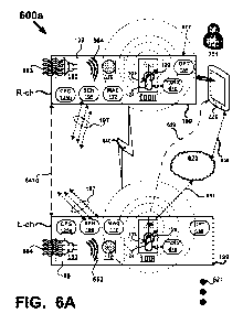
Moving on to FIG. 6A, a user 201 introduces 677 a media device 100ii into an
ecosystem
600a in which another media device 100i already exists. For example, user 201
brings media
device 100ii into sensor proximity 641d of media device 100i such that through
any systems
available to either device, they become aware of each other and their
proximity to each other.
Although, only two media devices are depicted, additional media devices may be
present or may
be introduced into ecosystem 600a as denoted by 621. Further, in subsequent
FIGS., additional
media devices will be introduced into ecosystem 600a to illustrate content
based configuration
and seamless handoff in an ecosystem having a plurality of media devices. User
201 may be
streaming or listening to content 655 on user device 220, such as music from
source 620 such as
a library, playlist, network drive, the Internet, or the cloud, for example.
Continuing with FIG. 6A, user 201 has configured 125a media device 100i to
serve many
roles, such as for example, serving as a speaker phone or conference call
phone, as a speaker to
play back audio content, just to name a few. However, user 201 desires to have
two channel
playback of audio content when two media devices are present in ecosystem
600a. For example,
ecosystem 600a may be an office, a study, bedroom, or other location in which
the user 201 will
listen to audio content using media device(s). Here, media device 100ii has
already been
configured 125b; however, if media device 100ii is not configured at the time
it is recognized by
media device 100i, then the configuration processes described above may be
used to configure
media device 100ii and the configuration of media device 100ii may occur
without any
intervention on part of user 201. For example, media device 100ii may be a
recently purchased
media device that has not been configured to the user's 201 specifications.
APP 225 need not be
used at all to accomplish configuration of media device 100ii. Media device
100i may operate to
24
CA 02906548 2015-09-14
WO 2014/160472 PCT/US2014/026753
configure media device 100ii using the processes described above in reference
to FIGS. 1 ¨ 4B,
or other portions of the present application.
Assuming for purpose of explanation that media device 100ii is already
configured CFG
125b when introduced into ecosystem 600a, the configurations of either device
(e.g., CFG 125a,
CFG 125b, or both) may be used to arbitrate control and role assignment among
the media
devices. In FIG. 6A, an approximate distance 641d between the media devices is
sufficient for
each media device to recognize the other media device using RF 640 detected by
their respective
RF 107 systems, sensor 195 detection via by their respective PROX 113 systems,
acoustic
detection via their respective A/V 109 systems, for example. RF system 107 may
detect BT
transmissions (e.g., via BT 120), WiFi transmissions (e.g., via WiFi 130), Ad
Hoc WiFi
transmission (e.g., via AH 140), or other. Here one or more of the RF
transceivers in RF 107
may be used for detection (e.g., sensing other RF sources or presence due to
changes or
disturbances in RF fields) and communications and is generally denoted as TXRX
610.
Given that media devices 100i and 100ii presently recognize each other and are
configured, the CFG 125a of media device 100i is used to change the role of
media device 100i
from serving as a speaker (e.g., a mono speaker) to serving as a Left channel
speaker L-ch due to
introduction of media device 100ii into ecosystem 600a. Similarly, media
device 100ii change
its role from whatever role it served prior to being introduced into ecosystem
600a to serving as a
Right channel speaker R-ch. Accordingly, a preference of the user 201 to
listen in stereo (e.g.,
L-ch and R-ch) when two media devices (100i and 100ii) are within proximity of
each other may
be accomplished without user 201 intervention based on the configurations in
one or more media
devices (e.g., CFG 125a, CFG 125b, or both).
In one example, media device 100i may wirelessly communicate with media device
100ii
to command, instruct, or otherwise effectuate the role change in media device
100ii. In another
example, media device 100ii may wirelessly communicate with media device 100i
and instruct
media device 100i to change its role to L-ch and media device 100ii through
its CFG 125b is
enabled to effect a change from its present role to the R-ch role when it is
in the presence of
another media device serving in the L-ch role. In another example, one of the
media devices
operates as a master (e.g., 100ii) and the other media device (e.g., 100i)
operates as a slave, and
the master media device changes its role and the role of the slave media
device.
In some examples, a media device in ecosystem 600a may obtain content 659
(e.g.,
audio, video, phone call, etc.) from a user device 220. In other examples, a
media device in
CA 02906548 2015-09-14
WO 2014/160472 PCT/US2014/026753
ecosystem 600a may obtain content 657 from a source 620 that the user device
220 was using
prior to the role change described above. Here, the data payload, data
bandwidth and other
associated with user device 220 obtaining the content 655 is handed over to a
media device in
ecosystem 600a.
FIG. 6B depicts another ecosystem 600b where media devices 100i and 100ii are
already
present in the ecosystem 600b and serving roles as L-ch and R-ch speakers.
Media device 100iii
is introduced 677 into ecosystem 600b. All three media devices are aware of
one another and in
wireless communication 679 with one another. That is, each media device
depicted senses the
presence of the other media devices as was described above. Here, the various
systems in each
media device are not depicted to prevent unnecessarily complicating the
description of FIG. 6B.
Wireless communication between the media devices may be via wireless, optical,
acoustic, or
any combination of those wireless technologies. After being introduced 677
into the ecosystem
600b any one of the media devices may act (e.g., thorough its configuration
CFG 125) to change
a role of a media device in the ecosystem 600b based on may factors including
but not limited to
a type of content the user 201 or user device 220 is using and preferences of
the user 201 when
three media devices are present in ecosystem 600b. In the example depicted,
user 201 prefers a
three media device ecosystem to self-configure into a three speaker
configuration comprised of
left, right, and center channel speakers. In that media devices 100i and 100ii
are already serving
roles and right R-ch and left L-ch speakers respectively, media device 100iii
is re-configured to
serve as the center channel speaker denoted as C-ch. Content 655b, regardless
of its source (e.g.,
user device 220, the internet, cloud, WiFi, etc.) may be serviced by any of
the media devices as
was described in FIG. 6A. Moreover, each media device may process the
information in content
655b based on the type of data it includes. For example, if the content 655b
includes stereo only
data, then media devices 100i and 100ii may be configured to playback the R-ch
and L-ch
information respectively, while media device 100iii is muted because there is
no C-ch
information in the content 655b. In some examples, media device 100iii may
play the role of a
phantom center channel when there is no C-ch information in the content 655b
by, for example,
processing or synthesizing the R-ch and L-ch information to form a phantom
center channel. In
other examples, information in content 655b includes R-ch, C-ch, and L-ch and
all three media
devices serve in their respective assigned roles for a three channel
configuration.
Moving on to FIG. 6C, media device 100i that served in the R-ch role has been
removed
681 from ecosystem 600b and is depicted in dashed outline to reflect that
media device 100i is
26
CA 02906548 2015-09-14
WO 2014/160472 PCT/US2014/026753
no longer present. Remaining media devices 100ii and 100iii are no longer in
communications
with media device 100i and are aware 679 of each other. Accordingly, they
reconfigure into the
user 201 preferred combination of R-ch and L-ch speakers with media device
100iii changing its
role from a C-ch speaker to a R-ch speaker.
In FIG. 6D, the content 655b has changed, at least temporarily, because user
201 receives
an incoming phone call 691. Media devices in ecosystem 600b are aware of user
device 220 and
user's 201 preference that when one or more of the media devices are available
and a phone call
is received, one of the available media devices harvests the content 655b and
changes roles to a
speaker phone or conference phone to handle the audio and/or video content of
the phone call.
Here, media device 100iii which initially served the role of C-ch speaker,
detects the phone call
691, harvests the content 655b, and uses its MIC 170 and SPK 160 to
communicate 693 the
phone conversation with user 201. In that there are three media devices that
could have switched
roles based on content 655b, the CFG 125 of each device may be designed to
arbitrate which of
the three media devices switches roles and harvests the content 655b. For
example: if a single
media device is present, then that device switches roles; if two devices are
present, then the last
device to be introduced into the ecosystem switches roles; if R-ch and L-ch
speakers are present,
then the L-ch speaker switches roles; if R-ch, C-ch, and L-ch speakers are
present, then the C-ch
speaker switches roles; and so on. Any combination of role switching scenarios
may be
programmed or configured, and the foregoing are non-limiting examples.
Referring again to FIG. 6D, in another example, user 201 is wearing a headset
that is also
a media device 100iv. Media device 100iv is aware 679 of the other three media
devices in
ecosystem 600b. In the absence of the other three media devices, media device
100iv is
configured to harvest the content 665b of phone call 691. However, because the
other three
media devices are in fact present, media device 100iv either doesn't take
action on the phone call
691 and media device 100iii switches roles (e.g., as described above) to
harvest the content 655b
and process the call 691, or media device 100iv transfers the call to one of
the other media
devices that may serve as a speaker phone according to the design of CFG 125
in each media
device.
In FIG. 6E, a more populated example of an ecosystem 600e initially includes a
single
media device denoted as 100i. Subsequently, additional media devices are
introduced 677 (e.g.,
677a ¨ 677i) into ecosystem 600e. All media devices are aware 679 of one
another via wireless
means using one or more of the systems depicted in FIG. 1 (e.g., RF, acoustic,
optical, sensors,
27
CA 02906548 2015-09-14
WO 2014/160472 PCT/US2014/026753
etc.). For example: media device 100ii is introduced 677a and devices 100i and
100ii change
roles to become L-Ch and R-ch speakers; next media device 100iii is introduced
677b and it
configures to a front center channel (FC-ch) speaker; next media devices 100iv
and 100v are
introduced 677c and 677d and they configure to rear left and right channel
speakers LR-ch and
RR- ch respectively; next media device 100vi is introduced 677e and it
configures as a rear
center channel (RC-ch) speaker; next media devices 100vii and 100viii are
introduced 677f and
677g and they configure to left and right surround channels LS-ch and RS-ch
respectively; next
media device 100xi is introduced 677h and it configures to a first subwoofer
channel SW1; and
next media device 100xii is introduced 677i and it configures to a second
subwoofer channel
SW2. Media device 100xi and 100xii may be specially designed to serve as low
frequency
transducers (e.g., by their enclosure size and transduce design, such as
woofer size, etc.) and may
automatically configure to that role when introduced into an ecosystem, such
as ecosystem 600e,
for example. Media device 100xi and 100xii may be designed to include full
range drivers such
as tweeter and midrange drivers and also include a low frequency driver for
use as a subwoofer.
Media device 100xi and 100xii may also be designed to include other
transducers such as SPK
160 and MIC 170, for example.
Ecosystem 600e may include more or fewer media devices than depicted in FIG.
6E as
denoted by 621. In general, as media devices are introduced 677 or removed 681
from
ecosystem 600e, remaining media devices may re-configured to serve different
roles based on
content 655b and their respective configurations CFG 125. Here, ecosystem 600e
may be
crafted by user 201 to implement a variety of surround sound formats or data
such as a 2.1, 3.1,
5.1, 7.1, 9.1 format, for example. A plurality of media devices may be
configured to implement
a n.x surround sound format where n and x are both positive integers with n? 1
and x > 0.
Ecosystem 600e may be positioned in a space in the user's home, such as a
media room, family
room, or great room, for example.
Attention is now directed to FIG. 7A where an ecosystem 700a includes four
media
devices 100i, 100ii, 100iii, and 100iv. User 201 and user device 220 are
present in the
ecosystem 700a. Media devices 100i, 100ii, 100iii, and 100iv are aware of and
in wireless
communication with one another as denoted by 779. Wireless communication may
include any
combination of RF via RF system 107, acoustic via A/V system 109, or optical
via OPT 185.
Referring back to FIG. 1, each media device may include the PROX system 113
and its
respective sensor devices SEN 195 in addition to A/V 109, RF 107, and OPT 185
systems. One
28
CA 02906548 2015-09-14
WO 2014/160472 PCT/US2014/026753
or more of those systems may be configured to sense 711 the environment ENV
198 around a
media device for a variety of purposes, such as detecting a presence of
another person 201x (not
shown) in personal proximity of user 201. Personal proximity may include
within hearing range
of speech from the user 201.
User 201 receives a phone call 791 and a decision as to where to route the
content 755b
for handling the phone call is made by media devices 100i, 100ii, 100iii, and
100iv based on
their respective configurations (e.g., CFG 125) which in part are designed to
comport with the
user's 201 needs. Here, user 201 needs the conversation to be private, that
is, not on speaker
phone if other persons 201x are present within the senor range of media
devices 100i, 100ii, and
100iii, and wants to audio portion of content 755b routed to head unit 100iv
to maintain privacy
for the conversation. On the other hand, if no other persons 201x are detected
(e.g., user 201 has
relative privacy) in senor range of media devices 100i, 100ii, and 100iii,
then the user 201 wants
at least the audio portion of content 755b to be routed to one of the media
devices 100i, 100ii,
and 100iii for use as a speaker phone and conversation 793 between the user
201 and the caller
may take place over speaker phone. In some applications where the content 755b
includes video
or audio and video, the user 201 may have configured the media devices (e.g.,
via APP 225) to
route the audio and video to a media device (e.g., to DISP 180) if the user
201 has relative
privacy as detected by the media devices. On the other hand, if user 201 does
not have relative
privacy, then route the audio portion of the content 755b to headset 100iv and
the video portion
of the content to a display on user device 220.
In FIG. 7A, there are no persons 201x within sensor range of media devices
100i, 100ii,
and 100iii. Accordingly, the user's 201 configuration preferences call for the
content to be
routed to media device 100ii, the L-ch speaker. In contrast, in FIG. 7B, at
least one other person
201x is detected in the sensor range 711 of at least one of the media devices
(e.g., 100i). Media
devices 100i, 100ii, 100iii, and 100iv are aware that user 201 likely doesn't
have relative privacy
for the phone call and content 755b is routed to headset 100vi so that the
conversation with the
caller may proceed with privacy due to the presence of 201x (e.g., within
earshot of user 201).
As another example of sensing the environment ENV 198 around a media device
for a
variety of purposes, in FIG. 7B, there may be another device 720 within
sensing range 711 of
media devices 100i, 100ii, 100iii, and 100iv. Here, RF system 107 may use one
of its
transceivers, the antenna 124 configured to be de-tuned 129 to detect the RF
emissions 721 of
device 720. Based on those sensory inputs, user 201 may configure the media
devices 100i,
29
CA 02906548 2015-09-14
WO 2014/160472 PCT/US2014/026753
100ii, 100iii, and 100iv to regard the space around the user 201 as not be
private and route
content 755b to the headset 100iv to maintain privacy for the conversation.
Although the foregoing examples have been described in some detail for
purposes of
clarity of understanding, the above-described inventive techniques are not
limited to the details
provided. There are many alternative ways of implementing the above-described
invention
techniques. The disclosed examples are illustrative and not restrictive.