Note: Descriptions are shown in the official language in which they were submitted.
CA 02907048 2015-09-15
WO 2014/151045 PCT/US2014/024830
- 1 -
LOW POROSITY AUXETIC SHEET
TECHNICAL FIELD
[0001] The
present disclosure relates generally to solids having engineered void
structures.
BACKGROUND
[0002]
There are many examples of solids having engineered void structures, such
engineered void structures provide a wide variety of mechanical, acoustic and
thermal
characteristics particular to the material and application.
[0003]
U.S. Pat. No. 5,233,828 discloses an example of an engineered void structure
for a
gas turbine combustor liner. The operating temperature of the gas turbine
combustor is near,
and can exceed, 3,000 F.
Consequently, the combustor liner is provided within the
combustor to insulate the engine surroundings and prevent thermal damage to
other
components of the gas turbine. To minimize temperature and pressure
differentials across the
combustor liners, cooling slots have conventionally been provided, such as is
shown in U.S.
Pat. No. 5,233,828, in the form of spaced cooling holes disposed in a
continuous pattern.
[0004] WO
2008/137201 discloses another example of an engineered void structure for a
gas turbine combustor liner. In WO 2008/137201, the liner comprises a
plurality of small,
closely-spaced film cooling holes to provide a cooling film along a hot side
of the liner (i.e.,
the side facing the hot combustion gases) from the cold side of the liner
(i.e., the side in
contact with the relatively cooler air in an adjacent passage). These cooling
holes are
disclosed to have a non-uniform diameter through the thickness of the liner,
with the cold
side holes having a first diameter that is smaller than the second diameter at
the hot side, thus
providing an aspect ratio other than 1.0 (e.g., a ratio of the second diameter
to the first
diameter may be 3.0 to 5.0).
[0005]
U.S. Pat. No. 8,066,482 shows another example of a combustor liner having a
particular engineered void structure, wherein the voids comprise elliptical
shaped cooling
holes having a first size at a cool side and a second, larger size at a hot
size, thus presenting
an aspect ratio greater than one. U.S. Pat. No. 8,066,482 further discloses
that the elliptical
CA 02907048 2015-09-15
WO 2014/151045 PCT/US2014/024830
- 2 -
shaped cooling holes are oriented parallel to the stress field so that the
radius of curvature
spreads the stress field and reduces stress concentrations.
[0006] EP 0971172 Al likewise shows another example of a perforated liner
used in a
combustion zone of a gas turbine.
[0007] Currently, combustors liners such as those noted above are designed
with a
specific void structure or porosity, variously defined as the ratio of the
area of holes relative
to the area of the structure or as the ratio of the volume of holes relative
to the volume of the
structure, as applicable. Known elliptic voids have an aspect ratio of up to
50 in order to
obtain the intended cooling behavior, but these known elliptic voids result in
a very high
stress at the tip.
[0008] FIG. 1(a) is a graph of Poisson's Ratio, u, on the Y-axis against
Strain on the X-
axis, illustrating the negative Poisson's Ratio behavior of both experimental
test results
conducted on a rubber test specimen (denoted by circular data points) and
numerical test
results (Finite Element Modeling)(denoted by the solid line bounded between
the upper and
lower dashed lines). The vertical dashed line denotes the Nominal Strain, cc,
the point at
which critical true plastic strain is reached, which was -0.05 as indicated.
Continuing levels
of strain, as shown in the progression of FIGS. 1(b)-1(d) produced
consistently lower and
lower values for Poisson's ratio until finally it crossed zero and turned
negative. In these
studies, it was determined that if the porous test specimen was deformed
strongly enough, a
state of a negative Poisson's ratio ("NPR") could be consistently exhibited.
Thus, although
rubber conventionally exhibits a positive Poisson's ratio, as most
conventional materials, the
particular arrangement of elliptical holes was determined to cause the
positive Poisson's ratio
to exhibit pseudo-auxetic properties.
SUMMARY
[0009] Aspects of the present disclosure are directed to a solid, such as a
solid sheet,
having an engineered void structure that causes a solid having a positive
Poisson ratio to
exhibit pseudo-auxetic behavior upon application of stress to the solid.
Accordingly, a
material having a positive Poisson ratio can be structurally modified to
microscopically
behave as a material having a negative Poisson ratio (e.g., the material would
expand laterally
if subjected to a tensile force, or contract if subjected to a compressive
force) in accord with
the present concepts.
CA 02907048 2015-09-15
WO 2014/151045 PCT/US2014/024830
- 3 -
[0010]
When materials are compressed along a particular axis they are most commonly
observed to expand in directions orthogonal to the applied load. The property
that
characterizes this behavior is the Poisson's ratio, which is defined as the
ratio between the
negative transverse and longitudinal strains. The majority of materials are
characterized by a
positive Poisson's ratio, which is approximately 0.5 for rubber and 0.3 for
glass and steel.
Materials with a negative Poisson's ratio will contract (expand) in the
transverse direction
when compressed (stretched) and, although they can exist in principle,
demonstration of
practical examples is relatively recent. Discovery and development of
materials with negative
Poisson's ratio, also called auxetics, was first reported by Lakes in 1987.
Investigations
suggest that the auxetic behavior involves an interplay between the
microstructure of the
material and its deformation. Examples of this are provided by the discovery
that metals with
a cubic lattice, natural layered ceramics, ferro-electric polycrystalline
ceramics, and zeolites
may all exhibit negative Poisson's ratio behavior.
Moreover, several geometries and
mechanisms have been proposed to achieve negative values for the Poisson's
ratio, including
foams with reentrant structures, hierarchical laminates, polymeric and
metallic foams
[0011]
Negative Poisson's ratio effects have also been demonstrated at the micrometer
scale using complex materials which were fabricated using soft lithography and
at the
nanoscale with sheets assemblies of carbon nanotubes. A significant challenge
in the
fabrication of materials with auxetic properties is that it usually involves
embedding
structures with intricate geometries within a host matrix. As such, the
manufacturing process
has been a functional limitation in the practical development towards
applications. A
structure which forms the basis of many auxetic materials is that of a
cellular solid and
research into the deformation these materials is a relatively mature field
with primary
emphasis on the role of buckling phenomena on load carrying capacity and
energy absorption
under compressive loading. Very recently, the results of a combined
experimental and
numerical investigation demonstrated that mechanical instabilities in 2D
periodic porous
structures can trigger dramatic transformations of the original geometry.
Specifically,
uniaxial loading of a square array of circular holes in an elastomeric matrix
is found to lead to
a pattern of alternating mutually orthogonal ellipses. This results from an
elastic instability
above a critical value of the applied strain. The geometric reorganization
observed at the
instability is both reversible and repeatable and it occurs over a narrow
range of the applied
load. Thus, this behavior provides opportunities for transformative materials
with properties
CA 02907048 2015-09-15
WO 2014/151045 PCT/US2014/024830
- 4 -
that can be reversibly switched. Moreover, it has been shown that the pattern
transformation
leads to unidirectional negative Poisson's ratio behavior for the 2D
structure, i.e., it only
occurs under compression. The uncomplicated manufacturing process of the
samples together
with the robustness of the observed phenomena suggests that this may form the
basis of a
practical method for constructing planar auxetic materials over a wide range
of length-scales.
[0012] According to one aspect of the present disclosure, a low porosity
sheet material
comprising an arrangement of elongated void structures, each of the elongated
void structures
including one or more substructures, a first plurality of first elongated void
structures and a
second plurality of second elongated void structures, each of the first and
second elongated
void structures having a major axis and a minor axis, the major axes of the
first elongated
void structures being perpendicular to the major axes of the second elongated
void structures,
the first and second pluralities of elongated void structures being arranged
in an array of rows
and columns, each of the rows and each of the columns alternating between the
first and the
second elongated void structures, wherein a porosity of the elongated void
structures is below
about 10%.
[0013] In accord with another aspect of the present disclosure, a method
for forming a
pseudo-auxetic material includes the acts of providing a body that is at least
semi-rigid and
forming in the body first elongated void structures and second elongated void
structures.
Each of the elongated void structures have a major axis and a minor axis, the
major axes of
the first elongated void structures being at least substantially perpendicular
to the major axes
of the second elongated void structures, the elongated void structures being
arranged in an
array of rows and columns, each of the rows and each of the columns
alternating between the
first and the second elongated void structures, wherein the elongated void
structures are sized
to exhibit a negative Poisson's ratio behavior under stress.
[0014] The above summary is not intended to represent each embodiment or
every aspect
of the present disclosure. Rather, the summary merely provides an
exemplification of some
of the novel features presented herein. The above features and advantages, and
other features
and advantages of the present disclosure, will be readily apparent from the
following detailed
description of exemplary embodiments and modes for carrying out the present
invention
when taken in connection with the accompanying drawings and the appended
claims.
CA 02907048 2015-09-15
WO 2014/151045 PCT/US2014/024830
- 5 -
BRIEF DESCRIPTION OF THE DRAWINGS
[0015] FIGS. 1(a)-1(d) are, respectively, a Strain vs. Poisson Ratio plot
of experimental
data and computer modeling data for a solid comprising elliptical through
holes and
representations of the structure corresponding to specific data points from
the plot.
[0016] FIG. 2 is a representation of a load path in a solid having an
engineered void
structure comprising elliptical holes providing a 40% porosity.
[0017] FIG. 3 is a representation of a load path in a solid having an
engineered void
structure comprising an arrangement of slots and stop holes according to
aspects of the
present disclosure.
[0018] FIG. 4 is a representation of a load path in a solid having an
engineered void
structure comprising an arrangement of slots according to aspects of the
present disclosure.
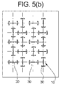
[0019] FIGS. 5(a)-5(b) depict examples of an engineered void structure
comprising an
arrangement of through holes according to aspects of the present concepts
comprising,
respectively, large aspect ratio ellipses and double-T shaped slots.
[0020] FIG. 6 shows a representation of a material in accord with aspects
of the present
concepts including an arrangement of engineered void structures enabling the
material to
exhibit Negative Poisson Ratio (NPR) behavior.
[0021] FIG. 7 shows a representation of a unit cell in the material
comprising engineered
void structures in accord with FIG. 6 according to aspects of the present
concepts.
[0022] FIGS. 8(a)-8(c) depict examples of a solid having an engineered void
structure
comprising an arrangement of through holes according to aspects of the present
disclosure,
showing a flow of stress between adjacent unit locations responsive to an
applied localized
thermal stress (shown in FIG. 8(b)).
[0023] FIGS. 9-30 depict various aspects of and examples of the concepts
disclosed
herein.
[0024] While aspects of this disclosure are susceptible to various
modifications and
alternative forms, specific embodiments have been shown by way of example in
the drawings
and will be described in detail herein. It should be understood, however, that
the invention is
not intended to be limited to the particular forms disclosed. Rather, the
invention is to cover
all modifications, equivalents, and alternatives falling within the spirit and
scope of the
invention as defined by the appended claims.
CA 02907048 2015-09-15
WO 2014/151045 PCT/US2014/024830
- 6 -
DETAILED DESCRIPTION
[0025] This invention is susceptible of embodiment in many different forms.
There are
shown in the drawings and will herein be described in detail representative
embodiments of
the invention with the understanding that the present disclosure is to be
considered as an
exemplification of the principles of the invention and is not intended to
limit the broad
aspects of the invention to the embodiments illustrated.
[0026] For purposes of the present detailed description, unless
specifically disclaimed:
the singular includes the plural and vice versa; the words "and" and "or"
shall be both
conjunctive and disjunctive; the word "all" means "any and all"; the word
"any" means "any
and all"; and the words "including" and "comprising" mean "including without
limitation."
Moreover, words of approximation, such as "about," "almost," "substantially,"
"approximately," and the like, can be used herein in the sense of "at, near,
or nearly at," or
"within 3-5% of," or "within acceptable manufacturing tolerances," or any
logical
combination thereof, for example.
[0027] FIG. 6 shows a representation of a material in accord with aspects
of the present
concepts including an arrangement of engineered void structures 10 (comprising
one or more
substructures, such as an elongated structure 104 and stress reducing
structures 102 at either
end of the elongated structure) enabling the material to exhibit Negative
Poisson Ratio (NPR)
behavior. As is further represented in FIG. 6, when the structure, and more
particularly the
indicated unit cell 200, is subjected to a compressive force as represented by
the arrow
pointing in the -Y direction, the compressive force causes a moment 210 around
the center of
each unit cell 200, causing the cells 200 to rotate. Each cell 200 in turn
affects the
neighboring unit cells 200, such effect being attributable to the way the
adjacent voids or
openings 100 (which may comprise one or more substructures 102, 104), are
arranged in
accord with aspects of the present concepts.
[0028] Although the engineered void structures 10 shown in FIG. 6 are shown
to be
double-T slots, by way of example, other engineered void structures (e.g.,
large aspect ratio
ellipses, other slot shapes, etc.) could be used and would result in a similar
NPR behavior.
[0029] The forces acting on an individual unit cell 200 are represented, by
way of
example, in FIG. 7, where FE represents the applied external force, F1,2
represents the applied
CA 02907048 2015-09-15
WO 2014/151045 PCT/US2014/024830
- 7 -
force from the adjacent neighboring cell to the left (as shown, array location
Fx,y), F2,3
represents the applied force from the adjacent neighboring cell below, and
F1,4 represents the
applied force from the adjacent neighboring to the right. Each unit cell 200
rotates in a
direction opposite to that of its immediate neighbors, as shown in FIG. 6.
This rotation
results in a reduction in the X-direction distance between horizontally
adjacent cells. In other
words, compressing the structure in the Y direction, such as in the manner
indicated in FIG. 6
by the arrow pointing in the ¨Y direction, causes the material comprised of
the unit cells 200
to contract in the X direction, thus exhibiting "pseudo-auxetic" or NPR
behavior.
Conversely, tension in the +Y direction results in expansion in the X
direction, again
expressing "pseudo-auxetic" or NPR behavior. At the scale of the entire
structure, this
mimics the behavior of an auxetic material despite the materials forming the
unit cells 200
consisting of conventional positive Poisson ration material.
[0030] Turning to FIG. 2, the engineered void structure 10 utilized in the
studies of FIGS.
1(a)-1(d) is shown, emphasizing a representation of a load path in the solid
material. In this
example, the engineered void structure comprises elliptical holes 12 defining
a 40% porosity.
These elliptical holes 12 have a strong curvature and, consequently, a high
stress and
plasticity with a correspondingly shortened lifespan. The arrows indicate
points of maximum
curvature of the ellipse and, hence, points of maximum stress.
[0031] Although demonstrating proof of the concepts disclosed herein, the
sample
material having a 40% porosity, as depicted in FIG. 2, would not be suitable
for all
applications. By way of example, the aforementioned gas turbine combustor
liners typically
seek to utilize materials (e.g., annular sheets of material) having a porosity
of between about
1-3%, with the actual porosity depending on the particular design goals for a
given
application (e.g., thermal transfer, acoustics, life span, etc.).
[0032] FIG. 3 is a representation of another solid having engineered void
structures 10, in
accord with at least some aspects of the present concepts, comprising an
arrangement of slots
20 and stop holes 15 (disposed at each end of a slot 20). This arrangement of
slots 20 and
stop holes 15 exhibits little curvature, as compared to the ellipses 12 of
FIG. 1, and
consequently exhibits a low stress and low plasticity with a correspondingly
lengthened
lifespan. A load path is shown and the arrows indicate points of maximum
curvature of the
ellipse and, hence, points of maximum stress. The stop holes 15 are used to
stop crack
CA 02907048 2015-09-15
WO 2014/151045 PCT/US2014/024830
- 8 -
propagation and are placed at the end of the straight slot 20 in order to
reduce the stress at
this location. The slot 20 length is sized in order to generate an intended
behavior.
[0033] In contrast to the ellipses 12 of FIG. 2, the arrangement of slots
20 and stop holes
15 of FIG. 3 exhibits a porosity of only about 3-4%, which renders this
structure suitable for
particular applications involving gas turbine combustors. Of course, for such
applications,
the structure would be embodied within materials suitable for such application
including, but
not limited to, polycrystalline or single-crystal nickel-base, iron-nickel-
base and cobalt-base
superalloys or other high-temperature, corrosion-resistant alloys, without
limitation.
Examples of such alloys include, but are not limited to, Inconel (e.g. IN600,
IN617, IN625,
IN718, IN X-750, etc.), Waspaloy, Rene alloys (e.g. Rene 41, Rene 80, Rene 95,
Rene N5),
Haynes alloys (e.g., Hastelloy X), Incoloy, MP98T, TMS alloys, and CMSX (e.g.
CMSX-4)
single crystal alloys.
[0034] Again, it is to be emphasized that the engineered void structures 10
disclosed by
way of example herein enable ordinary positive Poisson ratio materials, such
as the
superalloys noted above, to exhibit "pseudo-auxetic" or NPR behavior. A
combustor liner,
by way of example, is made from a material comprising a specific void
structure for the
intended application. In contrast to conventional materials utilizing known
patterns of elliptic
voids having an aspect ratio of up to 50 in order to get the intended behavior
(and resulting in
a very high stress at the tip), engineered void structures 10 as disclosed
herein, such as slots
30 with stress relief features 35 (as discussed below), are able to provide a
smaller porosity
and, hence, let less air through.
[0035] FIG. 4 is a representation of a load path in a solid having an
engineered void
structure 10 comprising an arrangement of slots 30 according to aspects of the
present
disclosure. In the example shown, the slots 30 are double-T slots with stress-
reducing
structures 35 at each end of each slot 30. In the depicted stress-reducing
structures 35, the
horizontal part of the "T" curves back in the shape of an ellipse with a large
curvature at the
junction to the vertical section in order to reduce the stress at this
location. The slot 30, the
vertical part of the "T," is a straight slot sized in length in order to
generate an intended
behavior. As with the arrangement of FIG. 3, this arrangement of slots 30
exhibits little
curvature, as compared to the ellipses of FIG. 2, and consequently exhibits a
low stress and
low plasticity with a correspondingly lengthened lifespan. The arrows indicate
points of
CA 02907048 2015-09-15
WO 2014/151045 PCT/US2014/024830
- 9 -
maximum curvature of the ellipse and, hence, points of maximum stress. In
contrast to the
ellipses 12 of FIG. 2, the slots 30 of FIG. 4 exhibit a porosity of only about
1-2%.
[0036] As to the double-T slot structures 30, 35, lowering a degree of
curvature of the
stress-reducing structures 35 in turn lowers the stress. At the junction of
the slot 30 and the
stress-reducing structures 35, the curvature is generally flat, which
distributes stresses over a
larger part of that length producing significant local stress reduction.
[0037] In general, the disclosed engineered void structures can be applied
to any solid
material (e.g., concrete, metal, etc.) and is not limited to, for example, gas
turbines or gas
turbine combustors. In the exemplary combustor application, however, the
disclosed
engineered void structures 10 advantageously produce macroscopic pseudo-
auxetic behavior
(negative Poisson's ratio) with significantly reduced porosity, hence air
usage for cooling and
damping. Even if this structure were to be made from a "conventional" alloy
suitable for
such application, it will contract in lateral direction when it is put under
axial compression
load, without the metal from which it is made having a negative Poisson's
ratio. The
behavior is, as noted, triggered by the specific engineered void structure
itself.
[0038] FIGS. 5(a)-5(b) depict examples of engineered void structures 10
according to
aspects of the present concepts comprising respectively, large aspect ratio
ellipses 60 and
double-T shaped slots 30, respectively. The engineered void structure 10
pattern in accord
with the present concepts comprises horizontal and vertical structures (e.g.,
slots in the shape
of a double T, slots with stop holes, large aspect ratio ellipses, etc.)
arranged on horizontal
and vertical lines in a way that the lines are equally spaced in both
dimensions (also Ax=Ay).
Centers of the slots are on the crossing point of the lines and vertical and
horizontal slots
alternate on the vertical and horizontal lines. Vertical slots are surrounded
by horizontal slots
along the lines (and vice versa) and the next vertical slots are found on both
diagonals. The
slot pattern on the outside of a cylindrical component is equivalent to the
pattern on the sheet
(vertical = axial, horizontal = circumferential). However, in such
construction, the slot shape
on the inside is different due to the different radius of this surface. Axial
slots have a smaller
short axis than on the outside but a larger long axis. Circumferential slots
have a larger short
axis than on the outside but a shorter long axis.
[0039] Manipulation of the geometry of the arrangements of engineered void
structures
in accord with the present concepts can control the manifested Poisson's
ratio. By
increasing the length(s) of these innovative features, a Poisson's ratio can
be tailored, as
CA 02907048 2015-09-15
WO 2014/151045 PCT/US2014/024830
- 10 -
desired. For example, the major axis of the ellipses 60 in FIG. 5(a) can be
increased or
decreased in effect to control the Poisson's ratio. The minor axis of the
ellipses itself
provides variability in the effective Poisson's ratio, but is only of a second
order influence on
the achievable value on the negative Poisson ratio. Likewise, for other
arrangements of
engineered void structures 10 in accord with the present concepts, such as the
double-T slot,
the elongated slot structure (e.g., 104; FIG. 6) is of a first order influence
on the negative
Poisson ratio and the stress-reducing features or shorter transverse
structures are of a second
order influence (at least individually), with the enabled rotation of the unit
cells 200 enabling
(see, e.g., FIG. 6) generating the pseudo-auxetic behavior.
[0040] In at least some aspects of the present concepts, the aforementioned
test specimen
noted above with respect to FIGS. 1(a)-1(d) can be subjected to a load to
determine the
change in the Poisson ratio as the test specimen is deformed under load. At a
certain level of
deformation the "instantaneous" Poisson ratio can be determined and plotted
against some
parameter representing the level of deformation. A designer of a system or
component, after
deciding what Poisson ratio would be suitable for that particular application,
can then
determine (e.g., using a look-up table, etc.) the corresponding level of
deformation
corresponding to the target Poisson ratio and the geometry of the holes at
that condition is
then determined. This hole geometry can then be machined (manufactured) on an
unstressed
part to achieve a component with the desired Poisson ratio.
[0041] FIGS. 8(a)-8(c) depict examples of a solid having an engineered void
structure 10
comprising an arrangement of through holes according to aspects of the present
disclosure,
showing a substantially steady state condition (FIG. 8(a)), an applied
localized thermal stress
75 (FIG. 8(b)), and a flow of stress (arrows 85) between adjacent unit
locations responsive to
the applied localized thermal stress (FIG. 8(c)). In accord with the present
concepts, a
material comprising an engineered void structure 10 as disclosed herein,
responsive to a hot
spot compressive stress in one direction, causes the positive Poisson ratio
material to exhibit
NPR properties and contract in the other direction, reducing the thermal
stress in this
direction. The mechanism also works vice versa, so the thermal stress induced
by a hot spot
gets strongly reduced in all directions. This effect is stronger than just the
impact of the
reduced stifthess. Stress at hot spot is reduced by 50%, leading to an
increase in stress
fatigue life by several orders of magnitude.
CA 02907048 2015-09-15
WO 2014/151045 PCT/US2014/024830
- 11 -
[0042] As another benefit to the engineered void structures 10 disclosed
herein, slots with
stop holes (e.g., FIG. 3) or double-T slots (e.g., FIG. 4) removes less
material from the sheet
in which they are formed, hence expediting manufacture. Further, as previously
noted, slots
with stop holes (e.g., FIG. 3) or double-T slots (e.g., FIG. 4) have
significantly less void
fraction (lower porosity), resulting in a drastic reduction in air usage
(e.g., as used in gas
turbine applications).
[0043] The void structures 10 disclosed herein can advantageously be formed
in different
sizes and/or geometries in relation to the application. By way of example, a
cooling or
damping hole in a gas turbine hot section component is typically in the range
of about 0.5mm
to 3mm in diameter. In such an application, the void structures 10 in accord
with the present
aspects of the invention would be configured with approximately the same cross
sectional
area to facilitate the same degree of air flow. Where slots with stop holes
(e.g., FIG. 3) are
provided, the stop holes could just take the place of the conventional hole
configuration.
Hence the hole might cover the same diameter range of about 0.5mm to 3mm and
be spaced
apart between 2mm to 20mm. The slot would bridge the distance between two
adjacent
holes. Similarly, as to the sizing of the slots and transverse stress reducers
in the double-T
slot (see, e.g., FIG. 4), the longitudinal length of the double-T slot has the
same dimension as
in the previous shape, so between 2mm and 20mm. The transversal extension for
stress
reduction might be between 10% and 50% of the longitudinal length. Regarding
the large
aspect ratio ellipse, the long axis dimension (tip to tip) is expected to be
between 2mm and
20mm and have an aspect ratio between 5 and 50.
[0044] The size of the voids is influenced by the thickness of the
component and the
manufacturing method. The exemplary, non-limiting dimensions above are mainly
related to
laser manufacturing and an operation in a mildly dusty environment such as a
gas turbine
engine. Under clean air conditions, for example, the feature size could be
reduced and then
the void could be manufacture by electron beam cutting at approximately 1/10
of the size
given above or smaller.
[0045] While many embodiments and modes for carrying out the present
invention have
been described in detail above, those familiar with the art to which this
invention relates will
recognize various alternative designs and embodiments for practicing the
invention within the
scope of the appended claims. For example, each of the engineered void
structures 10
disclosed herein may comprise a single structure (e.g., large aspect ratio
ellipses) or plural
CA 02907048 2015-09-15
WO 2014/151045 PCT/US2014/024830
- 12 -
structures (e.g., a slot with stress reducers at each end). These structures
may be formed in an
existing material and/or formed during the formation process of the material
using any
processing method such as, but not limited to, laser cutting, electron beam
cutting, water jet
cutting, photolithography (optical lithography, UV lithography, etc.), or
micro fabrication.
[0046] It is to be understood that although each of the embodiments
described herein
utilized the same structures uniformly, the present concepts include utilizing
different
structures disclosed herein in combination. For example, an arrangement of
void structures
in a single structure, in accord with the present concepts, may include a
combination of
any of large aspect ratio ellipses and/or a slot with stress reducers and/or a
slot with stop
holes at both ends and/or double-T shaped slots.
[0047] Moreover, the shapes of the voids disclosed herein are not limiting.
Different
shapes can be used in accord with the present concepts, so long as the NPR
behavior shown
in FIG. 6 is achieved and the unit cells rotate in the respective directions
described. The
shapes of the voids can be selectively changed based on the requirements of
the application.
[0048] Further, appended hereto are slides corresponding to application of
the present
concepts to a structure formed of metal, as contrasted to a conventional
structure having a
regular array of circular through holes, demonstrating that the present
concepts work in metal
as well as the tested rubber.