Note: Descriptions are shown in the official language in which they were submitted.
CA 02907486 2015-09-16
WO 2014/172504 PCT/US2014/034432
1
SYSTEM AND METHOD FOR UNIPOLAR SEPARATION OF EMULSIONS AND
OTHER MIXTURES
Cross Reference to Related Applications
[0001] This application claims priority to and the benefit of, and
incorporates herein by
reference in its entirety, U.S. Provisional Patent Application 61/812,700,
filed April 16, 2013,
titled "Systems and Methods for Unipolar Emulsion Separation."
Field of Invention
[0002] This invention relates generally to separation of two or more phases
of an emulsion or
other mixture. In certain embodiments, the invention relates to separation of
liquid phases in an
emulsion or other mixture by coalescing like-charged droplets.
Background of the Invention
[0003] Emulsions appear in a wide range of industries, for example,
petrochemical processing,
food processing, metal finishing and polishing, textile, paper, cosmetic,
pharmaceutical,
biotechnology, as well as other industries. It is often necessary to perform
separations of one or
more components of these emulsions, for example, separation of an aqueous
liquid phase (e.g.,
water) from a non-aqueous liquid phase (e.g., oil) in an emulsion that is
composed of either
predominately aqueous phase or predominately non-aqueous phase.
[0004] For example, in petroleum industries, water is considered a
contaminant of the oil
products and must be separated from the oil product before further processing,
because water
may cause considerable corrosion of the processing equipment and may affect
the life of the
CA 02907486 2015-09-16
WO 2014/172504 PCT/US2014/034432
2
equipment, which may negatively impact the entire plant. Even trace amounts of
water in the oil
may cause serious problems further down the line. In a contrasting example,
oils are a common
pollutant in downstream wastewater and byproducts produced in the food and
metal industries
and should be separated from the wastewater. Separating oil from water
(including trace
amounts of oil) is a significant challenge. In order to be released back into
environment,
government regulations require that the oil does not contain more than certain
amounts of oil in
the water. The maximum allowed quantity of oil for may be 10 ppm of oil or
less.
[0005] A significant challenge is to reduce the capital costs of energy
consumption and reduce
or eliminate the use of chemical additives (especially those additives that
are considered
pollutants and/or additives that otherwise have a negative environmental
effect), which are the
traditional method of promoting the breakup of emulsions and other mixtures
into their
components. Another significant challenge is achieving desired levels of
separation of oil and
water.
[0006] There are a number of traditional methods for separating components
of emulsions.
One of the most common separation techniques is gravity separation. As a
primary and low cost
treatment step, gravity separation is typically used for separation of
emulsions with larger droplet
sizes. Gravity separation may be accompanied by a sedimentation process. For
example, oil
may adhere to the surface of solid particles and be effectively removed by
sedimentation.
However, gravity separation is not effective for destabilization of emulsions
with small droplet
sizes, because the time of sedimentation is impractically long (the required
time is roughly
inversely proportional to the droplet size squared).
[0007] In order to separate emulsions with fine droplets, emulsions are
typically pretreated
chemically to promote coagulation and increase floc size, thereby
destabilizing the emulsified
CA 02907486 2015-09-16
WO 2014/172504 PCT/US2014/034432
3
phase during gravity separation. In some conventional methods, the emulsion
may also be
heated to reduce the viscosity, induce stronger density difference, and reduce
the surface tension
of the stabilizing films between droplets. Other chemical treatment methods
increase the acidity
or add ionic agents to the emulsion to neutralize the charge of droplets.
Chemical treatment
methods are energy intensive and may introduce several undesired chemical
contaminants.
Separation of the additional chemical contaminant may require post-processing
unit operations
for separation of chemicals, resulting in increased cost and greater risk of
environmental
pollution.
[0008] In addition to gravity separation, other physical methods for
destabilizing emulsions
include heating, centrifugation, filtration, ultrafiltration (e.g., using
membranes), and reverse
osmosis. Ultrafiltration (e.g., membrane ultrafiltration) has a smaller
chemical footprint than
gravity separations and can be somewhat effective for emulsions with small
droplet sizes (e.g.,
smaller than 100 gm). However, the costs associated with ultrafiltration tend
to be high (or
prohibitive) due to high energy consumption required for ultrafiltration of
large volumes, and due to
degeneration of the membrane coating materials over time (e.g., such that new
membranes need to be
provided on a regular basis, further increasing the costs).
[0009] Another physical method for separating components of emulsions is
electrostatic separation.
There are three electrostatic body forces that can be used to induce
coalescence. The electric body force
in a dielectric liquid, that results from an imposed electric field, can be
expressed as:
1 2, 1 2 OE
f = ppLf VC+-V
2 2 OP ,
(1)
where pc is volume charge density, 8 is the fluid permittivity, p is the fluid
density, and T is the fluid
CA 02907486 2015-09-16
WO 2014/172504 PCT/US2014/034432
4
temperature. The first term on the right hand side of Eq. (1) is the
electrophoretic, or Coulombic, force that
results from the net free space charges in the fluid. The second term, known
as the dielectrophoretic force,
arises ftom the permittivity gradient. The last term, called the
electrostrictive force, is important only for
compressible fluids.
[0010] In these electrostatic separators, it is primarily the second term,
dielectriphoretic force, which
is exploited to promote the coalescence of droplets in the emulsion. In one
conventional technique, two
parallel plates are immersed in the emulsion with a small gap spacing between
the electrodes. These
immersed electrodes are used to induce an external electric field to the bulk
of the emulsion. The water
droplets in the medium become polarized and positive-negative ends attract
each other so that the oil film
between two droplets squeezes and is drained. The two adjacent drops may merge
together when the
layer of the oil between them is ruptured. These droplets do not acquire a net
charge. One limitation of
this technique is that the polarization force is scaled with the size of
droplet. The smaller the droplet size,
the larger the field that must be applied. Moreover, the orientation of two
adjacent droplets is important.
If the angle is not appropriate, two droplets repel rather attract and they
cannot be merged ¨ this is a
significant limitation of conventional electrostatic separators. The
electrohydrodynamic-induced
flow and bi-polar attraction (positive-negative attraction) caused by the
applied electrophoretic
force may induce coalescence of droplets.
[0011] The electrohydrodynamic flow generated by interactions of the
electric field and fluid
flow may also increase the chance of droplet coalescence. AC and DC fields
have been used to
establish homogeneous or nonhomogeneous fields between the immersed
electrodes.
Electrostatic separators may be effective in separating droplets as small as a
few hundred microns;
however, these separators are not effective for smaller droplet sizes in
moderate electrical fields.
[0012] Although electrostatic separators show some promise, they also
suffer from several
CA 02907486 2015-09-16
WO 2014/172504 PCT/US2014/034432
significant limitations. In conventional electrocoalescencers, both electrodes
are
immersed in the emulsions. The immediate consequence is that the technique
cannot be
reliably used when the content of water in the emulsion is high, for example,
greater than 40
wt.%. The high content of water may limit the level of applied potential to
the electrodes so that
even moderate fields may cause electrostatic breakdown. Even when the content
of water is
moderate or low, the separated water droplets tend to align themselves in the
direction of the
imposed field and form a chain-like structure across the gap between the
electrodes. The
formation of this chain may increase the chance of electrostatic discharge and
arc across the gap.
The electrostatic discharge poses a risk of explosion, as well as corrosion of
the electrode or
electrode coatings, and increased contamination due to chemical decomposition
of oil around the
electrodes. Moreover, the electrostatic discharge/breakdown may reduce the
rate of
coalescence by suppressing the strength of the background electric field, the
rate of charging
the droplets, and the efficiency of the separator. Additionally, traditional
electrostatic separators
fail where the aqueous phase has high salt content.
[0013] A separation method is needed that is cost-effective, works for
emulsions having
small droplet size, works irrespective of the salt concentration of the
aqueous phase, and does not
pose a risk of explosion or require addition of chemical additives to the
emulsion.
Summary of the Invention
[0014] Various embodiments of the invention relate to methods and systems
for separating
two or more phases of an emulsion or other mixture. In certain embodiments,
the invention
introduces a net and unipolar charge into the mixture such that adjacent
droplets therein acquire
net and unipolar charges and, surprisingly, enhance coalescence of like-phase
droplets, thereby
CA 02907486 2015-09-16
WO 2014/172504 PCT/US2014/034432
6
destabilizing the mixture and producing, or enhancing production of, two or
more consolidated
liquid phases.
[0015] Some embodiments discussed herein provide successful separation of
two or more
phases of an emulsion or other mixture despite high conductivity of a
dispersed phase, despite
high salt content, and/or despite the presence of a surfactant or other
emulsifier. In some
embodiments, the conductivity of the mixture is between 1 mS/m to 1 S/m or as
high as 10 S/m.
The systems and methods described herein are applicable to a wide variety of
electrical
conductivity ranges. Certain embodiments described herein can separate a
variety of mixtures
having wide ranges of salt and/or surfactant content without any special
adjustment in
configuration of electrodes or other invasive manipulation.
[0016] In one aspect, the invention provides a method for separating two or
more phases of a
mixture (e.g., an emulsion), the method including the steps: (a) providing the
mixture with a net
and unipolar charge (e.g., such that adjacent droplets therein acquire net and
unipolar charges),
thereby enhancing coalescence of like-phase droplets therein and producing, or
enhancing the
production of, two or more consolidated phases; and (b) collecting the two or
more consolidated
phases.
[0017] In certain embodiments, step (a) includes bombarding the mixture
with ions
via corona discharge.
[0018] In certain embodiments, step (a) includes providing an emitter
electrode (e.g., sharp
electrode) and a collector electrode, wherein at least the collector electrode
(e.g., blunt electrode)
is in physical contact with the mixture and a potential difference is applied
between the emitter
electrode and the collector electrode at or above a corona discharge
threshold.
[0019] In certain embodiments, the emitter electrode is not in physical
contact with the
CA 02907486 2015-09-16
WO 2014/172504 PCT/US2014/034432
7
mixture.
[0020] In certain embodiments, a gaseous medium (e.g., nitrogen, oxygen,
air, argon, helium,
etc., or any mixture of different gases) is located between the emitter
electrode and the mixture.
In some embodiments, the gaseous mixture is stationary. In some embodiments,
the gaseous
mixture is flowing. In some embodiments, the gaseous flow reduces the
corrosion of the
electrodes because the by-product of the corona discharge becomes less
concentrated. In turn,
this significantly reduces the maintenance that needs to be performed for the
systems and
methods discussed herein. In addition, this increases the useful life of the
systems and decreases
operation costs. The gaseous medium may be at any temperature and pressure.
[0021] In some embodiments, ionized gas may be introduced into the mixture.
Collapsing
bubbles causes ionization of the gas inside the bubbles.
[0022] In certain embodiments, the collector electrode is grounded. In some
embodiments,
the collector electrode is biased with the same polarity above the ground
level. In some
embodiments, the emitter electrode energy is at +15kV, the collector electrode
may be ground (0
kV) or the collector electrode can be biased by, e.g., + lkV.
[0023] In certain embodiments, the emitter electrode is a sharp electrode
(e.g., a needle,
multiple needles, a blade or blades, a thin wire or multiple wires, etc.).
[0024] In certain embodiments, the emitter electrode is coated and/or
textured (e.g., coated
and/or textured with microstructures, nanotubes (e.g., CNT), nano-structures,
or other sharp
geometries).
[0025] In certain embodiments, the emitter electrode is made of or coated
with a material
resistant to ionization-induced corrosion.
[0026] In certain embodiments, the collector electrode includes one or more
members
CA 02907486 2015-09-16
WO 2014/172504 PCT/US2014/034432
8
selected from the group consisting of a metal, silicon, and a silicon with
native oxide, and/or
wherein the collector electrode is coated with a dielectric film (e.g., and/or
wherein the collector
electrode is a substrate that contains the mixture, e.g., is a channel, pipe,
plate, etc.). In some
embodiments, the collector electrode is not coated with a dielectric film,
e.g., in some
embodiments, the collector electrode is bare.
[0027] In some embodiments, the potential difference between the mixture
and the emitter
electrode is established by applying high voltage to the needle or by applying
high voltage to the
mixture by reversing the emitter electrode polarity. In some embodiments, the
emitter electrode
is a single electrode (e.g., sharp needle, wire, or engineered surface, or any
combination thereof).
[0028] In some embodiments, an electric field is applied to the mixture via
continuous AC or
DC discharge or via pulsed discharge. In some embodiments, the discharge is
two-phase, three
phase, or a multi-phase discharge with a time-lag discharge. In some
embodiments, the
discharge is a direct discharge or a barrier discharge.
[0029] In some embodiments, the applied voltage is adjusted based on
properties of the
mixture (e.g., chemical properties, physical properties).
[0030] In some embodiments, the mixture is separated during transport
(e.g., transport on a
conveyor belt or another conduit).
[0031] In some embodiments, step (a) includes providing a portion of the
mixture with a
unipolar charge, the method further comprising mixing the charged portion of
the mixture into
the remaining portion of the mixture, thereby enhancing coalescence of like-
phase droplets
therein and producing, or enhancing the production of, two or more
consolidated phases; and (b)
collecting the two or more consolidated phases.
CA 02907486 2015-09-16
WO 2014/172504 PCT/US2014/034432
9
[0032] In certain embodiments, step (a) includes injecting, spraying, or
otherwise introducing
a substance (e.g., liquid droplets, a liquid bath, or a liquid stream) having
a net and unipolar
charge into the mixture, thereby enhancing coalescence of like-phase droplets
therein and
producing, or enhancing the production of, the two or more consolidated
phases.
[0033] In some embodiments, the charge is applied to the mixture directly. In
some
embodiments, the charge is applied to the mixture indirectly. In some
embodiments, step (a)
includes injecting an ionized gas having a net and unipolar charge (e.g.,
ionized in a separate
process, ionized during transport to the mixture, ionized via corona discharge
in a corona
discharge chamber) into the mixture. In some embodiments, the ionized gas
passes through the
mixture. In some embodiments, the size of the gas bubbles may be decreased to
increase the
interface of ionized gas bubbles with the mixture. In some embodiments, the
ionized gas is
injected from a single location into the mixture or from multiple points into
the mixture.
[0034] In some embodiments, the gas bubbles are injected into the mixture from
the top (e.g.,
from above the mixture). In some embodiments, the gas bubbles are injected
into the mixture
from the bottom (e.g., from underneath the mixture).
[0035] In certain embodiments, step (a) includes introducing the mixture to a
substrate having
a net and unipolar charge (e.g., a substrate with a charge applied via tribo-
electrification).
[0036] In certain embodiments, the unipolar charge is positive.
[0037] In certain embodiments, the unipolar charge is negative.
[0038] In some embodiments, the mixture, while maintaining a net and unipolar
charge,
includes a combination of species having positive and negative charges (e.g.,
which may change
over a given time period).
CA 02907486 2015-09-16
WO 2014/172504 PCT/US2014/034432
[0039] In some embodiments, step (a) includes applying a charge via tribo-
electrification
during transport of the mixture via a conduit, the conduit comprising a
coating configured to
improve tribo-electrification charging. In some embodiments, wherein step (a)
includes applying
a charge by direct injection, conduction, induction of net and unipolar
charge, and/or any
combination thereof
[0040] In certain embodiments, the mixture includes a plurality of liquid
phases.
[0041] In certain embodiments, the mixture includes one or more members
selected from the
group consisting of particles, proteins, DNA, RNA, and cells (e.g., wherein
the mixture includes a
stabilizing agent such as particles or surfactant).
[0042] In certain embodiments, the mixture includes a liquid with low
electrical conductivity
(e.g., an insulating liquid or a dielectric liquid, e.g., wherein the low
conductivity liquid makes
up at least 50 wt.% of the mixture). In certain embodiments, the mixture
includes a liquid with
high electrical conductivity.
[0043] In certain embodiments, the mixture includes an aqueous phase, and the
aqueous phase
has a salt content of at least about 0.5M (e.g., at least about 1M, at least
about 1.5M, or at least
about 2.0M).
[0044] In certain embodiments, prior to introduction of the net and unipolar
charge, the mixture
includes a phase of droplets having average droplet diameter less than or
equal to about 1000
micrometers in diameter (e.g., < 500 gm, < 400 gm, < 300 gm, < 100 gm, < 50
gm, < 30 gm, < 20
gm, < 10 gm, < 1
and wherein the droplets coalesce after introduction of the net and unipolar
charge.
[0045] In certain embodiments, the mixture is a two-phase emulsion including
an aqueous
phase and a non-aqueous phase (e.g., oil), wherein the aqueous phase makes up
less than or equal
CA 02907486 2015-09-16
WO 2014/172504 PCT/US2014/034432
11
to 50 wt.% of the emulsion (e.g., < 40 wt.%, < 30 wt.%, < 20 wt.%, < 10 wt.%,
< 5 wt.%, < 3 wt.%, <
1 wt.%, or < 0.5 wt.%).
[0046] In certain embodiments, the mixture is a two-phase emulsion including
an aqueous phase
and a non-aqueous phase (e.g., oil), wherein the non-aqueous phase is less
than or equal to 50
wt.% of the emulsion (e.g., < 40 wt.%, < 30 wt.%, < 20 wt.%, < 10 wt.%, < 5
wt.%, < 3 wt.%, < 1
wt.%, or < 0.5 wt.%).
[0047] In some embodiments, the mixture is a three-phase mixture. In some
embodiments, the
mixture includes a liquid phase, a solid phase, and a gas phase. In some
embodiments, the
mixture is a bubble-in-oil mixture or a foam-in-oil mixture. In some
embodiments, the mixture
includes an emulsifier (e.g., a surfactant). In some embodiments, the mixture
includes at least
one phase having a salt content at least about 0.5M (e.g., at least about 1M,
at least about 1.5M,
or at least about 2.0M). In some embodiments, the mixture includes a liquid
with high electrical
conductivity. In some embodiments, the mixture includes an oil, the oil having
an electrical
conductivity between about 10-14 S/m (highly insulating) to about 10-5 S/m
(highly conducting).
In some embodiments, the mixture has an electrical conductivity between about
10-7 S/m to
about 100 S/m.
[0048] In some embodiments, the gas pressure and /or the gas temperature is
controlled/modulated to optimize the quality of the discharge (V-I)
characteristics and the
breakdown limit (e.g., to increase the electrical breakdown limit). In some
embodiments, the gas
pressure and /or the gas temperature is controlled/modulated to optimize the
separation of the
mixture (e.g., separation of different phases of an emulsion). In some
embodiments, the
composition of the gas mixture may be adjusted to control the V-I
characteristics and the
breakdown limit. In some embodiments, the gas pressure and /or the gas
temperature is
CA 02907486 2015-09-16
WO 2014/172504 PCT/US2014/034432
12
controlled/modulated to optimize the quality of the discharge (V-I)
characteristics and the
breakdown limit (e.g., to increase the electrical breakdown limit) based on
sea elevation of a
location where the separating of the two or more phases takes place.
[0049] In another aspect, the invention is directed to a system for
separating two or more
phases of a mixture (e.g., an emulsion), the system including: (a) a container
or support for
containing or supporting the mixture therein or thereupon, wherein the
container or support
includes (e.g., is) a grounded collector electrode, and wherein the container
or support includes a
ramp, lip, edge, and/or other elevated portion; (b) an emitter electrode not
in physical contact with
the mixture; and (c) a power source configured to apply a potential difference
between the emitter
electrode and the collector electrode at or above a corona discharge
threshold, wherein a gaseous
medium (e.g., nitrogen, oxygen, air, argon, helium, etc., or any
combination/mixture thereof) is
located between the emitter electrode and the mixture, and wherein the
container or support is
configured to permit passage of a first phase of the mixture therethrough
and/or thereover while
disallowing passage of at least a second phase of the mixture therethrough
and/or thereover upon
application of the potential difference between the emitter electrode and the
collector electrode at
or above the corona discharge threshold (e.g., taking advantage of the
differential spreading or
pumping effect of corona discharge separation), thereby causing or promoting
separation of two
or more phases of the mixture.
[0050] In some embodiments, the electrode (emitter and/or collector)
discussed herein are
bare. In some embodiments, the electrodes (emitter and/or collector) discussed
herein are
coated.
[0051] In certain embodiments, the power source is a conventional power
source (e.g., a
battery, DC power supply, AC power supply, or AC/DC supply. In certain
embodiments, the
CA 02907486 2015-09-16
WO 2014/172504 PCT/US2014/034432
13
power source is an electrostatic generator (e.g., a Van de Graaf generator).
[0052] In some embodiments, the system is a skimmer, a gravitation
separator, or a
centrifugal separator. In some embodiments, the system is a skimmer that has
been retrofitted to
carry out the separation of the mixture. In some embodiments, like-charge
induced separation
can accelerate the separation process when the mixture is stored in a
container.
[0053] In some embodiments, the temperature and/or pressure of the gaseous
medium is
controlled/modulated, based on sea level elevation of the system, to optimize
the quality of the
discharge (V-I) characteristics and the breakdown limit (e.g., to increase the
electrical
breakdown limit).
[0054] In various embodiments, features described with respect to the methods
above can be
applied to the system as well.
[0055] The methods and/or systems can perform a pre-treatment step in an
existing system
(e.g., a retrofit of a gravitational and/or sedimentation mixture separation
process), or they can be
combined with other techniques. For example, in some embodiments, methods and
systems
described herein may promote coalescence between small droplets to form larger
droplets, which
are then more easily handled by traditional separation systems (e.g.,
gravitational, sedimentation,
and/or chemical additive separation processes).
[0056] Elements of embodiments described with respect to a given aspect of the
invention may
be used in various embodiments of another aspect of the invention. For
example, it is
contemplated that features of dependent claims depending from one independent
claim can be
used in apparatus and/or methods of any of the other independent claims.
CA 02907486 2015-09-16
WO 2014/172504 PCT/US2014/034432
14
Brief Description of the Drawings
[0057] The objects and features of the invention can be better understood
with reference to
the drawings described below, and the claims. The drawings are not necessarily
to scale,
emphasis instead generally being placed upon illustrating the principles of
the invention. In the
drawings, like numerals are used to indicate like parts throughout the various
views.
[0058] While the invention is particularly shown and described herein with
reference to
specific examples and specific embodiments, it should be understood by those
skilled in the art
that various changes in form and detail may be made therein without departing
from the spirit
and scope of the invention.
[0059] FIG. 1 is a schematic drawing demonstrating corona discharge of
positive or negative
ions targeting an emulsion interface to promote coalescence of droplets, in
accordance with some
embodiments of the invention.
[0060] FIG. 2 is a schematic drawing showing a corona discharge system for
separation of
two or more phases of an emulsion to simultaneously promote droplet
coalescence and
pumping/spreading effect for phase separation, in accordance with some
embodiments of the
invention.
[0061] FIG. 3 is a schematic illustrating a system for spraying unipolar
charged droplets 306
into an emulsion 302 for separation of the emulsion phases, in accordance with
some
embodiments of the invention.
[0062] FIG. 4A shows a series of micrographs of two droplets of deionized
water in silicon
oil obtained at various times in relation to contact (t=0) of two like-charged
(positively-charged)
droplets, in accordance with some embodiments of the invention.
CA 02907486 2015-09-16
WO 2014/172504 PCT/US2014/034432
[0063] FIG. 4B illustrates electrostatic interactions of positively charged
metal spheres in oil,
in accordance with some embodiments of the invention.
[0064] FIG. 4C illustrates electrostatic interactions of like-charge water
droplets in oil, in
accordance with some embodiments of the invention.
[0065] FIG. 5 shows experimental data demonstrating conditions for
coalescence of like-
charged droplets, in accordance with some embodiments of the invention. Filled
circles denote
coalescence and open (unfilled) circles represent non-coalescence of droplets.
[0066] FIG. 6A is a graph illustrating coalescence and non-coalescence
behavior of a pair of
water droplets carrying different charge magnitudes in oil, in accordance with
some
embodiments of the invention. The diameters of droplets were 1 mm. The
separation between
droplets was 50 gm. Filled circles denote coalescence and open (unfilled)
circles represent non-
coalescence of droplets.
[0067] FIG. 6B illustrates non-coalescence of like-charge water droplets,
in accordance with
some embodiments of the invention. Droplets were electrically connected and
positively
charged. Non-coalescence behavior is due to the electrostatic repulsion
between equally charged
water droplets.
[0068] FIG. 6C illustrates coalescence behavior of positively charged water
droplets in oil, in
accordance with some embodiments of the invention.
[0069] FIGs. 7A, 7B. and 7C shows a mechanism that occurs upon coalescence
of two like-
charged droplets in an emulsion, in accordance with some embodiments of the
invention. As
shown in FIG. 7C, at t = 20 microseconds, an electrostatic bridge appears and
appears to thicken
into a capillary bridge, resulting in coalescence of the droplets.
CA 02907486 2015-09-16
WO 2014/172504 PCT/US2014/034432
16
[0070] FIG. 7A illustrates a schematic for a mechanism of like-charge
coalescence of
droplets, in accordance with some embodiments of the invention. Circles
correspond to adjacent
droplets. Areas 702 correspond to negative charge densities. Areas 704
correspond to positive
charge density areas.
[0071] FIGs. 8A, FIG. 8B, FIG. 8C, and FIG. 8D, illustrate high speed
imaging of
interactions for positively charged droplets in oil for relatively small and
large initial separations,
in accordance with some embodiments of the invention. A mechanism of like-
charge
coalescence is presented, in accordance with some embodiments of the
invention.
[0072] FIG. 8A illustrates like-charge droplet coalescence after contact at
t = 0, in
accordance with some embodiments of the invention. Amounts of charges on top
and bottom
droplets were +35.4 pC and +0.29 pC, respectively. The initial separation of
droplets was 50
gm. The scale bar is 0.1 mm in length.
[0073] FIG. 8B illustrates like-charge droplet coalescence after contact at
t = 0, in
accordance with some embodiments of the invention. Amounts of charges on top
and bottom
droplets were +150 pC and +0.18 pC, respectively. The initial separation of
droplets was 320
gm. The scale bar is 0.1 mm in length.
[0074] FIG. 8C illustrates like-charge droplet coalescence after contact at
t = 0, in
accordance with some embodiments of the invention. Amounts of charges on top
and bottom
droplets were +310 pC and +0.27 pC, respectively. The initial separation of
droplets was 415
gm.
[0075] FIG. 8D illustrates a schematic for a mechanism of like-charge
coalescence of
droplets, in accordance with some embodiments of the invention. Circles
correspond to adjacent
CA 02907486 2015-09-16
WO 2014/172504 PCT/US2014/034432
17
droplets. Areas 802 correspond to negative charge densities. Areas 804
correspond to positive
charge density areas.
[0076] FIG. 9 is a schematic for an emulsion separation system 900 using
corona discharge,
in accordance with some embodiments of the invention.
[0077] FIG. 10 is a schematic for an emulsion separation 1000 system using
corona
discharge, in accordance with some embodiments of the invention.
[0078] FIG. 11A illustrates a unipolar electro-coalescence of a system of
two DI water
droplets, in accordance with some embodiments of the invention. The applied
voltage and
current were +7 kV and 1 A, respectively.
[0079] FIG. 11B illustrates a unipolar electro-coalescence of a system of
three DI water
droplets, in accordance with some embodiments of the invention. The applied
voltage and
current were +7 kV and 1 A, respectively.
[0080] FIG. 11C illustrates unipolar separation of an emulsion including 2
% by weight of
DI water (shown in white color) in Hexadecane (transparent liquid) stabilized
with 1.6 % by
weight surfactant SPAN800 exposed to a positive DC corona discharge, in
accordance with
some embodiments of the invention. The applied voltage and corona current were
10.8 kV and
A, respectively.
[0081] FIGs. 12A and 12B show images of like-charged droplets in an
emulsion charged by
corona discharge in bulk oil and 10% water in 90% oil, respectively, compared
with images in
FIG. 12C where charging was achieved by tribo-electrification.
[0082] FIG. 13 illustrates an experimental corona discharge separator setup
1300 for
separating emulsions having oil as the main phase, in accordance with some
embodiments of the
invention.
CA 02907486 2015-09-16
WO 2014/172504 PCT/US2014/034432
18
[0083] FIG. 14A illustrates a water-in-oil emulsion before corona discharge
exposure, in
accordance with some embodiments of the invention. The gap spacing between
electrode was 10
mm.
[0084] FIG. 14B illustrates oil after corona discharge exposure with an
applied voltage of +7
kV and a current of 1 A, in accordance with some embodiments of the
invention. The gap
spacing between electrode was 10 mm.
[0085] FIG. 15A illustrates water after corona discharge-assisted recovery,
in accordance
with some embodiments of the invention.
[0086] FIG. 15B illustrates silicone oil recovered from an emulsion
electrostatically, in
accordance with some embodiments of the invention.
[0087] FIG. 15C illustrates an emulsion used for the corona discharge
separation process for
which the images in FIGs. 15A and 15B are shown, in accordance with some
embodiments of
the invention.
[0088] FIG. 16 illustrates an experimental setup 1600 for separating
emulsions with water as
the main phase, in accordance with some embodiments of the invention.
[0089] FIG. 17 illustrates an experimental setup 1700 for direct ion
injection into emulsions
with oil as the main phase, in accordance with some embodiments of the
invention.
[0090] FIG. 18 illustrates an experimental setup 1800 for separation of
unipolar emulsions
and other mixtures, in accordance with some embodiments of the invention.
[0091] FIG. 19 illustrates exemplary experimental setups 1900, 1900', 1901,
1901' for
separation of unipolar emulsions and other mixtures, in accordance with some
embodiments of
the invention.
CA 02907486 2015-09-16
WO 2014/172504 PCT/US2014/034432
19
[0092] FIG. 20 illustrates experimental setups 2000 and 2001 for separation
of unipolar
emulsions and other mixtures, in accordance with some embodiments of the
invention.
[0093] FIG. 21 illustrates an experimental setup 2100 for separation of
unipolar emulsions
and other mixtures using tribo-electrification charging, in accordance with
some embodiments of
the invention.
[0094] FIG. 22 illustrates experimental setups 2200 and 2201 for
introducing a charge to an
emulsion or other mixture, in accordance with some embodiments of the
invention.
Description
[0095] It is contemplated that articles, apparatus, methods, and processes
of the claimed
invention encompass variations and adaptations developed using information
from the
embodiments described herein. Adaptation and/or modification of the articles,
apparatus,
methods, and processes described herein may be performed by those of ordinary
skill in the
relevant art.
[0096] Throughout the description, where articles and apparatus are
described as having,
including, or comprising specific components, or where processes and methods
are described as
having, including, or comprising specific steps, it is contemplated that,
additionally, there are
articles and apparatus of the present invention that consist essentially of,
or consist of, the recited
components, and that there are processes and methods according to the present
invention that
consist essentially of, or consist of, the recited processing steps.
[0097] It should be understood that the order of steps or order for
performing certain actions
is immaterial so long as the invention remains operable. Moreover, two or more
steps or actions
may be conducted simultaneously. Embodiments of the invention may be performed
as part of a
CA 02907486 2015-09-16
WO 2014/172504 PCT/US2014/034432
continuous, semi-continuous, or batch process.
[0098] It is contemplated that methods of the invention may be combined or
supplemented
with reactors, systems, or processes that are known in the art. Any known
techniques for
material separation, isolation, and purification may be adapted for
application in processes
encompassed by various embodiments of the invention, for example, techniques
for distillation,
extraction, reactive extraction, adsorption, absorption, stripping,
crystallization, evaporation,
sublimation, diffusional separation, adsorptive bubble separation, membrane
separation, and/or
fluid-particle separation. General information regarding separation processes
and their design
may be found, for example, in "Separation Processes," Klaus Timmerhaus,
editor, in The
Engineering Handbook, Section VIII, Richard C. Dorf, editor-in-chief, CRC
Press, Inc., ISBN 0-
8493-8344-7, pp. 579-657 (1995). It is also contemplated that methods,
systems, and processes
of the claimed invention may include pumps, heat exchangers, and gas-, liquid-
, and/or solid-
phase material handling equipment known to those of ordinary skill in the
field of separations.
[0099] The mention herein of any publication, for example, in the Background
section, is not
an admission that the publication serves as prior art with respect to any of
the claims presented
herein. The Background section is presented for purposes of clarity and is not
meant as a
description of prior art with respect to any claim.
[00100] The embodiments described herein apply to separations of emulsions and
other
mixtures, including for example, (1) a mixture of two or more liquids that are
immiscible, with
one liquid phase being dispersed in the other liquid phase (e.g., oil-in-water
emulsions; water-in-
oil emulsions; oil-in-saltwater emulsions; saltwater-in-oil emulsions;
particle-in-oil mixtures,
etc.), where the dispersed phase has a particle size on the order of 1 nm ¨
1000 nm or 1 gm ¨
1000 gm; (2) gas and oil mixtures (e.g., bubble-in-oil mixtures); (3) foam-in-
oil mixtures (e.g.,
CA 02907486 2015-09-16
WO 2014/172504 PCT/US2014/034432
21
where the foam is formed by coinjecting a surfactant with steam or with a non-
condensible gas
(e.g., nitrogen, nitrogen and steam); (4) emulsions comprising three phases
(e.g., gas, liquid, and
solid); (5) multiphase emulsions comprising three or more phases; (6) mixtures
comprising any
combination of liquids, solids, gases, bubbles, foam, and/or particles.
[00101] In some embodiments, the particle size is between 1-5 nm, 1-10 nm, 1-
20 nm, 20-50
nm, 50-100 nm, 100-300 nm, 300-500 nm, 500-1000 nm. In some embodiments, the
particle
size is between 1-5 gm, 1-10 gm, 1-20 gm, 20-50 gm, 50-100 gm, 100-300 gm, 300-
500 gm,
500-1000 gm.
[00102] In some embodiments, "saltwater" refers to water having a salinity of
about 3.5%. In
some embodiments, "saltwater" refers to water having a salinity between about
3.1% and about
3.8 %. In some embodiments, "saltwater" refers to a brine (e.g., solution of
salt (e.g., sodium
chloride) in water) having a salinity between about 3.5% and about 26% at
ambient conditions/
[00103] In some embodiments, the dispersed phase includes biological material.
In some
embodiments, the biological material includes biomolecules. In some
embodiments,
biomolecules include, but are not limited to, DNA, RNA, cells, enzymes,
vaccines, proteins,
amino acids, nucleotides, sugars, lipids, etc., whether naturally occurring or
artificially created.
[00104] In some embodiments, the conductivity of the oil ranges between about
10-14 S/m
(highly insulating) to 10-5 S/m (highly conducting). In some embodiments, the
conductivity of
the water or salty mixture is between about 10-7 S/m to about 100 S/m.
[00105] The emulsion separation methods discussed above may be integrated with
existing
skimmers in mixture separation plants. In some embodiments, the emulsion
separation methods
discussed below can be adapted to any separation system as a pre-treatment or
post treatment
step. In some embodiments, the system for separating emulsions discussed below
can be used
CA 02907486 2015-09-16
WO 2014/172504 PCT/US2014/034432
22
independently as separate separator.
[00106] In some embodiments, the systems and methods for separating emulsions
discussed
below can be integrated with gravitation separators, centrifugal separators,
and the like. In some
embodiments, the emulsions may be separated (completely or partially) during
transport (e.g.,
transport on a conveyor belt or similar conduit). In some embodiments, the
conveyor belt or
conduit includes a texture or coating that helps promote the separation of the
phases in the
emulsion.
[00107] In conventional methods of electrically induced separation, it is
assumed that positive
attracts negative (e.g., that a positively charged droplet would attract a
negatively charged
droplet) while like-charge (positive-positive or negative- negative) repels
(e.g., that a positively
charged droplet would repel another positively charged droplet). However,
methods are
presented herein that apply a unipolar separation technique in which droplets
of like charge (but
different charge density) coalesce. Experiments described herein demonstrate
that a single
polarity is sufficient to induce coalescence of proximate like-charged
droplets. Therefore, a new
class of separators is proposed herein where the droplets coalesce based on
like-charge attraction.
Both the emulsion and the droplets are charged.
[00108] Without wishing to be bound to any theory, it is postulated that the
non-uniformity of
net charge for adjacent droplets causes Coulombic force. Exploiting Coulombic
force induces
omni-direction coalescence of droplets and eliminates the need for specific
orientation for
droplets respect to the external field. Since there is only one electrode
immersed in the emulsion,
the probability for undesired electrostatic breakdown can be practically
eliminated. Various
different embodiments fall within the unipolar electrostatic separation
concept. Examples of
such embodiments are described herein. Headers are provided for organizational
purposes and
CA 02907486 2015-09-16
WO 2014/172504 PCT/US2014/034432
23
are not intended to be limiting.
[00109] Coalescence is an important process in many fluid systems including
raindrop
formation, emulsions destabilization, liquid-liquid interface control in Lab-
on-a chip devices,
particle ordering in colloidal systems and atomization and spraying. In some
embodiments, the
spraying can be done by an atomizer, spray, electro-spray system, or a fog
generator system. In
some embodiments, conventional fog generators can be modified to generate
unipolar charged
droplets. Unipolar charged droplets can then be introduced to the target which
could be
emulsion/mixture. Electric fields induce coalescence of liquid drops. The
electro-coalescence of
adjacent droplets occurs in important processes such as storm clouds,
dehydration of oil and
emulsion breakdown in petroleum industries, electro-spraying in mass
spectrometry, and ink-jet
printing. In these processes, it has been assumed that oppositely charged
masses attract and
coalesce while like-charges repel and do not merge. However, recently it was
shown that like-
charge conductive hard spheres almost always attract each other when they are
close enough but
repel after the contact.
[00110] Counter-intuitively, in some embodiments discussed herein, it is
demonstrated that
two positively charged water droplets may attract and then coalesce. The
mutual polarization of
one droplet induces an image charge of opposite polarity on the other droplet
causing a short-
range attractive force. For near droplets with large enough charge difference,
this short-range
attractive force induces local deformations in both meniscuses at the nearest
poles. After the
meniscuses contact, a liquid bridge is formed between two deformed poles. This
transient bridge
is a conduit to exchange charge between droplets of like charge to minimize
the electrostatic
energy of the system of droplets. Initially, the current carrying liquid
bridge is stabilized against
the destabilizing effects of the surface tension through the Maxwell stresses
exerted in both
CA 02907486 2015-09-16
WO 2014/172504 PCT/US2014/034432
24
normal and tangential directions on the liquid bridge interface. This
electrostatically supported
liquid bridge, which is reminiscent of a "water floating bridge", temporarily
holds two like-
charge droplets connected. The liquid bridge then reverts to a regular
capillary bridge as the
electric field between droplets decreases. The capillary bridge develops and
tends to minimize
the surface of connecting droplets. As a result, coalescence of like-charge
droplets may happen.
Coalescence of like-charge water droplets should particularly influence
understanding of
emulsion separation.
[00111] Short-range attractive force arises due to redistribution of
surface charge density and
mutual polarization of non-equally charged "perfect" conductive spheres, as
will be discussed in
further detail below. Close enough like-charge spheres repel each other if
they are brought or
have been brought into contact, since, equipotential conductive spheres always
repel.
[00112] As described herein, a droplet with a net and unipolar charge
refers to a droplet for
which the algebraic summation of negative and positive charges is non-zero. In
certain
embodiments, the volume charge density in a mixture (e.g., an emulsion) can be
as small as 1
nC/m3. However, in certain embodiments, it can reach as high as 10 C/m3 (10-5
C/m3) which is
around the limitation of oil breakdown. In certain embodiments, the volume
charge density is no
less than 10 nC/m3, no less than 100 nC/m3, no less than 500 nC/m3, no less
than 1 C/m3, no
less than 5 C/m3, or no less than 10 C/m3.
[00113] Previous methods that employ polarization forces exhibit a zero net
charge on
droplets (number of positive and negative charges are equal), and the volume
charge density
inside the emulsion/mixture is zero. A negligible amount of volume charge
might be introduced
in these systems around the electrode, but the whole volume experiences the
electro-neutrality
(thermodynamically in equilibrium except the regions around the electrodes
where the electro-
CA 02907486 2015-09-16
WO 2014/172504 PCT/US2014/034432
chemical effects cannot be neglected). In contrast to previous methods,
embodiments described
herein place the volume in a thermodynamically non-equilibrium state with non-
zero space
charge density.
Corona discharge bombardment of the emulsion
[00114] In some embodiments, corona discharge may be used to destabilize the
emulsion. In
one example, a live high voltage wire lost its solid/oil-insulating jacket.
Oil in the jacket spilled
over a conductive countertop while a corona discharge emitted from the bare
electrode. The
leaked oil on the countertop expanded, while there was no similar effect
observed on the water
meniscus in an adjacent beaker. Corona discharge applied a force to the oil,
but had no
observable effect on a water interface. This observation prompted creation of
a new separator
based on corona discharge using a well-defined corona discharge set-up.
[00115] For example, in certain embodiments, at least two electrodes are used
to establish
corona discharge ¨ a sharp electrode (emitter) and a blunt grounded electrode
(collector). The
grounded collector electrode is in contact with an oil/water (or other)
emulsion, while a gaseous
medium is located between the emitter electrode and the emulsion. In some
embodiments, the
gaseous medium can be air or other gases, or a combination of different gases
and the system
works with the gas within a wide range of temperatures and at a wide variety
of pressure (e.g.,
below, at, or above atmospheric pressure). The embodiments discussed herein
may be
performed under any temperature and pressure conditions. In some embodiments,
temperature
and/or pressure may be determined based on the need for the quality of the
discharge. In some
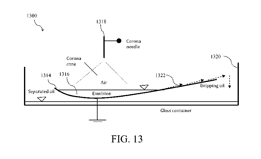
embodiments, the breakdown voltage of the gas in the corona discharge
embodiments discussed
CA 02907486 2015-09-16
WO 2014/172504 PCT/US2014/034432
26
herein can be adjusted by changing the gaseous temperature/pressure depending
on the elevation
of the plant site with respect to the sea level. When an electric potential
difference between a
sharp and blunt electrode is applied above a certain voltage, e.g., the so-
called corona discharge
threshold, the imposed electric field becomes strong enough around the sharp
tip such that the
surrounding neutral gaseous molecules in the electrode separation region
become partially
ionized. A cloud of ions is generated and accelerated toward the low potential
region. The
charge is transferred across the gap due to the drift of charge carriers
generated by the electric
field. Therefore, the corona discharge is accompanied by a weak electrical
current.
[00116] Corona discharge establishes a net and unipolar charge in the
emulsion. In some
embodiments, targeting the emulsion with unipolar ionic bombardment through
corona discharge
leads to separation of phases. For example, in some embodiments, one electrode
is immersed in
the emulsion, and the other corona discharge electrode is immersed in the air
or gaseous medium
above the emulsion interface. The gaseous medium may be at any temperature and
pressure.
[00117] In some embodiments, the emulsion can be a mixture of different
liquids, particles and
liquids, proteins and DNA, cells, or any matter within an insulating liquid or
dielectric liquid
with low electrical conductivity. In some embodiments, the corona electrode is
an electrode or
systems of electrodes with sharp tip or tips. The corona discharge emits from
the sharp tip or
tips. In some embodiments, the corona discharge electrode can be a needle,
multi-needles with
different arrangements, sharp blade or blades, thin wire or multi-wires, wires
coated with
microstructures, nano-tubes (CNT) or nano-structures or any other sharp
geometries. In some
embodiments, the corona discharge needle is helical, sawtooth, or any other
sharp point needle.
In some embodiments, the electrode is preferably constructed from materials
that are capable of
withstanding the ionization-induced corrosion, thereby minimizing maintenance
costs. In some
CA 02907486 2015-09-16
WO 2014/172504 PCT/US2014/034432
27
embodiments, the gaseous medium in which the corona electrode(s) is fixed can
be any gaseous
medium such as nitrogen, oxygen, air, argon, helium or any other gases or
combination of gases,
at any pressure or temperature. In some embodiments, the collector electrode,
which is
immersed in the emulsion, can be, for example, a metallic bare electrode, a
silicon substrate with
native oxide, a metallic electrode with dielectric thin film coating, or the
like. In some
embodiments, the geometry of the immersed electrode can be planar, a three-
dimensional
(contoured) surface, a wire or wires, or a mesh, for example. In some
embodiments, the
immersed electrode can have any geometry or shape.
[00118] In some embodiments, the potential difference between the corona
emitter electrode
and immersed electrode (which can be grounded or can be at different
potential) can be applied
by a high voltage power supply. In some embodiments, at and above a corona
discharge
threshold voltage, by slightly increasing the voltage, a small current can be
measured between
the electrodes across the gaseous gap and the emulsion. This is a non-limiting
example of a
signature of the corona discharge. Another non-limiting example of a
qualitative signature is an
acoustic noise generated by the discharge phenomenon, which is sometimes
accompanied by a
blue-violet glow around the sharp tips. In some embodiments, corona discharge
may or may not
accompany with this glow depending on humidity and other factors. Increasing
the voltage, one
may increase the current across the emulsion and increase the volume charge
density acquired by
emulsion, in accordance with some embodiments of the invention.
[00119] In some embodiments, as soon as corona discharge is established, the
size of the droplets
begins to grow. In some embodiments, the growth rate is such that after a
short period, large
droplets can be visually observed in the bulk emulsion. This is evidence of a
high rate of electro-
coalescence. Note that either positive or negative polarity can be applied to
the corona electrode.
CA 02907486 2015-09-16
WO 2014/172504 PCT/US2014/034432
28
Choosing positive polarity, however, may increase the electro-dynamic
stability of the discharge,
in accordance with some embodiments of the invention.
[00120] An important difference between previous techniques and the unipolar
techniques
described herein is that adjacent droplets in the emulsion acquire net and
unipolar charges.
Therefore, here, the separation is based on strong coulombic force between
charged droplets.
For example, applying positive corona discharge results in droplets with
positive charge, while
applying negative corona discharge results in droplets in the emulsion with
negative charge. The
sharp electrode(s) is/are separated from the emulsion interface, and there is
no electrical contact
between the emulsion interface and the sharp emitter electrode, in accordance
with some
embodiments of the invention. Therefore, only a single polarity electrode is
required to be in
physical contact with the emulsion, in accordance with some embodiments of the
invention.
Having only one polarity inside the emulsion is advantageous, in accordance
with some
embodiments of the invention. In some embodiments, this may significantly
reduce the chance
of electrostatic events, particularly because the main voltage drop occurs
across the
gaseous gap, not within the emulsion. Moreover, the amount of charge injected
into the
emulsion is independent of oil breakdown strengths because the electrode has
no ohmic contact
with the emulsion, and a large volume of charge may be locally injected into
the emulsion. This
leads to further non-uniformity in the field and an increase in the incidence
rate of droplet
coalescence.
[00121] Furthermore, in some embodiments, the method can be effective even
with highly
conductive emulsions (e.g., where salt concentrations in the aqueous phase are
high), since the
charge is generated outside of the emulsion. Thus, in some embodiments, the
amount of current
is primarily dictated by discharge properties in the gaseous gap and is less
dependent on the
CA 02907486 2015-09-16
WO 2014/172504 PCT/US2014/034432
29
emulsion. Therefore, the embodiments discussed herein can be adapted to any
oil-water mixture
with any quality of oil or water. It should be noted that the content of salt
in water is also not
important for achieving successful results and desired coalescence levels.
[00122] In some embodiments, coalescence of droplets of salt water solution of
high salt
content (e.g., > 0.5 M,> 1.0 M,> 1.5 M, or > 2 M) can be observed in an
emulsion with
silicon oil. Conventional electro-coalescencers are designed specifically for
quality of
oil/water based on oil/water and the salt contents ¨ and these can vary region
to region. However,
using some embodiments described herein, one can control both applied voltage
and current by
changing the pressure of the gaseous medium, increasing the voltage at the
source, and/or varying
the time of corona exposure to adapt the technique for a desired separation
output with oil/water
emulsions having different qualities (e.g., different salt contents). The
process is easily adapted
and controlled for application to a wide variety of emulsion compositions and
separation needs.
[00123] Without wishing to be bound by a particular theory, the mechanism of
unipolar
separation appears to follow a newly-discovered phenomenon of attraction
between like-charges
in an insulating medium. It has been speculated that like-charge particles may
attract; however,
it has remained an outstanding question.
[00124] Two charged conducting hard spheres almost always attract each other
if they are
close enough. See Lekner, John, "Electrostatics of two charged conducting
spheres," Proceedings
of the Royal Society A: Mathematical, Physical and Engineering Science
468.2145 (2012): 2829-
2848, incorporated herein by reference in its entirety. Attractive force
arises due to the mutual
polarization of spheres and redistribution of the surface charge density over
one of these spheres.
As two positively charged spheres approach closer, one gets a negative charge
density at the pole
closest to the other sphere, and then the other acquires an increased positive
charge density at its
CA 02907486 2015-09-16
WO 2014/172504 PCT/US2014/034432
neighboring pole. This attractive force increases without limit as two spheres
are approaching
together. The localized attraction of near charges wins over the overall
repulsion of coulombic
force between the two like-charge spheres, and they attract each other. One
theoretical exception
to the principle discussed above is when the two spheres have the same charge
ratio that they
would obtain by being brought into contact. In this case, two spheres repel.
Presented herein are
applications of this principal in the coalescence of like-charged droplets
having different charge
ratio for separation of phases of an emulsion, as evidenced by experimental
results presented
herein.
Experimental Set-up and Examples
Direct ion injection ¨ corona discharge
[00125] FIG. 1 is a schematic drawing demonstrating corona discharge of
positive or negative
ions targeting an emulsion interface to promote coalescence of droplets, in
accordance with some
embodiments of the invention. The schematic 100 on the left shows a schematic
drawing of the
emulsion 102 with a number of droplets 104 dispersed throughout the emulsion
102 prior to
applying a voltage. The schematic 100' on the right shows a schematic drawing
of the emulsion
102' after applying the voltage ¨ as seen in this schematic, at least some of
the droplets 104
coalesced forming larger droplets 104'. The ionic bombardment due to the
corona discharge
may directly inject the created ions into the emulsion volume from the
interface. The
electrification of the emulsion occurs from an external source (corona
discharge). The ions are
generated outside of the emulsion and are directly injected into the volume
from the emulsion/air
CA 02907486 2015-09-16
WO 2014/172504 PCT/US2014/034432
31
interface. The ions distribute in the emulsion and droplets acquire net charge
but with the same
polarity. Corona discharge creates highly non-uniform single polarity charges
in the emulsion.
Without wishing to be bound to any given theory, it is believed that the
difference of charge
between adjacent droplets causes attraction and eventual merging of droplets.
By increasing the
time of exposure, the oil can be separated from water by coalescing the small
water droplets and
growing the droplet sizes.
[00126] FIG. 2 is a schematic drawing showing a corona discharge system for
separation of
two or more phases of an emulsion to simultaneously promote droplet
coalescence and pumping
effect or differential spreading phenomenon for phase separation, in
accordance with some
embodiments of the invention. The schematic 200 on the left is a schematic
drawing of an
emulsion 202 with a number of droplets 204 dispersed throughout the emulsion
202 prior to
application of corona discharge. The schematic 200' on the right is a
schematic drawing of an
emulsion 202' after applying corona discharge to the emulsion, which caused at
least some of the
droplets 204 to coalesce and form larger droplets 204'.
[00127] In some embodiments, the corona discharge electrode system may be
designed so
that it takes advantage of both (i) the separation of water droplets (or other
phases) out of the
emulsion due to like-charge electro-coalescence, and (ii) the physical
pumping/spreading/moving
of the oil-rich phase away from the water-rich phase (or other remaining
phase), e.g., out of the
emulsion container. Because the 'pumping' or spreading effect occurs with oil
and not with
water, the differential effect can be exploited for further separation
efficiency, in accordance with
some embodiments of the invention.
[00128] In one embodiment, a tank of emulsion is equipped with a protruding
edge (ramp) which
serves as a low voltage electrode. A sharp electrode is positioned above the
tank and is used to
CA 02907486 2015-09-16
WO 2014/172504 PCT/US2014/034432
32
establish the corona discharge. Emulsion may be added to the taffl( in a
continuous, semi-
continuous, or batch-wise manner. The corona discharge from a single or
multiple electrode may
physically move or pump the purified oil phase up the ramp and direct it to
another container or
conduit for retaining the purified oil separated from the emulsion. The
separated aqueous phase
may remain in the bottom of the tank where it can be drained.
[00129] In some embodiments, one or more of the corona discharge emitter
electrodes are
placed around the ramp to exploit the corona discharge pumping effect. While
electro--
coalescence is occurring inside the bull(, the purified oil is pumped up by an
appropriate
configuration of electrodes. A higher salt content in the aqueous phase of the
emulsion may even
be favorable here, since it may enhance the contrasting electrical
conductivities between the oil
phase and the aqueous phase, in accordance with some embodiments of the
invention.
Unipolar charge transfer by mass transfer ¨ spraying unipolar charged droplets
into the emulsion
[00130] In corona discharge embodiments, the charge is introduced directly by
ionization of
gaseous molecules. However, one may deliver unipolar charges into the bulk
emulsion via a
charged mass. For example, spraying unipolar charged drops, or a stream, into
an emulsion may
result in the emulsion acquiring a net and unipolar charge such that adjacent
droplets therein
acquire net and unipolar charges. In some embodiments, spraying takes place
via
electro -spraying or mechanical spraying (e.g., atomization).
[00131] FIG. 3 is a schematic illustrating a system for spraying unipolar
charged droplets 306
into an emulsion 302 for separation of the emulsion phases, in accordance with
some
embodiments of the invention. The schematic 300 on the left shows the emulsion
302 with a
CA 02907486 2015-09-16
WO 2014/172504 PCT/US2014/034432
33
number of droplets 304 dispersed throughout the emulsion 302 prior to electro-
spraying. The
schematic 300' on the right shows the emulsion 302' after electro-spraying,
which caused at least
some of the droplets 304 to coalesce forming larger droplets 304'.
[00132] FIG. 3 is a schematic showing a system for spraying unipolar charged
drops into
an emulsion for separation of the emulsion phases. In some embodiments,
electrostatic
atomization of insulating oil or water may be used and the cloud of small,
charged droplets may
be directed into the emulsion. In some embodiments, the injected atomized
liquid may be chosen
based on composition of the emulsion to be separated. For example, for a water-
in-oil emulsion,
where water is the dominant phase, in some embodiments, oil can be atomized.
In some
embodiments, the liquid droplet with unipolar net charge in the emulsion may
transfer the charge
through a conduction and/or convection mechanism to the emulsion. The native
water droplets
in oil acquire these charges, and the mechanism as discussed with corona
discharge can occur and
cause the electro-coalescence of unipolar charged droplets. Different
configurations of
electrodes can be used; for example, circular nozzles, rectangular atomizers,
single- or multiple-
atomizers can be used.
Pouring bath of unipolar charged liquid into emulsion
[00133] In another non-limiting embodiment of unipolar charge transfer via
mass transfer, an
amount of the emulsion is charged first then introduced into a larger quantity
of the emulsion.
For example, corona discharge can be used in some embodiments to inject charge
into a bath
including a portion of the emulsion. Then, the bath of charged liquid or
mixture is introduced into
a larger batch or stream of the emulsion where separation is performed. The
charged liquid
CA 02907486 2015-09-16
WO 2014/172504 PCT/US2014/034432
34
diffuses into the emulsion and transfers charge by both conduction and
convection. Unipolar
charge transferred by mass transport and electric conduction may cause
coalescence of droplets in
the bulk so that the droplet size of the dispersed phase grows. The separated
droplets are large
enough to sediment and collect in the bottom of the batch. This method can be
combined with
gravitational separation to expedite the separation process. Pure oil can be
charged and pour into
the gravitational separator tanks. The unipolar electro-coalescence occurs due
to the unipolar
separation.
Tribo-electrification: unipolar separation technique
[00134] In some embodiments, tribo-electrification is used to perform unipolar
emulsion
separation. This method is an alternative to corona discharge exposure and
spraying of unipolar
charged droplets into an emulsion. It is as simple as the corona discharge
technique, but it may
eliminate the need for an active power supply, in accordance with some
embodiments of the
invention.
[00135] For example, in some embodiments, a charge is transferred into an
emulsion by passing
it through a polymer pipe made from PMMA or other tribo-electric material. In
some
embodiments, the pipe interior surface may be coated with a polymer or a
combination of
polymers such as PMMA, PVC, or the like. Passing the emulsion over the surface
may create a
unipolar volume charge inside the emulsion due to the friction between the
pipe and the emulsion.
This unipolar charge may result in an increased droplet size due to unipolar
electro-coalescence.
For example, in some embodiments, this concept can be applied to gravitational
towers where
increasing the size of water droplets may cause significantly faster
separation. In some
CA 02907486 2015-09-16
WO 2014/172504 PCT/US2014/034432
embodiments, it may be sufficient to simply pass the emulsion over a proper
tribo-electric
material so that the droplets become charged. In some embodiments, the
gravitational tower,
separation column, or other container should be electrically insulated so that
the charge remains
in the separator.
Observations
[00136] Methods described herein may be combined with current oil/water
separation processes
without substantial changes in their layouts. Existing systems may be
retrofitted with a unipolar
charge separation stage or module, for example, as described herein.
[00137] Demonstrated herein are new separation techniques in which unipolar
droplets attract
each other. Unlike previous dielectrophoretic techniques, here the active
mechanism is
electrophoretic force. Experiments verify the like-charge attraction of
dispersed droplets in a
background phase. This attraction causes coalescence of droplets, thereby
affecting separation of
phases of the emulsion. The concept can be applied to separate droplets in
emulsions, as well as
solid particles in suspensions. The applications include, but are not limited
to, separation of
water/oil emulsions, as well as separation of cells, proteins, DNA, and other
kinds of mixtures.
[00138] In certain embodiments, only the collector electrode(s) is/are
immersed into the
emulsion/mixture, and the emitter electrode is outside the emulsion/mixture.
In certain
embodiments, the mixture acquires a net charge. Therefore, unlike the
conventional method
where volume charge is negligible, in our method, volume charge is essential,
and in certain
embodiments it is as at least 1nC/m3, at least 10 nC/m3, at least 100 nC/m3,
or at least 1 C/m3.
[00139] An advantage of methods presented herein is that the high voltage
electrode has no
CA 02907486 2015-09-16
WO 2014/172504 PCT/US2014/034432
36
contact with the emulsion. Since the main voltage drop occurs across the gap,
the chance of arc
or electrostatic breakdown can be significantly reduced. Moreover, in the
embodiments involving spraying unipolar charged droplets into the emulsion or
tribo-
electrification of the emulsion, the probability of electrostatic breakdown is
significantly reduced
while maintaining unipolar charge in the bulk.
[00140] Another advantage of the proposed method using corona discharge is
that large volume
charge densities can be injected into the emulsion so that there is strong non-
uniformity of the
electric field in the non-homogenous emulsion medium. This non-homogeneity in
the field may
cause potential difference between like-charge droplets and this may increase
the chance of
coalescence. Moreover, in some embodiments, physical separation of water/oil
emulsion phases
is enhanced by corona discharge because the purified oil is pumped (or pumping
is assisted) by
the electrostatic pressure while the electrostatic pressure on the conductive
aqueous phase is zero.
This can be a particularly important embodiment for separation of a mixture in
a micro-gravity
condition, for example, where power is limited and a gravitational field is
absent. Gravitational
separation cannot be used in micro-gravity, while corona discharge embodiments
can be a
replacement of such methods. Enhanced coalescence rate along with a pumping
oil phase may
result in generation of larger water droplets with lower oil contaminations
with minimal power
consumption, even in outer space applications.
[00141] Electro-coalescence does not appear to depend on orientation of
droplets with respect to
the electric field in the embodiments described herein. In conventional
methods, droplets must
be oriented in the field so that attractive force is generated. In those
electro-coalescers, small
deviation of the droplet may cause repulsion between droplets and
stabilization rather than the
desired separation. In contrast, in the embodiments described herein, electro-
coalescence is
CA 02907486 2015-09-16
WO 2014/172504 PCT/US2014/034432
37
omni-directional. Direction and orientation is not a requirement since the
electrophoretic force
can be exerted in any direction.
[00142] Experiments show the effectiveness of the corona discharge systems
described herein for
both water-in-oil emulsions and oil-in-water emulsions. In certain
embodiments, phases of
emulsions with average droplet size < 50 microns, <25 microns, < 10 microns, <
1 micron, <0.5
micron or < 0.1 micron can be separated. In certain embodiments, the range of
applied voltage
can be from about 1 to about 20 kilovolts (e.g., a few kilovolts) while the
gap spacing between the
electrode and interface of emulsion can be from about 0.1 mm to about 50 mm
(e.g., on the order
of tens of millimeters). In some embodiments, the applied voltage and the gap
can be varied in
larger ranges than presented above, but the resulting field should be large
enough (-105-107
Vim) to cause corona discharge from the tip of corona electrode. "Peek's law"
may provide a
first approximation of applied potential for a given gap spacing and a given
gaseous pressure and
temperature, but the potential also depends on the radii of curvature of the
corona tip. The
corona current and number of corona tips may vary depending on geometry and
number of tips,
but for a single tip the corona current is in the range of about 0.1 to about
200 microamp.
Increasing the time of exposure may cause enhanced purification, but as little
as 1 to 30 seconds
is sufficient to produce satisfactory coalescence in certain embodiments. The
corona discharge
separation can also be conducted in multiple stages. At each stage, one may
use different corona
voltages with different configurations. However, one stage of exposure might
be enough.
[00143] In certain embodiments, the container for the emulsion, itself, (or a
portion thereof)
serves as grounded electrode, and can have different shapes. It can be a flat
electrode, an
inclined flat electrode, a contoured electrode, or a curved electrode, for
example. The emulsion
can be stagnant or it may flow in an open channel.
CA 02907486 2015-09-16
WO 2014/172504 PCT/US2014/034432
38
[00144] The electrophoretic forces can collect the purified oil directly or it
can be a dead-end
system. The corona discharge exposure can be performed as a pre-treatment step
for use in an
existing system (e.g., a retrofit of a gravitational and/or sedimentation
emulsion separation
process), or it can be easily combined with other techniques. For example, the
corona discharge
exposure may promote coalescence between small droplets to form larger
droplets, which are then
more easily handled by current separation systems (e.g., gravitational,
sedimentation, and/or
chemical additive separation processes).
[00145] In some embodiments, the methods disclosed above can be combined with
each other if
required. In some embodiments, these methods can be combined with other
traditional
techniques, electrostatic existing techniques, gravitational, filtration or
other techniques as pre-
steps or post-process steps depending on required quality of the output
purified phase and
background.
[00146] In some embodiments, in order to increase the safety to a required
degree, one may
replace the gaseous phase with any other gases, for example, inert gasses. The
technique is not
limited to any particular pressure or temperature of the gas or emulsion,
allowing for a more
versatile separation process.
[00147] In some embodiments, the method may be applied to cause coagulation of
solid particles,
such as mud, sand, or the like in petroleum or in a biological medium.
Similarly, coagulation can
be achieved for cells, proteins, DNA, or RNA coagulation (or coagulation of
other genetic
material) by unipolar charging of a mixture containing such components.
CA 02907486 2015-09-16
WO 2014/172504 PCT/US2014/034432
39
Coalescence of like-charged droplets
[00148] FIG. 4A shows a series of micrographs of two droplets of deionized
water in silicon oil
obtained at various times in relation to contact (t = 0) of the two like-
charged (positively
charged) droplets. Qa is the charge of droplet a, Qb is the charge of droplet
b, ra is the radius of
droplet a and rb is the radius of droplet b. Attraction of droplets and
coalescence is observed
where the charge densities of the droplets are different, e.g., for example
where Qa/ra >> Qb/rb,
and where the droplets are sufficiently close to each other.
[00149] FIG. 4B presents the experimental results for electrostatic
interaction between two
positively charged isolated metal spheres of the same size at close
separations. It was observed
that the positively charged spheres attract each other when the difference in
magnitude of the
charge between the spheres is large enough. As the charge difference is
established, the
attractive force pulls the right sphere towards the fixed sphere on the left.
After a brief contact,
the two spheres become equipotential and then repel each other. This
observation confirms a
recent prediction for attraction of conductive hard spheres carrying like-
charges and the
repulsion after the contact.
[00150] FIG. 4C shows a series of micrographs of electrostatic interaction of
like-charge water
droplets of different size carrying positive charges in a bath of oil with
sufficiently large charge
differences. The charges at the top and bottom droplets were +10.7 pC and 0.94
pC, respectively.
Similar to metal spheres discussed in relation to FIG. 4B, two non-
equipotential droplets with a
large enough charge difference attract at close separations. However, after
the contact at t = 0,
unlike the metal spheres of FIG. 4B, two droplets attract each other and
coalesce as shown in
FIG. 4C. Like-charge droplets slowly approach, and coalescence occurs
immediately after the
CA 02907486 2015-09-16
WO 2014/172504 PCT/US2014/034432
apparent contact at the nearest poles. The scale bar shown in FIG. 4C is 0.5
mm. The background
oil is 450 centistokes silicone oil.
[00151] FIG. 5 presents experimental data showing that coalescence of two like-
charged
droplets occurs when Coulombic force (FAtr/FRep) is roughly > 1. Where the
magnitude of the
difference in like charges between the two droplets is greater (e.g., where
Qa/Qb is higher),
coalescence is observed between droplets at greater distances from each other,
up to about lmm
apart.
[00152] FIG. 6A depicts the result of charge measurements for two positively
charged near
droplets of the same size at a fixed initial separation of 50 lam. The initial
separation is the gap
between the neutral droplets before charging. As it is shown in FIG. 6A, a
small charge
difference between droplets is enough to cause electro-coalescence of droplets
according to some
embodiments of the invention.
[00153] In contrast, FIG. 6B illustrates that for two electrically
connected identical water
droplets, it is observed in some embodiments that droplets do not merge even
if they are
mechanically pushed together. This is attributed to the fact that the droplets
become
equipotential upon contact and the charge difference then equals zero. For
identical spheres,
a=b, the expression for the short-range attractive force between like-charge
conductive spheres
with net positive charges of Qa and Qb was obtained as
tQa Qb.12
Atr =
8¨gnn ly
L s)
(2)
Co, S and y are medium permittivity, the separation between droplets and
Euler's constant,
respectively. From Eq.(2) above, it can be inferred that close enough spheres
of the same size
CA 02907486 2015-09-16
WO 2014/172504 PCT/US2014/034432
41
always attract if and only if Qa # Qb. Whereas, for two identical spheres with
precisely the same
charges, a = b and Qa = Qb, the attractive force is zero. In this case,
equally charged spheres
become equipotential and repel. For equipotential spheres at close
separations, the repulsive
force, Frep, is independent of the separation and can be obtained by Kelvin's
formula:
(ki 4 In 2 ¨
F = _______________________________
47E0 (2a)2 61n2)2
(3)
[00154] Although the experimental results shown in FIGs. 6A, 6B, and 6C can be
interpreted by
the expression for attraction of like-charge presented in Eq.(2) above, it is
still not clear why the
unequally charged droplets coalesce after contact. In order to investigate the
mechanism of
coalescence, a high-resolution high speed imaging of droplet coalescence was
performed
immediately before and after contact.
[00155] FIGs. 7A-7C show a mechanism that occurs upon coalescence of two like-
charged
droplets in an emulsion. At t = 20 microseconds, an electrostatic bridge
appears, and, without
wishing to be bound to any particular theory, appears to thicken into a
capillary bridge, resulting
in coalescence of the droplets.
[00156] FIGs. 8A, 8B, and 8C illustrate the behavior of like-charge DI water
droplets in silicone
oil in a series of sequential high-speed images at 180,000 frames s-1. For two
neighboring like-
charge droplets, the droplet with larger absolute positive charge (top
droplet) polarizes the other
droplet with smaller net positive charge (bottom droplet). FIG. 8D represents
a cartoon of
electrostatic interactions for attraction and coalescence of like-charge
droplets. The cartoon is
based on experimental visualizations presented in FIGs. 8A-8C.
[00157] As shown in FIG. 8D, the batch of negative image charge (gray cloud)
appears at the
nearest pole of the droplet with smaller positive charge (pink cloud). The
electric field between
CA 02907486 2015-09-16
WO 2014/172504 PCT/US2014/034432
42
poles of nearby droplets increases as a result of local charge redistribution.
The attraction
between the positively charged meniscus and its negative image charge on the
nearest pole of the
other droplet meniscus causes attraction between droplets.
[00158] As can be seen in FIGs. 8A, 8B and 8C the attractive force induces
Taylor cone-like
deformation due to local enhancement of Maxwell stresses in the nearest poles
where the electric
field is strong. Both droplets and the two deformed meniscuses approach
together. As the two
meniscuses approach, the electric field becomes even stronger, and the
enhanced field
redistributes the charge and its image causing more pronounced deformations in
the meniscuses.
The deformed meniscuses finally touch each other, and a liquid bridge is
immediately formed
between the two droplets.
[00159] For droplets with small separations as presented in FIG. 8A, the
formation of the
bridge immediately after contact leads to high local curvature of the neck
between connecting
like-charge drops. The formation of the curved neck creates a local low-
pressure region
resulting in an inward flow towards the bridge. The inward flow supplies
liquid to the bridge
and fattens the neck; thus, the coalescence of like-charge droplets proceeds.
For such small
separations, the bridge morphology at its early evolution, t=0, cannot be
captured with a proper
optical resolution due to its small sizes. In order to visualize the details
of evolution with
reasonable resolutions after the contact, the initial separation between the
droplets was increased
as can be seen in FIGs. 8B and 8C In order to establish the like charge
attraction and coalescence
for the new larger separations, the absolute magnitude of the charge and the
charge difference
between drops were increased. The charge on the top droplet was increased near
its Rayleigh
limit while the charge on the bottom droplet was kept small. For these larger
initial separations,
the electro-coalescence also happens. It was observed that the two droplets
attract each other and
CA 02907486 2015-09-16
WO 2014/172504 PCT/US2014/034432
43
their meniscuses are deformed at their nearest poles. As the two deformed
meniscuses contact, a
remarkably stable transient liquid bridge is formed. The high aspect ratio
liquid bridges clearly
differ from the conventional capillary bridges. Such transient liquid bridges
are reminiscent of
the previously reported floating water bridges in air and the electrically
supported high aspect
ratio columns of slightly conductive liquids. Similar to the water floating
bridge, since the
permittivity of the liquid bridge is larger than the permittivity of the
medium (oil in our case), Ew
> co, the current carrying liquid bridge is stabilized by the normal and
tangential electrostatic
Maxwell stresses in the bridge. Both electrostatic and polarization force
tends to "level" the
bridge against the destabilizing effects due to the surface. Such stable
liquid bridge holds two
droplets electrically connected. Initially, when the electric field across the
bridge is large, the
liquid bridge between two charged droplets is stabilized by the electric
field. As the charge
transfers across the bridge, the tangential field between oil/water interfaces
along the bridge
gradually decreases. Subsequently, the electrostatically supported bridge
reverts to capillary
bridge. A capillary bridge between connecting droplets tends to minimize the
surface of the
connecting bodies. The formation of a self-sustained current carrying bridge
and its
transformation to capillary bridge favor the coalescence of two connecting
droplets. For highly
charged neighboring droplets, before the meniscus contact, electro-spraying
occurs due to the
intense tangential stresses exerted to the deformed pole. Even in the presence
of such cone-
jetting and electro-spraying between highly charged droplets, the like-charge
coalescence
proceeds. This implies that coalescence of like-charges is a general
phenomenon and it may
happen for wide ranges of charge magnitudes.
[00160] FIGs. 9 and 10 show two example schematics of oil/water emulsion
separation systems
that employ like-charged droplet coalescence as described herein.
CA 02907486 2015-09-16
WO 2014/172504 PCT/US2014/034432
44
[00161] In FIG. 9, an emulsion flows in a half pipe 902 below a corona wire
(emitter electrode)
904. In some embodiments,. the half pipe 902 may contain or may itself be a
grounded collector
electrode. The separation occurs during flowing of the emulsion along the half
pipe 902.
Differential spreading/pumping of the oil phase as a result of corona
discharge forces the oil
phase over the edge of the half pipe 902, and down a collector ramp 906 into a
collection vessel
908. Instead of a half pipe 902, another channel of different geometry could
be used, for
example. In certain embodiments, multi-branch half pipes can be used, equipped
with corona
wires above the emulsion/air interface.
[00162] In the embodiment shown in FIG. 10, an emulsion fills a tank 1010. A
corona wire
1004, corona blade, or any other type of sharp emitter electrode is placed
above the tank near a
ramped or tilted side or lip 1012 of the tank 1010. Differential
spreading/pumping of the purified
oil phase results from the corona discharge and forces the oil phase (and not
the water phase) over
the lip and into a collection vessel 1008. In some embodiments, the tank may
be filled constantly
with emulsion while corona discharge separates the phases and the pure oil is
collected.
Alternatively, in some embodiments, the tank may operate in batch mode or semi-
batch mode.
For large scale systems, in some embodiments, multiple high voltage electrodes
can be used.
[00163] In some embodiments, tribo-electrification is used instead of corona
discharge to
produce the unipolar conditions leading to separation of the phases of the
emulsion.
[00164] The concept of like-charge coalescence can be applied to the
destabilization of
emulsions. FIGs. 11A, 11B and 11C demonstrate like-charge coalescence for a
system of two
water drops in oil and a water-in-oil emulsion. FIGs. 11A and 11B show the
unipolar
coalescence of systems of two and three neighboring water drops in oil
subjected to unipolar ion
injection, respectively. A positive DC corona discharge was established by
applying high
CA 02907486 2015-09-16
WO 2014/172504 PCT/US2014/034432
voltages above the corona discharge thresholds to a sharp emitter electrode.
The air adjacent to
the emitter electrode was ionized, and a cloud of positive ions was
accelerated towards the
air/liquid interface due to the strong electric field. The accelerated
positive ions were injected
into the oil volume. The injected charge was deposited over the surface of the
water/oil droplet
interface. Since the acquired net charge by the water droplets was
proportional to their surface
areas, an arbitrary charge difference between two neighboring droplets with
different size may be
established by applying non-uniform charge injection. Once enough of a charge
difference is
established, short-range attraction may cause coalescence of like-charge water
drops.
[00165] FIG. 11C shows like-charge coalescence and unipolar separation of an
emulsion
comprised of 1.5% wt. DI water in Hexadecane subjected to a corona discharge
with different
exposure times. In order to stabilize the emulsion, 1.6% wt. Surfactant Span80
was added. The
mean diameter of droplets in emulsion was measured to be about 300 nm right
before the ionic
exposure. The 20 ml of the emulsion poured in two identical beakers. The left
beaker was
exposed to a corona discharge while the right beaker was left with no
exposure. Continuous
exposure of the emulsion to the discharge supplies spatially non-uniform
volume charge density
to the adjacent water droplets. The adjacent water droplets acquire non-
uniform positive charge,
which promotes like-charge coalescence of water droplets in oil. As a result,
the size of the
droplets increased as they were exposed to the discharge and the emulsion
separation occurred.
As shown in FIG. 11C, the cloudy emulsion in the left beaker turned to
transparent oil as the
water droplets were coalesced and settled down. In the absence of exposure,
the cloudy
appearance of the right beaker showed negligible change during the same time
of experiments
suggesting that the coalescence of droplets was minimal as the emulsion was
stable during the
experiments.
CA 02907486 2015-09-16
WO 2014/172504 PCT/US2014/034432
46
[00166] FIGs. 12A, 12B, and 12C show images of like-charged droplets in an
emulsion charged
by corona discharge, compared with charging by trio-electrification. In order
to obtain the tribo-
electrification results presented in FIG. 12C, PMMA substrate was rubbed with
polyester fiber.
Other pairs of materials can be used to produce the charged substrate onto
which the emulsion is
poured or otherwise introduced. Deposition of emulsion on un-rubbed substrates
produces no
separation effect since the charge is absent over the substrate. Upon rubbing
the dry PMMA
substrate, the substrate becomes positively charged while the fiber becomes
negative. The charge
over the substrate reached a saturation limit and was measured to be ¨100
nC/m2. Depositing the
emulsion on the charged substrate resulted in vigorous separation of the
emulsion. A small
charge difference between two neighboring droplets causes an attractive force,
which causes
coalescence of the water droplets. Small charge differences in a dense
emulsion may result in
destabilization of the emulsion and the desired separation of the phases.
These charges can be
unipolar on two or many droplets. Without wishing to be bound to any
particular theory, a single
polarity of charge is sufficient to induce emulsion separation.
Separation of 25% water-75% oil
[00167] In this example, corona discharge assisted separation of an emulsion
was conducted in
the presence of electrostatic pumping of the separated oil. As shown in FIG.
13, a curved
electrode 1314 was first filled with an emulsion of DI water in Silicone Oil
(25 wt.% water, 75
wt.% oil) 1316. The curved electrode 1314 was grounded. A corona needle 1318
was fixed
above the emulsion/air interface. The distance between the corona electrode
and emulsion
interface was tens of millimeters. Therefore, the grounded electrode 1314 had
contact with the
CA 02907486 2015-09-16
WO 2014/172504 PCT/US2014/034432
47
emulsion 1316 while the corona needle 1318 was located in ambient air and had
no ohmic
contact with the emulsion 1316. By applying voltage to the needle 1318 above a
critical value, a
positive corona discharge was established over surface of emulsion 1316 and
curved grounded
electrode 1314. The corona discharge establishment was confirmed by measuring
the corona
current.
[00168] The cloud of ionized air accelerated toward the emulsion 1316 in the
presence of the
strong electric field and the emulsion 1316 was positively charged with such
ionic bombardment.
The water droplets in the bulk oil immediately coalesced. Without wishing to
be bound to a
theory, non-uniform charging of the droplet is believed to be responsible for
coalescing of
positive-positive charged droplets. Moreover, the pure separated oil by corona
discharge
exposure climbed up the curved ramp on the right side of the curved grounded
electrode 1314.
Corona discharge was used to both separate and pump the pure oil out of the
emulsion container
1320. It should be noted that only pure oil could climb up the ramp 1322,
while water was not
affected. Systems that exploit this differential effect may be implemented,
further enhancing
separation of phases of the emulsion. The electrostatic pressure cannot be
developed over a
water droplet, and water (or other aqueous phase) cannot move up the ramp
1322. This is
believed to be because the electrical conductivity of water is too high, and
the charge relaxation
is fast. Therefore, the electrostatic pressure cannot be established over
water droplets and pump
them up. In contrast, for background oil, charge may stay for a long period of
time and electric
pressure can be established and pump the separated pure oil up the ramp.
[00169] Corona discharge of 7 kV-1 A was applied (7 milliwatt power
consumption) for about
seconds over the air-emulsion interface to the water-in oil emulsion as can be
seen FIG. 14A.
FIG. 14B illustrates that the small droplets showed vigorous electro-
coalescence. About 90% of
CA 02907486 2015-09-16
WO 2014/172504 PCT/US2014/034432
48
the oil content was recovered at this stage. The recovered oil was clear but
with minor tracks of
water micro-droplets. The purified oil with minor track of water droplets was
transferred to the
third stage. With 20 seconds of sequential discharge 7 kV-1 A and then
stronger discharge 8.6
kV-2 A and much stronger 12 kV- 3 A, the accomplished separation shows a
separation of
99.9%. The energy consumption for corona discharge-assisted separator with a
single needle
electrode can be as low as a few miliwatts for lab-size separations. In many
embodiments,
methods and systems described herein can be used to scale up. For example,
with only 40 watt
hours (10 kV, 1 A), one may process 0.1 m3 per /hour.
[00170] FIG. 15C illustrates an emulsion used for the separation process. FIG.
15B shows
silicone oil recovered from the emulsion electrostatically. FIG. 15A
illustrates water after
corona discharge-assisted recovery.
Separation of 90% water-10% oil
[00171] Setup 1600 shown in FIG. 16 demonstrated corona discharge separation
of the emulsion
without exploiting the pumping effect. The corona discharge-assisted technique
can be used to
separate water out of predominately-oil emulsions, where the emulsion contains
low
concentrations of water and/or small droplet sizes of water emulsified in the
oil background. In
other embodiments, the corona discharge-assisted technique can be used to
separate water and oil
phases from emulsions that are predominately water.
[00172] The corona discharge exposed emulsion tends to minimize its
electrostatic energy when
exposed to the discharge. Therefore, the ions may transfer the oil droplet
towards the substrate.
If the substrate is oleophilic, the oil creates a thin film below the liquid
volume. The divergent
CA 02907486 2015-09-16
WO 2014/172504 PCT/US2014/034432
49
electric field may drag the oil out of the droplet and cause the water to
become separated. It
should be noted that when the oil is emulsified in water, the capacitance of
the system is large.
The charged oil layers are far from the low potential substrate. As the field
is exposed, the cloud
of ions reaches the water interface and passes through the interface. The oil
droplets are now
attracted to the substrate to make the capacitance as low as possible. The
corona discharge-
assisted technique makes separation possible even for emulsions with a
fraction of 1% oil in the
water. The technique shows promise, particularly where the substrate is flat.
The technique
seems to be more efficient when implemented in droplet-wise form.
Ion injection
[00173] In the configuration depicted in FIG. 17, the droplets 1730 are
directly charged in a
bath of emulsion by unipolar ion injection through a corona needle 1718
similar to the
embodiment shown in FIG. 13. However, because the container 1720 is not
curved, the oil
cannot be pumped up. The separated oil stays on the top and is not pumped out
by corona
discharge. After coalescence, the phases may be separated using standard
processes.
[00174] In one example, a quartz container was used. The quartz container was
filled with the
emulsion (10% oil-90% emulsion stabilized by Span 80 nonionic surfactant). A
grounded flat
electrode 1714 was fixed at the bottom of the container 1720 as shown in FIG.
17. A corona
needle 1718 was fixed above the emulsion/air interface. The gap between the
electrode and
emulsion/air interface was about 5 mm. The grounded electrode 1714 was a
silicon substrate
with a native oxide. By increasing the applied voltage, the electric current
across the emulsion
remained zero and emulsion did not destabilize. Further increasing the applied
voltage, at and
CA 02907486 2015-09-16
WO 2014/172504 PCT/US2014/034432
above the onset of corona discharge threshold, the current was established.
This is the signature
of the corona discharge. Above this threshold voltage, immediate coalescence
between water
droplets 1730 was observed, and phase separation (emulsion destabilization)
took place. In this
example, 7kV was applied and the total current at this voltage was 0.9 A. The
mean diameter
of water droplets 1730 in oil before separation was 50 gm. After corona
discharge exposure,
depending on exposure time, the mean droplet size grew an order of magnitude
larger.
Constructive Example ¨ Charging a Portion of Emulsion and Mixing Charged
Portion with
Neutral Emulsion
[00175] As shown in FIG. 18, a water in oil emulsion is split up between two
containers (or
the emulsion or other mixture may initially be present in two containers). A
first portion of the
emulsion or other mixture is placed into a container 1820. The emulsion 1816
is charged by
corona discharge. A corona needle 1818 and a grounded electrode 1814 with
dielectric coating
are used to establish the corona discharge, as discussed in some embodiments
above. The
grounded electrode 1814 is in contact with the emulsion 1816. A gaseous medium
(e.g., one gas
or a mixture of gases discussed above, at any pressure and temperature) is
located between the
emulsion 1816 and the corona needle 1818. When an electric potential
difference between the
corona needle 1818 and the grounded electrode 1814 is applied (e.g., by
continuous AC or DC
discharge or pulsed discharge) above a corona discharge threshold, the imposed
electric field
becomes strong enough around the sharp tip of the corona needle 1818. such
that the surrounding
neutral gaseous medium in the electrode separation region become partially
ionized, creating a
cloud of positive ions 1840, which charges the emulsion 1816. The charged
emulsion 1816' is
CA 02907486 2015-09-16
WO 2014/172504 PCT/US2014/034432
51
then transported via a conduit 1842 to a second container 1844. The second
container includes
initially neutral emulsion 1846. The charged emulsion 1816' may then be mixed
with the
initially neutral emulsion 1846 that needs to be separated.
Constructive Example ¨ Experimental Setups Using Different Emitter Electrode
and Grounded
Electrode Configurations
[00176] Referring now to FIG. 19, the experimental setup 1900 employs multiple
emitter
electrodes 1918 and a grounded electrode with dielectric coating 1914. The
experimental setup
1900' employs multiple emitter electrodes 1918 and a bare grounded electrode
1914'. The
experimental setup 1901 employs a single wire emitter electrode 1918' and a
grounded electrode
with dielectric coating 1914. The experimental setup 1901' employs a single
wire emitter
electrode 1918' and a bare grounded electrode 1914'.
Constructive Example ¨ Experimental Setups Applying Corona Discharge During
Transport of
an Emulsion or Other Mixture
[00177] Referring now to FIG. 20, experimental setups 2000 and 2001 are
illustrated.
Experimental setup 2000 illustrates applying corona discharge during transport
of a water in oil
emulsion 2016 (other mixtures may be separated as well). A corona discharge
wire 2018' is
placed above the emulsion 2016 (e.g., the corona discharge wire 2018 is not in
contact with the
emulsion 2016). In some embodiments, the corona discharge wire 2018' is
coated. In some
embodiments, the corona discharge wire 2018' is bare. Half (or another
suitable portion of the
CA 02907486 2015-09-16
WO 2014/172504 PCT/US2014/034432
52
pipe volume) is filled with gas (e.g., air or any gas composition that may
effectively increase the
effect of current discharge). The experimental setup 2000 allows for an
emulsion 2016 (or
another mixture) to be separated during transport using corona discharge. Any
suitable corona
discharge electrode geometries may be used.
[00178] Experimental setup 2001 illustrates applying corona discharge during
transport of a
water in oil emulsion 2016' (other mixtures may be separated as well).
Multiple corona
electrodes 2018 are placed above the emulsion 2016'. Half (or another suitable
portion of the
pipe volume) is filled with gas (e.g., air or any gas composition, including
mixtures of different
gases, that may effectively increase the effect of current discharge). The
experimental setup
2001 allows for an emulsion 2016' (or another mixture) to be separated during
transport. Any
suitable corona discharge electrode geometries may be used.
Constructive Example ¨ Tribo-Electrification Charging Exemplary Setup
[00179] Referring now to FIG. 21, an experimental setup 2100 for separating an
emulsion or
another mixture during transport is shown. Charge can be introduced to the
moving emulsion
2116 by tribo-electrification charging during transport. As shown in FIG. 21,
an emulsion 2116
may be separated during transport in a pipe 2150 (or any other conduit capable
of transporting an
emulsion or another mixture). The interior surface of the pipe 2148 (e.g., the
surface that is in
contact with the emulsion or other mixture being transported) is coated with a
tribo-electric
coating that is configured to improve tribo-electrification charging. In some
embodiments, the
coating 2150 includes a combination of Teflon and Nylon (in suitable
proportions). In some
embodiments, the coating 2150 is a static coating of a suitable type (e.g.,
suitable for improving
CA 02907486 2015-09-16
WO 2014/172504 PCT/US2014/034432
53
tribo-electrification charging). Unipolar charge in the volume of the mixture
can promote the
separation of the emulsion 2116 during the transport as it passes through the
pipe 2150.
Unipolar separation can be completed completely or in part during the
transport of the emulsion
through the pipe 2150.
Constructive Example ¨ Ionized Gas Exemplary Setup
[00180] Referring now to FIG. 22, an experimental setup 2200 for separating
emulsions or
other mixtures is shown. Neutral gas (e.g., gas having no net charge) 2254 is
fed into an
ionization chamber 2256. The neutral gas 2254 is then ionized in the
ionization chamber 2256.
In some embodiments, the neutral gas 2254 is ionized by using corona discharge
(e.g., as
discussed for other corona discharge embodiments above). The partially ionized
gas 2254'
carrying a unipolar charge is then introduced into an emulsion or other
mixture 2216 (e.g., from
one location or from multiple locations). In some embodiments, the partially
ionized gas 2254'
passes through the emulsion or other mixture 2216.
[00181] The experimental setup 2201 illustrates another illustrative
embodiment for
introducing a charge to an emulsion or another mixture 2217 to be separated.
Neutral gas 2255
is fed into a pipe or another conduit 2258. The neutral gas 2255 is ionized
during transport
through the pipe or another conduit 2258 (e.g., ionized via corona discharge).
Partially ionized
gas 2255' is then injected into the emulsion or another mixture 2217 (from a
single location or
from multiple locations). In some embodiments, the partially ionized gas 2255'
passes through
the emulsion or other mixture 2217.
CA 02907486 2015-09-16
WO 2014/172504 PCT/US2014/034432
54
[00182] In some embodiments, to increase the interface of the ionized gas
bubbles with the
emulsion or other mixture 2216 or 2217, the size of the bubbles can be
decreased. In some
embodiments, the emulsion or other mixture 2216 or 2217 can be physically
agitated prior to the
entrance of the bubbles into the emulsion or other mixture 2216 or 2217. The
bubbles can be
injected into the emulsion or other mixture 2216 or 2217 from a single
location or from multiple
locations. The bubbles may be injected from underneath the emulsion or other
mixture 2216 or
2217. In other embodiments, the bubbles may be injected from above the
emulsion or other
mixture 2216 or 2217.
Other Embodiments
[00183] Embodiments and examples described herein are for illustration purpose
only not for
limitation. The scope of the invention is illustrated by the claims attached
hereto and various
changes and modifications within the scope of the invention will be apparent
to those skilled in
the art.