Note: Descriptions are shown in the official language in which they were submitted.
81791501
METHODS AND SYSTEMS FOR DEPLOYING CABLE INTO A WELL
CROSS-REFERENCE TO RELATED APPLICATIONS
[0001] This application claims priority to US Patent Application 61/817789,
filed
April 30, 2013 and entitled "Sealing Wireline Cable Termination".
BACKGROUND
[0002] Existing wireline cables are often terminated in a rope socket inside
the tool
head of the downhole tool assembly. The layers of strength members in the rope
socket may be wedged into place via a series of concentric cones. The cable
core
passes through the center of the rope socket, and the conductor wires are
separated
out and connected to conductor wires inside the downhole tool. Insufficient
sealing
may allow pressurized well fluids and gases to come into contact with the ends
of the
armor wires and the wiring connections. Such pressurized fluids may travel up
the
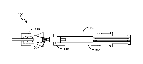
cable along conductors and strength members, perhaps causing damage as
described above.
BRIEF DESCRIPTION OF THE DRAWINGS
[0003] FIG. 1 depicts an example head assembly.
[0004] FIG. 2 depicts an example lower head attachment.
[0005] FIG. 3 depicts an example feed-through tube assembly.
[0006] FIG. 4 depicts an example of an upper head attachment.
[0007] FIG. 5A depicts an example upper compression seal assembly.
[0008] FIG. 5B depicts the example upper compression seal assembly in a pre-
assembled configuration.
[0009] FIG. 6 depicts an example gripper cone.
1
Date Recue/Date Received 2020-08-28
81791501
[0010] FIG. 7 depicts an example upper head attachment.
[0011] FIG. 8 depicts an example head assembly.
[0012] FIG. 9 depicts an exploded view of the head assembly of FIG. 8.
[0013] FIG. 10 depicts a pressure seal.
[0014] FIG. 11 depicts an example head assembly.
[0015] FIG. 12 depicts an exploded view of the head assembly of FIG. 11.
[0016] FIG. 13 depicts an example implementation utilizing a cable with a
sealing
termination during tractoring.
[0017] FIG. 14 depicts an example implementation utilizing a cable with a
sealing
termination.
[0018] FIG. 15 depicts an implementation for subsea intervention.
[0019] FIG. 16 depicts an example implementation utilizing a cable with a
sealing
termination.
DETAILED DESCRIPTION OF THE INVENTION
[0020] Certain examples are shown in the above-identified figures and
described in
detail below. In describing these examples, like or identical reference
numbers are
used to identify common or similar elements. The figures are not necessarily
to scale
and certain features and certain views of the figures may be shown exaggerated
in
scale or in schematic for clarity and/or conciseness.
[0020a] An aspect of the present disclosure relates to a head assembly for a
cable,
wherein the head assembly comprises: an upper head attachment; a lower head
attachment disposed within the upper head attachment, wherein a breakout
chamber
is located in the lower head attachment and filled with a fluid, and wherein a
rope
socket is located in the breakout chamber, wherein the breakout chamber is in
fluid
2
Date Recue/Date Received 2020-08-28
81791501
communication with a flow path, and wherein the flow path comprises a piston,
the
piston disposed in the lower head attachment; an upper compression seal
assembly;
and a gripper cone; wherein the fluid in the breakout chamber urges the piston
to an
expanded position away from the breakout chamber in response to an increase in
down hole pressure.
[0020b] An aspect of the present disclosure relates to a downhole system
comprising: a head assembly for a cable, wherein the head assembly comprises:
an
upper head attachment; a lower head attachment disposed within the upper head
attachment, wherein a breakout chamber is located in the lower head attachment
and
filled with a fluid, wherein the breakout chamber is in fluid communication
with a flow
path, and wherein the flow path comprises a piston, the piston disposed in the
lower
head attachment; an upper compression seal assembly; a gripper cone; and a
rope
socket located in the breakout chamber; a cable connected with the rope
socket; and
a downhole tool connected with the head assembly, wherein the cable is in
electrical
communication with the downhole tool; wherein the fluid in the breakout
chamber
urges the piston to an expanded position away from the breakout chamber in
response to an increase in downhole pressure.
[0020c] An aspect of the present disclosure relates to a method of connecting
a
cable with a tool, comprising: terminating the cable with a rope socket,
wherein the
rope socket is located in a lower head attachment that is connected and
disposed
within an upper head attachment; connecting at least a portion of the cable to
a
connecting wire of the tool in a breakout chamber formed in the lower head
attachment, wherein the rope socket is in the breakout chamber, and wherein
the
breakout chamber is in fluid communication with a flow path, and wherein the
flow
path comprises a piston, the piston disposed in the lower head attachment;
placing
the cable through a gripper cone, wherein the gripper cone is adjacent the
upper
head attachment; placing the cable through an upper compression seal assembly;
tightening the upper compression seal assembly to provide a pressure tight
seal
about the cable and tighten the gripper cone about the cable; and filing the
breakout
2a
Date Recue/Date Received 2020-08-28
81791501
chamber with a fluid, wherein the fluid urges the piston to an expanded
position away
from the breakout chamber in response to an increase in downhole pressure.
[0021] FIG. 1 depicts an example head assembly. The head assembly 100 includes
and upper head attachment 140. A lower head attachment 160 is located within
the
upper head attachment 140. A rope socket 130 is located in the lower head
attachment 130. A gripper cone is connected with the upper head attachment
140,
and a upper compression seal assembly 110 is connected with the gripper cone
120.
[0022] FIG. 2 depicts an example lower head attachment. FIG. 3 depicts an
example feed-through tube assembly. Referring to FIGS. 2 and 3, the lower head
attachment 160 has seals 240 located thereabout. The lower head
2b
Date Recue/Date Received 2020-08-28
CA 02907922 2015-09-23
WO 2014/179447
PCT/US2014/036139
attachment 140 also has feed-through tubes 230 located therein. The feed-
through tubes 230 can be operatively aligned with a breakout chamber 220. A
slot 210 for operatively receiving a retaining feature, such as a clip, is
formed
in the lower head attachment 160, and a rope socket is adjacent the slot 210.
[0023] FIG. 4 depicts an example of an upper head attachment. The upper
head attachment 140 is configured to receive at least a portion of the lower
head attachment. The upper head attachment can be threaded, fastened, or
otherwise connected with the lower head attachment.
[0024] FIG. 5A depicts an example upper compression seal assembly. FIG.
5B depicts the example upper compression seal assembly in a pre-assembled
configuration. The upper compression seal assembly 110 includes a first
member 510. The first member 510 can be connected with the upper head
attachment. The first member 510 can thread or otherwise be fastened to the
upper head attachment. The first member 510 can have an internal shape
configured to receive compression members 520. The second member 530
can also have an internal shape to receive the compression members 520.
[0025] The compression nut 540 can be connected with the first member 510.
The compression nut 540 can compress the compression members 520 as it
is tightened onto the first member 510.
[0026] FIG. 6 depicts an example gripper cone. The gripper cone 610 can
have a base and a tapered end 620. The tapered end 620 can have slit to
allow the gripper cone to close onto a cable as the gripper cone is tightened
into place. The gripper cone has small angled teeth to hold a cable in place.
[0027] FIG. 7 depicts an example upper head attachment. The upper head
attachment 140 can have an area 720 to attach with the gripper cone and
area 710 to attach with the upper compression seal assembly.
[0028] FIG. 8 depicts an example head assembly. FIG. 9 depicts an exploded
view of the head assembly of FIG. 8. Referring to FIGS. 8 and 9, the head
assembly 800 includes a fishing neck 810, an upper packoff bushing 840, a
compression tool 810, a lower packoff bushing 810, the rope socket 130, the
breakout chamber 220, a piston 820, and a fill port 830. The breakout
chamber 220 can be filled with filler material. The filler material can be
oil,
3
CA 02907922 2015-09-23
WO 2014/179447
PCT/US2014/036139
liquid, grease, or fluid. The filler material can be supplied to the breakout
chamber using the fill port 830.
[0029]The filler material may expand when in the presence of elevated
downhole temperatures. The resulting pressure of the expanding filler
material trapped inside the breakout chamber 220 may damage the
conductors and/or other components of a cable. The piston 820 can be used
to compensate for the expanding pressure.
[0030] For example, the cable may be terminated to the rope socket 130 and
wiring may be completed in the breakout chamber. The compression tool 820
located between upper and lower packoff bushings 840 and 810 at the uphole
end of the rope socket 130 may provide a high-pressure seal at the uphole
end of the breakout chamber 220. After the head assembly is assembled, the
breakout chamber 220 is filled with the filler material (e.g., oil, grease,
and/or
any other materials) via the fill port 830. The fill port may then be sealed
with
a plug and/or other means.
[0031]As the head assembly 800 is exposed to elevated downhole pressures,
the expanding filler material in the breakout chamber 220 may push, force,
and/or otherwise urge the piston 820 away from the breakout chamber 220.
Such movement of the piston 820 may thus relieve the pressure building
within the breakout chamber. As the temperature subsequently decreases,
the borehole pressure may similarly urge the piston back toward the breakout
chamber. The piston may, thus, also aid in preventing cross-contamination of
borehole fluids into the breakout chamber, which may otherwise damage the
conductors and/or other components therein. The lower head attachment
may also comprise stops operable to limit travel of the piston.
[0032] FIG. 10 depicts a pressure seal. The pressure seal 910 can be a one
way seal that allows flow in one way but prevents flow in a second direction.
The pressure seal 910 can be located in a housing 930. Seals in the housing
930 or around the seal 910 can prevent movement of the seal 910. The
housing 930 can have channels 940 in an uphole face.
[0033] FIG. 11 depicts an example head assembly. FIG. 12 depicts an
exploded view of the head assembly of FIG. 11. The head assembly includes
4
CA 02907922 2015-09-23
WO 2014/179447
PCT/US2014/036139
the fishing neck 810, the upper packoff bushing 840, the housing 930 with the
pressure seal 930, a lower packoff bushing 810, the rope socket 130, the
breakout chamber 220, a fill port 830, and the lower head attachment 160.
[0034]The channels in the housing 930 can provide a flow path for fluid
exiting the breakout chamber and the seal can allow fluid to flow out of the
breakout chamber. The seal can prevent other fluid from entering the
breakout chamber.
[0035] Referring now to FIG. 13, a cable having a sealing termination
according to one or more aspects of the present disclosure is indicated
generally at 1400. FIG. 13 depicts an example implementation utilizing a
cable with a sealing termination during tractoring, in which a tractor 1402 is
attached to the end of the cable 1400 when deployed in a wellbore or
borehole 1404, which may have one or more vertical, horizontal, deviated,
dog-legged, and/or multi-lateral wellbore sections.
[0036] Referring now to FIG. 14, a cable having a sealing termination
according to one or more aspects of the present disclosure is indicated
generally at 1500. Many offshore platforms utilize a means of supporting the
wellhead equipment 1502 when performing a wireline operation without the
use of the drilling derrick (not shown). A crane 1504 may be one manner of
doing this. A mast unit or other temporary derrick (not shown) may also or
alternatively be utilized. A standard wireline rig up offshore may utilize a
crane 1504 or mobile mast unit (not shown) to support both the upper sheave
wheel and the pressure equipment itself. A pack off assembly 1506 may
utilize an upper sheave 1508 mounted to the well head equipment 1510 itself
at the top of the lubricator 1512.
[0037] Referring now to FIG. 15, a cable having a sealing termination
according to one or more aspects of the present disclosure is indicated
generally at 1700. FIG. 19 depicts an implementation for subsea intervention.
A lubricator system may be lowered onto the subsea well head 1702, using
grease injection into flow tubes to establish a dynamic pressure seal
(stuffing
box 1710), with the cable returning through open water back to surface on the
intervention vessel (not shown) or the rig/platform 1704. For shallow water
CA 02907922 2015-09-23
WO 2014/179447
PCT/US2014/036139
applications, the grease injection system, including the grease tank, can be
installed on the vessel or rig/platform 1704, and pressurized grease can be
conveyed to the grease head at the seabed 1706 through a control umbilical
(not shown) or through a dedicated hose (not shown). For well intervention
operations with a subsea lubricator in deep water, the injection system 1708
may be placed subsea.
[0038]Referring now to FIG. 16, a cable having a sealing termination
according to one or more aspects of the present disclosure is indicated
generally at 1800. The cable 1800 may be utilized in combination with a
spoolable compliant guide system 1802. A pack-off type dynamic seal may
be retrievable through the compliant guide 1802.
[0039] Other implementations within the scope of the present disclosure may
logging with a cable having a sealed termination as described above while a
fluid is injected in the well.
6