Note: Descriptions are shown in the official language in which they were submitted.
286634-3
1
A CONDUCTOR FOR ELECTRICAL EQUIPMENT
TECHNICAL FIELD AND PRIOR ART
The present invention relates to a conductor for
electrical equipment, and in particular to a movable contact
for a disconnector in air-insulated installations for
transmitting and distributing high voltage electricity.
More generally, the invention also relates to a
switch for air-insulated installations for transmitting and
distributing high voltage electricity.
The main intended field of application is high
voltage, but the invention is equally applicable to a medium
or low voltage conductor.
The invention relates more particularly to
reducing the weight of such a conductor.
A high voltage electricity substation comprises
in particular a set of circuit breakers and disconnectors.
In a substation, a disconnector performs a safety
function: it is opened after the circuit breaker has opened
in order to make any intervention on the substation safe.
In known manner, a disconnector comprises a
stationary contact and a contact that is movable in pivoting
about an axis, which movable contact is usually referred to
as a "blade".
When the disconnector is closed, the movable
contact and the stationary contact are in mechanical and
electrical contact with each other.
The movable contact is in a substantially
horizontal position when the disconnector is closed and in a
Date Recue/Date Received 2021-03-29
CA 02908076 2015-09-25
, S 53919 PM-G
2
substantially vertical position when the disconnector is
open.
The stationary contact is made up of a set of
interconnected parts within which the movable contact is
received when it is moved.
Such a disconnector gives satisfaction in terms
of operating safety, and the effectiveness with which it
conducts current.
In International patent application WO
2010/106126, the applicant has proposed such a high voltage
disconnector that is also of simplified design.
The need to withstand high levels of mechanical
stress when the movable contact needs to be operated together
with extra weight due to ice requires equipment that operates
when iced to be reinforced compared with the specifications
for equipment that is to operate without ice. In other words,
for utilization under winter conditions where ice might form,
it is necessary to over-dimension the mechanical parts that
are used for actuating the movable contact. However that
greatly increases the cost price of the equipment.
Furthermore, the need to comply with high levels
of thermal stress requires the designers of a disconnector
two over-dimension the movable contact relative to its
specifications in terms of conducting current.
More exactly, the designers need to increase the
right section of the movable contact. In so doing, the right
section of said contact is increased so its electrical
resistance is decreased, thereby preventing the contact from
heating.
However, increasing the right section of the
movable contact (the blade) leads to an increase in its
weight.
, CA 02908076 2015-09-25
. S 53919 PM-G
3
A disconnector must also be capable of
withstanding a high level of seismic activity. Unfortunately,
the heavier the parts that are used to make it, the poorer
the ability of a disconnector to withstand seismic activity.
In summary, the following constraints need to be
confronted:
= in normal operation, any temperature rise to
which a high voltage (HV) disconnector is subjected must be
limited to a threshold;
. a disconnector must also be capable of
operating when subjected to a certain level of stress due to
the weight of ice, which weight can be considerable; and
= a disconnector must also withstand certain
seismic constraints, and they too can be considerable.
It has been found that the weight of the
blade, i.e. of the movable contact of the disconnector, in
particular when it is weighed down by ice, is a factor that
is harmful, leading to the disconnector breaking when it
needs to operate under a weight of ice and when it is
subjected to earthquakes (with or without ice) and it is in
the open position.
There is therefore the problem of reducing the
weight of the conductor as much as possible, while also
dissipating any ice that might be deposited thereon.
There is also the problem of reducing the weight
of the blade of a high voltage disconnector as much as
possible, without thereby causing it to overheat during
operation of the disconnector.
An object of the invention is thus to propose
electrical equipment, more particularly a disconnector of the
type described above, that makes use of parts that are
lighter in weight, in particular a movable contact that is
CA 02908076 2015-09-25
S 53919 PM-G
4
lighter than the movable contacts of electrical equipment in
the prior art.
Such equipment should preferably accommodate high
levels of thermal stress and should be capable of operating,
when iced, using mechanical parts that are smaller, and
therefore less expensive, while nevertheless providing
operation that is satisfactory under icing conditions in
winter.
SUMMARY OF THE INVENTION
To do this, the invention provides a conductor
for electrical equipment comprising at least one section
member of electrically conductive material that is elongate
along a longitudinal axis (Y), the conductor having an
outside surface in which at least a portion forms
corrugations in a plane perpendicular to the longitudinal
axis, which corrugations also extend on said outside surface
along a direction that is parallel to the longitudinal axis
(Y).
The invention also provides a conductor for
electrical equipment, the conductor comprising at least one
section member of electrically conductive material that is
elongate along a longitudinal axis (Y), the conductor having
an outside surface in which at least a portion forms fluting
or grooves that extend in a direction parallel to the
longitudinal axis.
The corrugations or fluting or grooves lengthen
the perimeter of the outside surface and increase the surface
area for dissipating heat energy from the section member to
the ambient air or to any ice (and/or snow) that has become
deposited thereon.
CA 02908076 2015-09-25
S 53919 PM-G
They serve to cause current to flow in non-
uniform manner, creating localized heating on the outside
surface, which heating is compensated by convection of the
ambient air.
5 It should be recalled that the phenomenon of
natural convection consists in heat being transferred from a
solid body (here: the conductor) and the freely-moving
surrounding air.
The transmission of heat to the surrounding air,
due to the Joule effect that results from current flowing in
the conductor, has the effect of causing the density of the
air to vary. Air is thus caused to flow because of buoyancy
thrust. It is therefore this thrust force due to varying air
density that is at the origin of the natural convection,
which is also said to be "free" convection, that takes place
around the conductor.
With such a conductor, disengagement of ice
involves several physical phenomena.
Firstly, thermal conduction between the conductor
and the ice (and/or the snow) causes a portion of it to melt,
which portion therefore runs off as water.
In addition, the portion of the ice (or of the
snow) that is directly in contact with the conductor, and
that is transformed into water, itself acts as a lubricant,
thereby facilitating mechanical disengagement of the ice
(and/or of the snow) that remains when the body that retains
it begins to move.
Water evaporation tends rather to cool the blade
using the above-mentioned lubricating water. This water has
remained on the body of the conductor and it evaporates
because of heat exchange. Coupled with the phenomenon of air
convection, the water vapor serves to remove even more heat
,
CA 02908076 2015-09-25
, S 53919 PM-G
6
energy than can be removed by the convection phenomenon
alone.
The undulations or the fluting or the grooves
form a surface that can become clogged by ice (and/or snow).
This leads to that surface becoming heated because natural
convection is prevented, while improving the conduction of
heat energy to the ice. In other words, ice (and/or snow) on
the conductor prevents air convection. However, by becoming
deposited directly on the portion of the conductor where it
is locally heated, it absorbs the heat that would otherwise
be dissipated into the air.
Compared with the prior art, the effects of
disengaging any ice (or snow) enable the weight of the
conductor to be reduced, for given ice (and/or snow)
conditions.
The invention thus enables the weight of the
blade of a conductor to be reduced, and in particular the
weight of a high voltage disconnector blade. Consequently, it
serves to reduce the stresses to which the mechanical parts
actuating the conductor are subjected under ice (and/or snow)
conditions. The invention is thus adapted to systems that
perform de-icing by injecting high currents.
For given conductor diameter, the corrugations or
the fluting or the grooves enable the heat transfer surface
area involved in convection and/or radiation to be increased;
under such circumstances, the section member may be anodized.
Furthermore, a rounded shape for the corrugations
or the fluting or the grooves makes the conductor more
aerodynamic by contributing to better airflow.
It is preferable for the corrugations or the
fluting or the grooves to be of rounded shape so as to avoid
the point effects that are inherent to fins of triangular
CA 02908076 2015-09-25
S 53919 PM-G
7
and/or rectangular shape of the kind usually used in the
industry, thereby reducing dielectric stresses at high
voltage.
The outside surface of the conductor may be
provided with corrugations that are simple and/or complex. As
an example of complex corrugations, mention may be made of
corrugations having fractal geometry, comprising main
corrugations, each of which is provided with secondary
corrugations.
The conductor is hollow inside, the hollow being
of cylindrical shape over all or part or, or most of the
length of the conductor.
The cylinder may have an inside diameter lying in
the range 2.5 centimeters (cm) to 7.5 cm, or even 10 cm.
The thickness of the ring may lie in the range
5 millimeters (mm) to 2.5 cm.
The conductor of the invention is particularly
adapted to making a movable contact for a disconnector.
Preferably, the conductor has two support
elements that are spaced apart from each other along a
longitudinal axis.
More preferably, each of the support elements is
arranged at one of the longitudinal ends of the conductor.
According to an advantageous characteristic, a
conductor of the invention includes at least one electrical
contact element for coming into contact with a distinct
electrical contact in order to provide an electrical
connection. Each contact element can then be fastened to the
corrugated section member of the conductor. When there are
two electrical contact elements, the corrugations are shared
between the contact elements.
CA 02908076 2015-09-25
S 53919 PM-G
8
A conductor as described above may further
include at least one lateral projection extending beyond the
outside surface of the conductor in said plane perpendicular
to the longitudinal axis.
Each lateral projection may have an outside
surface with a portion provided with corrugations in a plane
perpendicular to said longitudinal axis.
Each lateral projection may have an outside
surface with a portion that is plane.
Each lateral projection may provide electrical
contact or may be provided with a part for providing
electrical contact.
Two lateral projections may be provided that are
arranged symmetrically on either side of a plane of symmetry
of the conductor.
For simplicity of fabrication, the section member
is preferably made by extrusion.
It is preferably made of aluminum or of copper or
of aluminum or copper alloy.
A conductor of the invention may be provided with
pivot hinge means at one of its ends.
A conductor of the invention may include at least
one lateral reinforcement means. Said means may be provided
with a hollow or a recess that is open towards the hollow, or
towards the hollow portion, of the conductor.
The invention also provides high voltage
electrical equipment including at least one conductor of the
invention and at least one electrical contact with which said
conductor is suitable for coming into contact.
In such electrical equipment, at least one of the
electrical contacts may have a plurality of separate contacts
CA 02908076 2015-09-25
S 53919 PM-G
9
with which a common lateral portion of said conductor can
come into contact.
The conductor of the invention may be stationary,
said electrical contact being a movable contact.
In a variant, the conductor of the invention is
movable, said electrical contact being a stationary contact.
The invention also provides such electrical
equipment in which said electrical contact is U-shaped.
Each branch of the U-shape may include at least
one stationary contact extended by a tab folded inwards so as
to be substantially parallel to the branch of the U-shape
that it extends, said tab being designed to come into
mechanical contact with at least one contact element of the
movable contact.
Return means may be interposed between the tab
and the branch of the U-shape it extends, in order to urge
the tab inwards towards the movable contact when it is in
contact with the stationary contact.
The invention also provides a high voltage
disconnector including electrical equipment as described
above.
The invention also provides a high voltage
disconnector including an electrical conductor as described
above that is mounted by pivotal hinging on an insulating
support, and at least one electrical contact with which said
conductor is suitable for coming into contact by a pivoting
movement e.g. on an insulating support.
The invention also provides an operating method
for operating a conductor or electrical equipment or a
disconnector of the invention, wherein current flows from one
end of the conductor to the other, giving off heat by the
Joule effect in its wall. Ice and/or snow that has
CA 02908076 2015-09-25
S 53919 2M-G
accumulated in the corrugations or fluting or grooves can
then melt effectively.
BRIEF DESCRIPTION OF THE DRAWINGS
The invention can be better understood with the
5 help of the following description and of the accompanying
drawings, in which:
= Figure 1A is a side view of an embodiment of a
disconnector of the present invention in the closed position;
= Figure 1B is a side view of the Figure 1A
10 disconnector, but in the open position;
= Figures 2A, 2B, and 2C are enlarged views
respectively from the side, from above, and end-on from the
right-hand side showing the stationary contact of the high
voltage disconnector S of Figures lA and 1B;
= Figure 3A is a cross-section view of a
conductor in an embodiment of the invention and without a
contact element;
= Figure 3B is a cross-section view of a
conductor in a variant embodiment of the invention and
without a contact element;
= Figure 4A shows a detail of the cross-section
view of a conductor in an embodiment of the invention;
- Figure 4B is a profile view of a conductor in
an embodiment of the invention; and
= Figure 5 is a side view of a lateral contact
element for a conductor of the invention.
DETAILED DESCRIPTION OF PARTICULAR EMBODIMENTS
The description below relates to a conductor of
the invention.
,
CA 02908076 2015-09-25
S 53919 PM-G
11
A particular application relates to it being used
in a high voltage disconnector. However the conductor of the
invention may be used in any type of electrical equipment in
which a conductor is required. In addition, the conductor is
described as being movable; however a conductor that is
stationary does not lie outside the ambit of the present
invention.
In Figures lA and 1B, there can be seen an
example of a high voltage disconnector S. e.g. for a voltage
of about 245 kilovolts (kV), to which the conductor of the
invention may be applied.
This disconnector S comprises a movable contact 2
formed by a conductor of the present invention that is
elongate along a longitudinal axis. Two stationary contacts 4
and 4' are arranged on insulating supports 8 and 10 that
enable them to be held at a distance from the ground or from
a support 7. Each of the stationary contacts is designed to
be in mechanical contact with a respective one of the ends of
the movable contact.
One of the stationary contacts 4 is mounted on
the insulating support 8, while the other stationary contacts
4 is mounted on the insulating support 10.
In the example shown, the insulating support 8 of
the movable contact 2 is made up of two columns 8.1 and 8.2.
The insulating support 10 is made up of a single column. Each
column is arranged perpendicularly to the ground or to the
surface of the support 7.
In a high voltage disconnector S, the movable
contact 2 is commonly called a "blade". In this example it is
mounted to pivot about an axis that is substantially
orthogonal to the plane of the figure, in order to cause the
disconnector to pass from a closed position (conductor in a
CA 02908076 2015-09-25
S 53919 PM-G
12
substantially horizontal position, Figure 1A) to an open
position (conductor in a substantially vertical position,
Figure 1B).
More exactly, it is hinge-mounted on the
insulating support 8. It is this support that supports the
hinge mechanism of the movable contact 2.
In the description below, and by convention, a
reference frame is defined having three mutually orthogonal
axes X, Y, and Z, with the axis Y being the longitudinal axis
of the conductor 2 when the conductor is in the closed
position.
The stationary axis Z is in alignment with the
direction of the insulating support 10, and it is
perpendicular to the ground or to the horizontal surface of
the support 7. It is in alignment with the vertical direction
at the location where the device is installed.
The axis X is perpendicular to the axes Y and Z.
In Figure 2C, the axis X is the axis that is
directed horizontally and the axis Z is the axis that is
directed vertically.
In other words, in the closed position
(Figure 1A), the conductor 2 co-operates with the stationary
axes X and z to define an orthogonal system of axes x, Y, and
Z.
In the disconnector S that is shown, the movable
contact 2 of the invention is electrically connected to a
high voltage electricity network via a distinct electrical
contact and a connection 12 that extends substantially
horizontally.
The stationary contacts 4 are connected to the
network via a connection 13 of structure similar to that of
the connection 12.
CA 02908076 2015-09-25
S 53919 PM-G
13
Thus, when the disconnector S is in the closed
position (Figure 1A), current coming from the high voltage
distribution network can pass from one of the connections,
e.g. the connection 12, to the other connection, e.g. the
connection 13.
The invention also applies to a disconnector
having only one stationary contact 4.
The mechanism for actuating the disconnector is
of conventional type and is not described in detail. In an
example, it includes a spiral tape spring for balancing the
blade 2 of the disconnector. The insulating column 8.1 also
forms a control rod for controlling the movement of the
moving contact or blade 2.
In the example shown, the two stationary contacts
4 and 4' are similar in structure: as a result only one of
them is described in detail below.
Such a stationary contact 4 is of substantially
U-shaped section forming a jaw, with its two branches being
substantially parallel and electrically conductive. These two
branches define a gap in which the movable contact 2 is
positioned when the disconnector is in the closed position,
electrical conduction taking place between the movable
contact and the parallel branches.
More exactly, and as can be seen in Figures 2A
and 20, the stationary contact 4 comprises a U-shaped part
30, this part being fastened to the insulating support 10 via
its bottom 30.1. It has two branches 30.2 and 30.3 that are
substantially parallel to each other, with the movable
contact 2 in the closed position being positioned between
them.
Each branch 30.2 and 30.3 is extended by a
respective inwardly-folded tab 32.2 or 32.3 that is to come
CA 02908076 2015-09-25
S 53919 PM-G
14
:ftg
into contact with a contact element 16.2 or 16.1 of the
movable contact 2, as described below.
The branches 30.2 and 30.3 of the U-shape are
made out of aluminum or of aluminum alloy, for example. The
tabs 32.2 and 32.3 may be made of silver-plated copper.
Resilient means 34, e.g. respective coil springs
34.2, 34.3, are advantageously provided between each tab
32.2, 32.3 and the corresponding branch 30.2, 30.3, thereby
urging the tab 32.2, 32.3 towards the inside of the
stationary contact.
This improves electrical contact between the tab
and the corresponding contact element of the movable contact.
In the example shown, the tabs 32.2, 32.3 are
fitted to the respective branches 30.2, 30.3 by screw
fastening.
The movable contact 2 of the present invention is
described below in greater detail with reference more
particularly to Figures 3 and 4A, 4B.
The movable contact 2 of the invention is much
lighter in weight than the contacts that have been used in
the past in high voltage disconnectors used when ice-free and
when iced, while nevertheless allowing electric current to
pass between the connections 12 and 13.
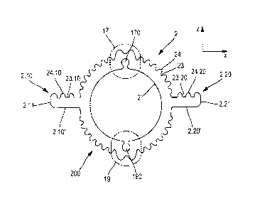
Figures 3A and 3B are both cross-section views
(on the X,Z plane) of a conductor 2 of the invention, mounted
as the movable contact of the high voltage disconnector in
the example of above-described Figures lA and 1B.
By way of example, each cross-section is taken on
the side of the end 2.2 of the conductor 2 in a zone outside
the zone including the contact branches of the stationary
contact 4. The conductor is hollow, having an inside surface
2'.
CA 02908076 2015-09-25
' S 53919 PM-G
The device shown in cross-section in Figure 3A,
including zones reinforced by lateral reinforcement means 17,
19, is adapted to operate with a relatively high current,
e.g. about 3000 amps (A). Preferably, it is used for voltages
5 below 115 kilovolts (kV) or 150 kV or 200 kV, because it is
more sensitive to radio interference than the device shown in
Figure 33.
Each of the lateral reinforcement means 17, 19
may be made along the length of the conductor.
10 It contributes to passing the flow of current,
and also to cooling.
The device shown in cross-section in Figure 3A,
without a reinforced zone 17, 19, is adapted to operate with
a lower current, e.g. about 2500 A, but may be used at a
15 higher voltage, greater than 115 kV or 150 kV or 200 kV.
In each cross-section, the movable conductor (or
blade) 2 includes corrugations 23, 24 over at least a
fraction of its outside periphery, or indeed over nearly all
of its outside periphery. The bottom zone 200 is preferably
also provided with corrugations; this then can become clogged
with ice when the equipment is in the open position. On being
closed, heating will then give rise to the same effects as
those described above.
In the structure of Figure 3A, saw cuts or
"kerfs" may be provided in the zones 17 and 19 in order to
create a chimney effect; they serve to improve cooling. These
kerfs may be placed along a vertical axis, passing through
the zones 17 and 19, and for example joining both hollows or
recesses 170, 190.
In this same structure, the reinforced zone(s)
17, 19 having outermost portions that project beyond the
CA 02908076 2015-09-25
S 53919 PM-0
16
outside diameter defined by the tops of the corrugations 24,
serve to protect these kerfs dielectrically.
The notches 170, 190, which are open towards the
inside of the conductor, make it possible to fasten a plate
to the end of the blade, said plate being perpendicular to
the axis of the hollow conductor, and also to fasten the
blade to the contact 4' at the end 2.1 (e.g. likewise using
two screws). A plate perpendicular to the axis of the hollow
conductor may for example have two holes in alignment with
the inside recesses 170, 190 of the extrusion, making it
possible to block the hollow of the conductor using two
screws, e.g. self-tapping screws, that enable said plate to
be fastened to the end of the hollow tube.
As can be seen in greater detail in Figure 4A,
the corrugated outside surface of the conductor has
alternating portions 23 and 24 that are low and high relative
to the inside surface 2'. The high portion 24 preferably
presents a profile that is rounded, close to a portion of a
circle of radius r. By way of example, r is less than or
equal to 3 mm, still by way of example: r = 1 mm or
r = 1.5 mm. The low portions do not need to have this rounded
shape.
In other words, the outside surface of the
conductor presents an altitude h relative to the inside
surface 2' that varies between a minimum value hmin that
corresponds to the lowest zones 23, and a maximum value hrmax
that corresponds to the highest zones 24. The difference
hmd, - h.,õ, between these two values preferably lies in the
range 6.5 mm to 9.5 mm, and more generally between 5 mm and
2.5 cm. The diameter of the cylinder defined by the inside
surface 2' may for example lie in the range 2.5 cm and
7.5 cm.
CA 02908076 2015-09-25
S 53919 PM-G
17
In other words, and as can also be seen in
Figure 4B, which shows a portion of the outside surface of
the conductor in side view, this outside surface presents
corrugations or fluting or grooves 230 that extend
longitudinally, parallel to the axis Y, over a fraction of
the length (along Y) of the conductor, or even over its
entire length.
As can be understood from Figure 4A, the
corrugations create a perimeter that is longer than the
perimeter that would result from a smooth outer profile 210
(drawn in interrupted lines in Figure 4A). The outside
surface area of the conductor is thus likewise greater than
the surface area that would result from a smooth surface of
the kind marked in this figure by the trace 210.
Such a topology creates a "radiator" effect and
encourages heat exchange with ambient air. This increases the
effectiveness of the conductor by several tens of percent,
e.g. by at least 50%, in particular when the blade is exposed
to wind or rain.
In addition, if a rounded shape is selected from
the corrugations (as shown in Figure 4A), high voltage
dielectric stresses are reduced, in contrast to other shapes
such as triangular or rectangular shapes of the kind usually
to be found in conventional radiators.
In the event of ice and/or snow accumulating, the
corrugations that are responsible for the dissipation
effectiveness of the conductor find themselves clogged by
that ice and/or snow. More precisely, the ice and/or the snow
accumulates in the low portions 23 of the corrugations
(Figure 4A). Consequently, the high percentage of heat
dissipation that would normally take place in air, now takes
place in the ice and/or the snow, thereby encouraging it to
= CA 02908076 2015-09-25
' S 53919 PM-G
18
dissipate, where the presence of such ice and/or snow is
harmful to and mechanically stresses the operation of the
disconnector.
In conventional blades, reliance tends to be made
on having a conductor of large section in order to reduce its
electrical resistance and thus avoid any electrical heating,
instead of relying on a larger convective and/or radiative
surface area for heat exchange with ambient air in order to
dissipate the heat; any ice and/or snow that is deposited
then receives very little heat energy and therefore does not
melt. By way of example, a conductor of the invention has an
outside diameter of 101.6 mm and an inside diameter of
85.4 mm.
The corrugations may be simple, as shown in
Figure 3A or 3B; in a variant, it is also possible for them
to be complex, for example they could present fractal
geometry; each individual corrugation is then provided with
secondary corrugations at its periphery.
The conductor described herein is thus easy to
incorporate in systems for de-icing electricity networks.
By way of example, the section member 2 is made
of aluminum or of copper or of an aluminum or copper alloy.
It may be obtained by an extrusion technique.
The conductor 2 is of generally elongate shape,
being hinged at one of its longitudinal ends 2.1 on the first
insulating support 8.
Its other longitudinal end 2.2, remote from its
end 2.1, may be provided with one or two (or more than 2)
lateral projections 2.10, 2.20 that extend(s) beyond the
outer periphery of the conductor, and that serve(s) to
provide electrical contact, e.g. by coming directly into
contact with a stationary contact 4 arranged on the
1 CA 02908076 2015-09-25
S 53919 PM-G
19
insulating support 10. These lateral projections 2.10, 2.20
may be made using the body of the conductor.
The corrugations 23, 24 are distributed over the
outside surface of the conductor, between these lateral
projections.
As can be seen in Figures 2C and 3A, a portion of
the outside surfaces of these lateral projections, preferably
in their top surfaces (that face upwards when the contact is
in the closed position, as shown in Figure lA and 2C) may in
itself also be provided with corrugations in cross-section,
having alternating portions 23.10, 24.10 and 23.20, 24.20
that are high and low relative to a plane surface. The high
portions are preferably of rounded profile, close to a
portion of a circle of radius r, which may be comparable to
that described above for the corrugations 24, e.g.
r = 1.5 mm.
These corrugations are preferably distributed
over a portion that is not intended to provide directly the
electrical contact itself.
They have the same effect as that described above
for the corrugations on the body of the conductor.
As in Figure 4B, these corrugations define
corrugations or fluting or grooves extending parallel to the
axis Y.
Contact elements 16.1, 16.2 may be provided for
pressing against these lateral projections. By way of example
these may be extrusions. As shown in Figure 5, they are of
elongate shape, having a top surface 16.20 and a bottom
surface 16.20', with a plane or rounded lateral end 16.21 for
providing the electrical contact itself with the
corresponding portions of the contact 4. They come into
contact against the projections 2.20, 2.10, e.g. by pressing
CA 02908076 2015-09-25
S 53919 PM-G
the top surface 16.20 against the bottom surface 2.20' of the
lateral projection. Figure 5 shows the contact element 16.2,
and a similar description is applicable for the contact
element 16.1 and the corresponding lateral projection.
5 These contact elements 16.1, 16.2 may be
assembled onto each of the portions 2.10, 2.20, e.g. by
bolts.
The arrangement of these contact elements 16.1,
16.2 on the section member 2 is shown in Figures 2B and 2C,
10 which show the physical contact between the stationary
contact elements and the contact elements 16.1, 16.2 of the
movable conductor 2 of the invention, when a disconnector is
in the closed position: each of the contact elements 16.1,
16.2 is pressed against one of the tabs 32.2, 32.3 of the
15 stationary contact 4.
In Figure 2C, there can be seen only two contact
elements 16.1, 16.2 and two branches 30.2, 30.3 of the
stationary contact 4. The movable contact 2 of the invention
may include two contact elements 16.1 and 16.2 at each of its
20 ends. Each of these contacts 16.1, 16.2 may be associated
with one to five contacts such as the contacts 32
(Figure 2A), with which the contact 16.1 16.2 comes into
electrical contact.
Each of the two contact elements 16.1, 16.2 of
the movable conductor 2 may be provided with a length (along
the axis Y) that is sufficient to extend over the length of a
plurality of stationary contacts 32, e.g. about five such
stationary contacts. This ensures permanent contact between
the stationary contact 4 and the movable conductor 2, even in
the event of movement by short circuit along the axis Y.
CA 02908076 2015-09-25
S 53919 PM-G
21
Stationary contacts having some other number of
contact branches would not go beyond the ambit of the present
invention.
The contact elements 16.1, 16.2 are preferably
made of silver-plated copper.
The first longitudinal end 2.1 of the section 2
may also include contact elements for co-operating with the
other stationary contact 4' that is arranged on the other
insulating support 8.
The general operation of the disconnector of the
present invention is similar to that of a disconnector of
conventional type, and it is not described herein in detail.
Reference may advantageously be made to the patent
application WO 2010/106126 mentioned in the introduction, in
particular for an explanation about how short circuit current
flows from the movable contact towards the stationary contact
by passing via the two contact elements 16.1, 16.2 when the
disconnector is closed.
In the example shown in Figures 3A, 3B, the
movable contact 2 of the invention is rigid as a result of
its tubular shape. Thus, it does not deform under the effect
of stresses when the disconnector is in operation; the
stationary contact 4 is suitable for deforming in order to
adapt itself to the size of the movable contact 2 in
operation. Deformation of the stationary contact 4 may be
obtained by virtue of means having elastic properties, for
example in this embodiment the flexible tabs 32.2, 32.3 and
the coil return springs 34.2, 34.3. Thus, the size of the gap
increases when the movable contact 2 penetrates into the
stationary contact 4, and it adapts itself to the transverse
dimension of the movable contact 2, with this dimension being
defined by the distance between the ends of the contact
CA 02908076 2015-09-25
S 53919 PM-G
22
elements 16.1, 16.2 that point radially outwards and that are
themselves fastened to the section member 2.
The electrical contact as obtained in this way
between the movable conductor 2 of the invention and a
stationary contact 4 is of very good quality, even at very
high voltages.
Finally, as shown In Figures 2A - 20, abutment
means along the axis Y may be provided, in order to limit the
recoil movement of the section member 2 during an electrical
short circuit. These means are formed by the curved end of
the arcing horn 36 of the movable contact 2, which is
suitable for coming into abutment against one or more spark
arresters 31 that are fastened to the part 30 and that extend
on either side of the axis Y. This arrangement is shown in
Figure 2B, as seen from above the structure of Figure 2A.
By means of the arrangement of corrugations or
grooves or fluting all around the blade, which corrugations
(or grooves, or fluting) become filled with ice and/or snow,
the invention makes it possible to heat the ice and/or snow
and consequently facilitates the release of such ice (or
snow) when operating the disconnector.
Consequently, other things remaining equal,
because the ice and/or snow is easily removed, it is possible
to avoid over-dimensioning the mechanical parts that are used
for actuating the blade. The corrugations (or grooves or
fluting) also serve to lighten the conductor as a result of
the convection phenomenon that is used to better advantage
with this radiator shape.
The invention makes it possible to reduce the
weight of the de-iced conductor compared with a conventional
conductor by up to 30% for a high voltage disconnector blade
made of aluminum.
CA 02908076 2015-09-25
A S 53919 PM-G
23
The radiator shape of the blade also makes it
possible in ice-free (or snow-free) conditions to reduce the
weight of the blade by about 30% compared with a prior art
blade.
Other improvements or variants may be envisaged
without thereby going beyond the ambit of the invention.
As mentioned above, the conductor of the
invention is suitable for any type of electrical apparatus
for providing intermittent or continuous electrical contact.
In particular, the conductor of the invention may
be a stationary contact that is installed once and for ever.
In a stationary configuration, when installed in permanent
manner, the conductor is suitable for being shaped as a
result of its intrinsic flexibility and because of the
resilient means for urging apart the contact elements. Its
shape can thus adapt as necessary to match other components
with which it is electrically connected.
In the event of the conductor serving to connect
together electrically two portions of electrical equipment,
it may have contact elements at both of its longitudinal
ends: the contact elements at one end come into contact with
one portion of the electrical equipment, and the contact
elements at the other longitudinal end come into contact with
the other portion of the electrical equipment. Under such
circumstances, current flows in the longitudinal direction
and between one longitudinal end and the other.
When the conductor is a movable conductor, the
present invention is not limited to a contact that moves in
pivoting, but also applies to a contact that is movable in
translation and to a contact that is movable in translation
and/or in pivoting.
CA 02908076 2015-09-25
= S 53919 PM-G
24
Furthermore, the conductor of the present
invention may have more than two contact elements.
The electrical equipment of the present invention
is lighter in weight than equipment of the prior art, in
particular disconnectors. Because of this reduced weight, the
ability of a disconnector of the invention to withstand high
levels of seismic stress and to withstand being operated when
iced, is increased.
Although described with reference to a section
member having 38 corrugations that are exposed to ice and/or
snow, a conductor of the invention may be divided with a
larger number (or smaller number) of corrugations.
Finally, although all of the corrugations in the
example described have the same simple rounded shape, it is
possible in the ambit of the invention to provide shapes that
are more complex (main corrugations provided with secondary
corrugations of the kind to be found in fractal geometries)
and of greater length, while also maintaining their ability
to be clogged with ice and/or snow in order to encourage
heating of the conductor. Furthermore, reducing the weight of
the conductor by reducing its right section contributes to
increasing its electrical resistance and thus to increasing
heating.
It is possible to achieve a reduction in weight
of about 30% compared with the members of circular section
that are usually used for electrical equipment and for a
given current being conveyed by said equipment. As explained
above, this reduction in weight of about 30% is naturally
advantageous when the electrical equipment is subjected to
seismic stresses.
The invention also presents advantages for
applications where it is desired to save weight and/or
CA 02908076 2015.5
. S 53919 PM-G
material for a conductor. For example, it may be advantageous
to have such a reduction in busbars, i.e. current-conducting
bars that connect together various pieces of electrical
equipment.
5 Thus, for copper-based conductors that are
normally used, it is possible to make them in accordance with
the invention from copper extruded profile, thereby achieving
substantial savings in fabrication costs, given the
constantly increasing price of copper.
10 Although the invention is described above with
reference to a high voltage electrical equipment, and more
specifically for a high voltage disconnector blade, the
invention is equally applicable to low voltage or medium
voltage equipment, e.g. to busbars.
15 During operation of a conductor or of electrical
equipment or of a disconnector of the invention, current
flows from one end to the other of the conductor, thereby
generating a Joule effect in its wall. Any ice and/or snow
that has accumulated in the corrugations or fluting or
20 grooves will be able to melt effectively, with the help of
the effects that are described above.
The invention proposes a conductor of smaller
weight in comparison with a conventional conductor for given
current and heating threshold, by means of a reduction in the
25 right section of the conductor.
In a conductor of the invention, heating for a
given current is less than that in a conventional conductor,
even though its electrical resistance is higher because of
the reduction in its cross section, with this being the
result of its larger convective and/or radiative surface
area.
CA 02908076 2015-09-25
S 53919 PM-G
26
A conductor of the invention presents an
acceptable current that is higher than that of a conventional
conductor of larger cross section, as a result of its larger
convective and/or radiative outer surface area. The conductor
is thus well adapted to applications for de-icing by
injecting high currents.
The electrical resistance of such a conductor is
greater than that of a conventional conductor because of the
reduction in its cross section. Thus, the Joule losses that
are generated therein when passing a given current are
greater, and they therefore enable de-icing to take place
more quickly than with a traditional conductor.