Note: Descriptions are shown in the official language in which they were submitted.
CA 02908324 2015-09-29
1
PCT/EP2014/056619 (WO 2014/161899) ¨ English translation
Suspension System for an Inner Container Mounted for Thermal Insulation in an
Outer
Container and Container Arrangement
The invention relates to a suspension system for an inner container mounted
for thermal
insulation in an outer container.
Furthermore, the invention relates to an arrangement of an outer container and
of an inner
container mounted for thermal insulation in the outer container.
From Document EP 0 014 250 Al, a suspension system for a cryogenic tank is
known, by
means of which the cryogenic tank is suspended in an outer container in a
thermally
insulated manner. The suspension system comprises several securing straps,
each composed
of several series-connected single elements of different fibre materials,
wherein the single
element of each securing strap which is closest to the tank is made up of the
fibre material
having the comparatively lowest thermal expansion coefficient. The securing
straps are able
to absorb only tensile forces, but no compression forces. Therefore, it is
necessary to group
the securing straps to two fixed bearings engaging opposite end regions of the
cryogenic
tank, with the tensile forces of the two fixed bearings acting in opposite
directions. A fixed
bearing results only from the sum of all securing elements. A prerequisite for
this is a
geometric arrangement of the securing elements which compensates for the
thermal length
changes of the respective containers and of the securing straps themselves as
far as possible,
since, otherwise, the thermal tensions would burden the device up to the
admissible load
limit.
From DE 196 25 492 Cl, a toroidal cryotank filled with liquid helium is known,
which, via a
suspension system, is suspended coaxially in a cylindrical outer container
aboard a research
satellite. The suspension system consists of an upper and a lower rectangular
frame, each
composed of tension and pressure bars in the manner of a framework, and tie
rods running
under prestress obliquely between the respective corner points of the
rectanguar frames and
the outer container. Thus, the cryotank is connected to the outer container
only via the tie
rods. The tie rods are able to absorb only tensile forces, but no compression
forces.
From Document US 3,115,983, a suspension system for a multi-walled cryogenic
spherical
liquid storage tank is known. The outer container rests on pillars extending
vertically
upwards from a base. The outer container is connected to the inner container
by means of a
CA 02908324 2015-09-29
2
plurality of loop-shaped tension members 15. The tension members are
distributed around
the inner diameter of the outer container and extend in the space between the
outer container
and the inner container. On the one hand, the tension members are fixed with
their two ends
to support base members 14 located in pairs on the inside of the outer
container and, on the
other hand, enlace curved lateral edges of pad plates 17 attached to the outer
wall of the
inner container. Because of the enlacement, the pad plates are supported in
the tension
members as a result of gravity. In order to prevent the tension members from
gliding off the
curved lateral edges of the pad plates 17, retaining lugs 18 are provided,
which, however, do
not clamp the tension members. Since only gravity acts upon the inner
container, the tension
members are only stressed in tension and may therefore be constructed as
ropes, cables or
chains. It is also mentioned that the tension members may be designed as
appropriately
shaped rigid rods, but also in such an embodiment, the tension members will
not absorb any
compression forces, since, with a force acting upwards onto the inner
container, the pad
plates would lift off from the tension members. With forces acting laterally
upon the inner
container, the rod-shaped tension members would slip out of place along the
semi-circular
edges of the pad plates. As is mentioned in the document, such movements are
desirable for
the compensation of thermal tensions. From a mechanical point of view, the
mounting of the
inner container on the outer container thus constitutes a floating bearing.
As is generally known, in mechanics, a distinction is made between floating
bearings and
fixed bearings. A fixed bearing transmits forces acting in space in all
directions. With a
floating bearing, no connection exists in one or two of the three directions
in space, and a
force transmission in said direction is thus impossible. Thus, a floating
bearing permits a
movement of the mounted body in at least one spatial direction.
Document DE 103 45 958 Al discloses a tank for cryogenic liquids which is
intended for
installation in motor vehicles and consists of an outer container and an inner
container
suspended therein in tension or compression struts. The spatially arranged
tension or
compression struts compensate for displacements of the inner container as a
result of
differences in thermal expansion. In order to optimally meet the opposing
requirements in
motor vehicles, stoppers and supporting surfaces are additionally provided
between the outer
container and the inner container, which can be brought to a distance in a
stationary vehicle
and into contact in a moving vehicle. The stoppers in the interior of the
outer container co-
operate with supporting surfaces at the inner container and are displaceable
by means of an
actuator. In a stationary vehicle, the stoppers do not abut on the supporting
surfaces. The
inner container is then connected to the outer container only by means of the
tension or
compression struts, which is regarded as sufficient, since shaking normally
does not occur if
CA 02908324 2015-09-29
3
the motor vehicle is at a standstill. Thus, the tension or compression struts
can be designed
so as to be very light-weight and with a very small cross-section so that they
will form only
minimal thermal bridges. For the vehicle operation, the stopper is switched
into contact with
the supporting surface. The inner container is now free from play and firmly
connected to the
outer container, the inner container is thus fixed in the outer container, and
the tension or
compression struts are unloaded. Hence, a fixed bearing of the inner container
at the outer
container is formed only if the stopper is switched into contact with the
supporting surface.
The struts absorb either tensile forces or compression forces and, as a result
of their small
cross-sections, are unsuitable for supporting the inner tank during vehicle
operation.
Document DD 281 319 A7 discloses a bearing for double-walled containers of
cryogenic
media and is usable equally for stationary tanks and for transport containers
for road and rail
transport. The bearing is composed of at least three rings or ring segments,
the ends of which
are interconnected in the shape of a meander. Depending on whether an
asymmetric or a
symmetric structure of the meander has been chosen, a ring or, respectively,
the outer rings
thereof is/are attached to the outer container and a ring or, respectively,
the central ring
thereof is loosely connected to the inner container. Said bearing permits the
transmission of
large radial forces, but does not absorb any noteworthy axial forces. Hence,
this is a floating
bearing with axial freedom of motion for compensating for thermal length
changes of the
inner container. Two floating bearings of this type keep the inner container
therewith in a
radial direction. For axial safeguarding, one of the two floating bearings
must be axially
supported by an additional measure, for which the inclusion of a cone is
recommended. A
fixed bearing results only from the combination of the radial mounting with
the axial
support.
Document DD 281 318 A7 discloses a bearing for double-walled containers of
cryogenic
media and is usable equally for stationary tanks and for transport containers
for road and rail
transport. The bearing is configured as a meander-shaped hollow profile
supporting, in its
longitudinal axis, a central flange which is connected to the inner container,
whereas, by
contrast, the outer end of the hollow profile is fastened to the outer
container. A single
bearing element ¨ consisting of a meander-shaped hollow profile with a central
flange ¨
constitutes a floating bearing. Since it is not fixedly connected to the inner
container in order
to avoid thermal tensions, it constitutes, strictly speaking, a floating
bearing which can be
stressed only in compression. A fixed bearing in a technical sense is achieved
only by
several bearings offset from each other in spatial directions. The bearings
are arranged in an
annular installation space between the inner container and the outer
container, which is
referred to as an annular gap.
CA 02908324 2015-09-29
4
There is still a need for a highly stable and rigid suspension system for an
inner container
mounted for thermal insulation in an outer container. Even if high dynamic
forces act upon
the outer container and the inner container as well as the suspension system,
as they occur,
for example, with the application in vehicles or in case of shocks, the
stability and the
rigidity of the suspension system must be maintained and forces must be
introduced into the
containers in a distributed fashion, without high local force peaks. It is in
particular an object
of the invention to develop a suspension system by means of which a mounting
of an inner
container in an outer container in a thermally insulated manner is feasible,
which is highly
rigid and very capable of bearing, without or with comparatively minor
specific stiffening
measures at the containers. It is also an object of the invention to provide a
suspension
system and a container arrangement provided therewith which are inexpensive to
produce
and easy to assemble.
The present invention solves this problem by providing a suspension system for
an inner
container mounted for thermal insulation in an outer container in that a
single fixed bearing
is provided which comprises fixed bearing securing elements which engage, on
the one
hand, the outer container and, on the other hand, the inner container and
which can be
stressed in tension and in compression, the fixed bearing securing elements
engaging the
inner container while being arranged so as to be distributed in an annular
installation space
defined between the inner container and the outer container, preferably
distributed in the area
of the circumference of the inner container, and the fixed bearing securing
elements
engaging the outer container while being distributed in the annular
installation space,
preferably in the area of the circumference of the outer container. The fixed
bearing securing
elements are oblique to the longitudinal axis of the inner container. In
particular, the fixed
bearing securing elements are not normal to the longitudinal axis of the inner
container. The
fixed bearing securing elements are designed as framework elements of a frame
structure or
as plates or as plates of a frame structure. A framework structure made of
fibre-reinforced
materials can be manufactured relatively easily and can be incorporated
readily in the
container arrangement. Optionally, floating bearing securing elements as
described further
below can also be designed as framework elements of a frame structure or as
plates or as
plates of a frame structure.
The thermal insulation between the inner container and the outer container is
preferably
effected by evacuating the space between.
CA 02908324 2015-09-29
Through the suspension system according to the invention, forces are
introduced into areas
where the containers are of high rigidity. The contact points of the fixed
bearing securing
elements at the inner container are located radially closer to the
circumference of the inner
container than to the longitudinal axis of the inner container. The contact
points of the fixed
bearing securing elements at the outer container are located radially closer
to the
circumference of the outer container than to the longitudinal axis of the
outer container.
Preferably, the contact points of the fixed bearing securing elements at the
outer container
are located at the peripheral wall of the outer container.
According to the invention, the function of a fixed bearing is achieved by
mounting the fixed
bearing securing elements in the annular installation space with main
direction axes spatially
offset from each other. The fixed bearing securing elements are connected
firmly, i.e., so that
they can be stressed in tension and in compression, both at the inner
container and at the
outer container and, respectively, at the floating bearing ring. The fixed
bearing function
results from the combined effect of the force transmission of the individual
fixed bearing
securing elements. Also with the floating bearings as described below, the
floating bearing
securing elements are connected firmly, i.e., so that they can be stressed in
tension and in
compression, both at the inner container or the outer container and at the
floating bearing
ring.
By the term "radial", a person skilled in the art understands "running in the
direction of a
radius" or, respectively, in case of geometric shapes which have no radius,
"originating
radially from a centre or aiming at it". In a cross-sectional view of a
geometric body having
an axis, the axis depicted as a dot in the cross-sectional view and emerging
normally from
the plane of projection may be regarded as the centre. In this document, the
term "radial" is
understood in the sense of "on a normal plane relative to the longitudinal
axis along the main
dimension of the containers" and, for illustrative purposes, is depicted like
that also in
several of the attached drawings.
By the term "axial", a person skilled in the art understands "in the axis" or,
respectively,
"along the axis". The term "longitudinal axis" is understood to mean an axis
along the main
dimension (= largest extension) of a body.
The fixed bearing securing elements are rigid framework elements or plates.
Preferably, the
fixed bearing securing elements essentially consist of fibre-reinforced
materials, preferably
comprising aramide fibres, carbon fibres, glass fibres, basalt fibres or
combinations thereof,
CA 02908324 2015-09-29
6
particulary preferably comprising aramide fibres which, in sections, are mixed
with glass
fibres, since those materials exhibit the required stiffness.
The term "a single fixed bearing" is understood to mean that the fixed bearing
engages with
its securing elements only a portion of the inner container, said portion
running transversely
to a longitudinal axis of the inner container annularly around a peripheral
wall of the inner
container or at a front wall of the inner container at a distance from the
longitudinal axis
thereof. No further fixed bearing is provided, but either the inner container
is supported in a
freely cantilevered manner only by this one fixed bearing, or a floating
bearing is
additionally provided which engages the inner container at a distance from the
fixed bearing.
The invention also comprises an arrangement of an outer container and an inner
container
mounted for thermal insulation in the outer container, with the inner
container being
connected to the outer container by the suspension system according to the
invention. So as
to keep the size of the container arrangement as small as possible, the outer
container and the
inner container are preferably arranged with coaxial longitudinal container
axes.
The fixed bearing securing elements are arranged in an annular installation
space defined
between the inner container and the outer container and preferably extending
around the
circumference of the inner container, which, however, may also partly run
along a section of
a front-end wall which is spaced apart from the longitudinal axis of the inner
container. In
geometric terms, the annular installation space can also be regarded as a
hollow profile.
As mentioned, the fixed bearing securing elements are oblique to the
longitudinal axis of the
inner container. As a result, the forces introduced by the securing elements
into the walls of
the inner container and the outer container are distributed very evenly
independently of the
direction of application of dynamic forces, and the deflection of the inner
container is kept
small. Those effects are achieved particularly well if the fixed bearing
securing elements are
mirrored, always in pairs, at a plane including the longitudinal axis of the
inner container. In
an embodiment of the suspension system according to the invention which
provides a
particularly high torsion resistance, the fixed bearing securing elements,
which, in particular,
are designed as framework elements, do not intersect the longitudinal axis of
the inner
container, or, in other words, the fixed bearing securing elements are
arranged so as to be
skew relative to the longitudinal axis of the inner container.
CA 02908324 2015-09-29
7
If the fixed bearing securing elements, in particular plate-shaped fixed
bearing securing
elements, are arranged for absorbing shearing forces, the result will be a
further increase in
the stability of the suspension system.
An optimization of the even distribution of the forces introduced by the
securing elements
into the walls of the inner container and the outer container is achieved if
the contact points
of the fixed bearing securing elements at the inner container are located on a
normal plane
relative to the longitudinal axis of the inner container and/or if the contact
points of the fixed
bearing securing elements at the outer container are located on a normal plane
relative to the
longitudinal axis of the outer container.
For a particularly short container arrangement, it is suitable if the contact
points of the fixed
bearing securing elements at the inner container are axially further away from
the centre of
the inner container than the contact points of the securing elements at the
outer container.
The smallest radial insulation gap of the suspension system is achieved if the
contact points
of the fixed bearing securing elements at the inner container are axially
closer to the centre
of the inner container than the contact points of the fixed bearing securing
elements at the
outer container.
A preferred embodiment of the suspension system according to the invention
comprises a
floating bearing arranged in the outer container and supporting the inner
container and
designed with a floating bearing ring, with annularly distributed floating
bearing securing
elements, which can be stressed in tension and in compression, engaging, on
the one hand,
the floating bearing ring and, on the other hand, the inner container or the
outer container,
wherein the floating bearing securing elements are arranged in an annular
installation space
preferably extending around the circumference of the inner container, the
floating bearing
ring preferably being prestressed by means of tension springs or compression
springs. If the
floating bearing securing elements engage the floating bearing ring and the
inner container,
the floating bearing ring is arranged displaceably in the outer container. If
the floating
bearing securing elements engage the floating bearing ring and the outer
container, the inner
container is arranged displaceably in the floating bearing ring.
Preferably, the floating bearing securing elements are oblique to the
longitudinal axis of the
inner container. In particular, the floating bearing securing elements are not
normal to the
longitudinal axis of the inner container. In said embodiment, the forces
introduced by the
securing elements into the walls of the inner container and, respectively, the
outer container
CA 02908324 2015-09-29
8
are distributed properly independently of the direction of application of
dynamic forces. A
particularly even distribution of dynamic forces is achieved if the floating
bearing securing
elements are mirrored, always in pairs, at a plane including the longitudinal
axis of the inner
container.
For a particularly short container arrangement, it is suitable if the contact
points of the
floating bearing securing elements at the inner container are axially further
away from the
centre of the inner container than the contact points of the floating bearing
securing elements
at the floating bearing ring. In an alternative embodiment, the contact points
of the floating
bearing securing elements at the outer container are axially further away from
the centre of
the inner container than the contact points of the floating bearing securing
elements at the
floating bearing ring.
A small insulation gap is achieved if the contact points of the floating
bearing securing
elements at the inner container are closer to the centre of the inner
container than the contact
points of the securing elements at the floating bearing ring. In an
alternative embodiment, the
contact points of the floating bearing securing elements at the outer
container are closer to
the centre of the inner container than the contact points of the securing
elements at the
floating bearing ring.
The floating bearing securing elements should consists of a material as rigid
as possible.
Fibre-reinforced materials, preferably comprising aramide fibres, carbon
fibres, glass fibres,
basalt fibres or combinations thereof, particulary preferably comprising
aramide fibres
which, in sections, are mixed with glass fibres, are preferred.
In one embodiment of the invention, the floating bearing securing elements are
designed as
framework elements of a frame structure or as plates or as plates of a frame
structure. A
framework structure made of fibre-reinforced materials can be manufactured
relatively easily
and can be incorporated readily in the container arrangement.
For an optimum thermal insulation, at least one radiation shield is arranged
between the
outer container and the inner container. For a thermal conduction as low as
possible to exist
between the radiation shield and the inner container, it is envisaged that at
least one radiation
shield is mounted directly to securing elements of the suspension system.
Further radiation
shields can also be mounted to at least one of said radiation shields.
CA 02908324 2015-09-29
9
The invention is now illustrated further on the basis of exemplary embodiments
with
reference to the drawings.
Fig. 1 shows a schematic longitudinal view of a container arrangement
according to the
invention.
Fig. 2 shows a geometric annular installation space in which the securing
elements of the
suspension system according to the invention are arranged.
Figs. 3 to 5 show variants for positioning the fixed bearing securing elements
within the
annular installation space.
Fig. 6 shows a schematic longitudinal view of a further embodiment of a
container
arrangement according to the invention.
Fig. 7 shows a schematic longitudinal view of an alternative embodiment of a
container
arrangement according to the invention.
Fig. 8 shows an embodiment of a container arrangement according to the
invention, wherein
the containers are configured as cuboids with rounded edges.
Fig. 9A and Fig. 9B show a particularly advantageous embodiment of a floating
bearing of
the suspension system according to the invention.
Fig. 10A and Fig. 10B show a fixed bearing of the suspension system according
to the
invention in a front view and in an isometric view.
Fig. 11 shows an embodiment of a container arrangement according to the
invention,
wherein the containers are configured as cuboids with rounded edges and the
fixed bearing
securing elements are designed as plates of a frame structure.
Fig. 12 shows an embodiment of a container arrangement according to the
invention,
wherein the containers are configured as cuboids with rounded edges and the
fixed bearing
securing elements are designed as plates.
Fig. 13 shows an embodiment of a container arrangement according to the
invention,
wherein the containers are configured as cylinders and the fixed bearing
securing elements
are designed as plates of a frame structure.
Fig. 14 shows an embodiment of a container arrangement according to the
invention,
wherein the containers are configured as cylinders and the fixed bearing
securing elements
are designed as plates.
Fig. 15 shows a schematic longitudinal view of an alternative embodiment of a
container
arrangement according to the invention.
Fig. 16 shows a schematic longitudinal view of a further embodiment of a
container
arrangement according to the invention.
CA 02908324 2015-09-29
Fig. 1 shows a container arrangement 20 comprising an outer container 1 and an
inner
container 2 mounted for thermal insulation in the outer container 1 for
accommodating
cryogenic media and/or devices, which are interconnected by a suspension
system generally
indicated by 3. The thermal insulation of the inner container 2 against the
outer container 1 is
effected by evacuating the space between the two containers. The outer
container 1 exhibits
a central longitudinal axis Ll; the inner container 2 exhibits a central
longitudinal axis L2 on
which the centre point Z of the inner container 2 is located. The two
longitudinal axes Ll, L2
are arranged coaxially. The filling of the inner container occurs through at
least one line 6.
Between the outer container 1 and the inner container 2, a radiation shield 4
is arranged
which is mounted directly to fixed bearing securing elements 5. Optionally,
further radiation
shields may be provided which surround each other, wherein the further
radiation shields can
be mounted either to an adjacent radiation shield or also to the fixed bearing
securing
elements 5.
The suspension system 3 of the container arrangement 20 consists of a single
fixed bearing
30 comprising fixed bearing securing elements 5 which engage, on the one hand,
the outer
container 1 and, on the other hand, the inner container 2 and which can be
stressed in tension
and in compression, with the fixed bearing securing elements 5 engaging the
outer wall 2a of
the inner container 2 directly or indirectly (e.g., via a tethering ring),
while being annularly
distributed at the circumferential region of the inner container 2. The
contact points 5a of the
fixed bearing securing elements 5 at the outer wall 2a are located in an
annularly distributed
manner on a plane orthogonal to the longitudinal axis L2 of the inner
container 2. The fixed
bearing securing elements 5 engage with further contact points 5b the
circumferential region
of the inner wall la of the outer container 1 either directly or ¨ as shown in
Fig. 1 ¨
indirectly via a tethering ring 5b'.
The fixed bearing securing elements 5 are rigid elements made of fibre-
reinforced materials,
preferably comprising aramide fibres, carbon fibres, glass fibres, basalt
fibres or
combinations thereof, particulary preferably comprising aramide fibres which,
in sections,
are mixed with glass fibres. The fixed bearing securing elements 5 are secured
to the outer
container 1 and the inner container 2 by screws, rivets, bolts, which have the
advantage of
being rotatable, gluing, clamping, hooking etc.
Since only a single fixed bearing 30 is provided, the inner container 2 is
suspended in the
outer container 1 in a freely cantilevered manner. Since the fixed bearing
securing elements
5 engage the outer circumference of the inner container 2 and the inner
circumference of the
outer container 1, very high forces can be supported. Thus, in comparison to
the prior art
CA 02908324 2015-09-29
11
larger inner containers 2 without floating bearings can be designed . The free
space between
the inner container 2 and the outer container 1 is evacuated. Since the line 6
is guided
through said vacuum, the thermal insulation capacity of the container
arrangement 20 is
additionally improved.
The fixed bearing securing elements 5 are oblique to the longitudinal axis L2
of the inner
container 2 and are mirrored, always in pairs, at a plane including the
longitudinal axis L2 of
the inner container. The contact points 5a of the fixed bearing securing
elements 5 at the
inner container 2 are axially closer to the centre Z of the inner container 2
than the contact
points 5b of the fixed bearing securing elements 5 at the outer container 1.
In geometric terms, the fixed bearing securing elements 5 are arranged in an
annular
installation space 7 defined between the outer wall 2a of the inner container
2 and the inner
wall 1 a of the outer container 1, as illustrated in particular in Fig. 2.
Figs. 3 to 5 show parts of geometric variation possibilities for positioning
the fixed bearing
securing elements 5 within the annular installation space of the fixed
bearing.
Fig. 3 shows a fixed bearing 31 wherein the contact points 5a of the fixed
bearing securing
elements 5 at the inner container 2 are located on a peripheral circle which
is defined in the
area of the transition from the peripheral wall 2a to the front wall 2b. The
contact points 5b
of the fixed bearing securing elements 5 are located on a peripheral circle at
the inner wall la
of the outer container 1 and are axially further away from the centre of the
inner container
than the contact points 5a at the inner container 2. Generally speaking, the
contact points 5b
are radially (arrow r2) closer to the circumference (arrow RA) of the outer
container 1 than
to the longitudinal axis Ll thereof, wherein, in the illustrated special case,
the length of the
arrows RA and r2 is the same, since the contact points 5b are located directly
at the
circumference of the inner wall la of the outer container 1.
Fig. 4 shows a fixed bearing 32 in which the contact points 5a of the fixed
bearing securing
elements 5 at the inner container 2 are located on a circle defined at the
front wall 2b. It
should be noted that the contact points 5a are radially (arrow r 1) closer to
the circumference
(arrow RI) of the inner container 2 than to the longitudinal axis L2 of the
inner container.
The contact points 5b of the fixed bearing securing elements 5 are located on
a peripheral
circle at the inner wall la of the outer container 1 and are positioned
axially closer to the
centre of the inner container 2 than the contact points 5a at the inner
container 2.
CA 02908324 2015-09-29
12
Fig. 5 shows a fixed bearing 33 similar to Fig. 4, wherein the contact points
5b of the fixed
bearing securing elements 5 are likewise located on a peripheral circle at the
inner wall la of
the outer container 1. Furthermore, the contact points 5b at the outer
container I are
positioned axially closer to the centre of the inner container 2 than the
contact points 5a at
the inner container 2. In contrast to Fig. 4, in said embodiment of the fixed
bearing 33
according to Fig. 5, the circular line on which the contact points 5a are
located at the inner
container 2 are defined at the outer peripheral wall 2a.
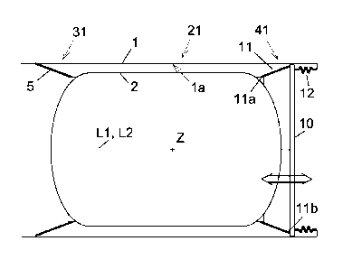
Fig. 6 shows a container arrangement 21 comprising the outer container 1 with
a longitudinal
axis Li and the inner container 2 with a longitudinal axis L2, which is
mounted for thermal
insulation in the outer container I. The two containers 1, 2 are arranged
coaxially to each
other and interconnected by a suspension system comprising the above-described
fixed
bearing 31 and, in addition, a floating bearing 41. The floating bearing 41
has a floating
bearing ring 10 which is made of a rigid material such as a fibre-reinforced
synthetic
material or metal or, respectively, metal alloys and is mounted so as to be
axially
displaceable (see double arrow) along the inner wall la of the outer container
I. Floating
bearing securing elements 11, which can be stressed in tension and in
compression, engage,
on the one hand, the floating bearing ring 10 and, on the other hand, the
inner container 2,
while being distributed annularly. The floating bearing ring 10 is prestressed
by means of
tension springs 12 engaging the outer container 1 directly or indirectly. From
a geometric
point of view (analogously to the illustration of Fig. 2), the floating
bearing securing
elements 11 are arranged in an annular installation space extending
essentially around the
circumference of the inner container 2. The floating bearing securing elements
11 are
manufactured from a material as rigid as possible. Very suitable are fibre-
reinforced
materials, preferably comprising aramide fibres, carbon fibres, glass fibres,
basalt fibres or
combinations thereof, particulary preferably comprising aramide fibres which,
in sections,
are mixed with glass fibres.
The floating bearing securing elements 11 are oblique to the longitudinal axis
L2 of the inner
container 2 and are mirrored, always in pairs, at a plane including the
longitudinal axis L2 of
the inner container. The contact points lla of the floating bearing securing
elements 11 at
the inner container 2 are closer to the centre Z of the inner container 2 than
the contact points
llb of the securing elements 11 at the floating bearing ring 10.
Fig. 7 shows a variant of a container arrangement 22 comprising the outer
container 1 and
the inner container 2 mounted for thermal insulation in the outer container 1.
In said variant,
the suspension system, which interconnects the two containers 1, 2, comprises
the fixed
CA 02908324 2015-09-29
13
bearing 32 as described above on the basis of Fig. 4 and, in addition, a
variant of a floating
bearing 42 in which ¨ unlike in Fig. 6 ¨ the floating bearing ring 10 is
arranged above the
inner container 2 and is pre-biased by compression springs 13 engaging the
outer container 1
directly or indirectly. The floating bearing securing elements 11 engage, on
the one hand, the
floating bearing ring 10 and, on the other hand, the front wall 2b of the
inner container 2 in
proximity to the circumference, while being distributed annularly. The
floating bearing
securing elements 11 are oblique to the longitudinal axis L2 of the inner
container 2. The
contact points lla of the floating bearing securing elements 11 at the inner
container 2 are,
from an axial point of view, further away from the centre Z of the inner
container 2 than the
contact points 1lb of the securing elements 11 at the floating bearing ring
10.
Fig. 8 shows an embodiment of a container arrangement 23, wherein the inner
container 2' is
configured as a cuboid with rounded edges and the outer container l' is
likewise configured
as a cuboid with rounded edges. The outer container l' has a longitudinal axis
L I and the
inner container 2' has a longitudinal axis L2. The two containers are rigidly
connected to
each other by a fixed bearing 34, wherein the rigid fixed bearing securing
elements 5' are
designed as framework elements of a frame structure which are oblique to the
longitudinal
axis L2 of the inner container 2' and are neither parallel nor normal to the
longitudinal axis
L2 of the inner container 2. The fixed bearing securing elements 5' are
mirrored, always in
pairs, at a plane including the longitudinal axis L2 of the inner container
and are skew
relative to the longitudinal axis L2 of the inner container. This frame
structure can be
manufactured easily from a fibre-reinforced synthetic material, e.g., by
milling or punching a
plate. It should be mentioned that an equivalent frame structure can be
implemented also for
the floating bearing.
In Fig. 9A and Fig. 9B, a particularly advantageous embodiment of a floating
bearing 43 is
illustrated, wherein the floating bearing securing elements 11 are connected
to the inner
container 2 and the floating bearing ring 10 in a geometric installation space
which is
roughly cylindrical. Said embodiment provides the major advantage that, in
case of a
dynamic load FD which is transverse to the longitudinal axis L2, the inner
container 2 will
indeed be deflected in the direction of the dynamic load (reference symbol D),
but, due to the
roughly cylindrical installation space, the deflection D will lead to
practically no inclination
of the floating bearing ring 10, as can be seen in Fig. 9B.
In Figs. 10A and 10B, a fixed bearing 35 equivalent to Fig. 1 is illustrated
in a front view
and in an isometric view. The contact points 5b of the fixed bearing securing
elements 5 are
located on a peripheral circle at the inner wall 1 a of the outer container 1,
while being
CA 02908324 2015-09-29
14
distributed annularly. The contact points 5a of the fixed bearing securing
elements 5 are
located at the inner container 2 on a circle defined at the outer wall 2a. The
fixed bearing
securing elements 5 are oblique to the longitudinal axis L2 of the inner
container 2, the
longitudinal axis L2 including the centre Z, and are mirrored, always in
pairs, at a plane
including the longitudinal axis L2 of the inner container, see, e.g., plane x.
Said arrangement
is feasible also by a framework structure such as that illustrated in Fig. 8
in that the
individual fixed bearing elements 5 are replaced by the securing elements 5'
in the form of
framework elements which are integrated in a framework frame structure. To
that effect, the
schematic embodiments of Figs. 1 to 7 as well as Figs. 9A, 9B are also
feasible by a
framework structure having integrated securing elements 5' in the form of
framework
elements.
Fig. 11 shows an embodiment similar to Fig. 8 of a container arrangement 24,
wherein the
inner container 2' is configured as a cuboid with rounded edges and the outer
container l' is
likewise configured as a cuboid with rounded edges. The outer container 1'
surrounds the
inner container 2' at a distance and extends beyond the inner container 2'.
The outer
container l' has a longitudinal axis LI and the inner container 2' has a
longitudinal axis L2.
The two longitudinal axes LI, L2 are coaxial and extend in the main dimension
of the
containers l', 2'. The two containers are rigidly connected to each other by a
fixed bearing
36, wherein the rigid fixed bearing securing elements 5" are designed as
plates of a frame
structure which are oblique, i.e., not normal, to the longitudinal axis L2 of
the inner
container 2'. This frame structure can be manufactured easily from a fibre-
reinforced
synthetic material, e.g., by milling or punching and bending a plate. It
should be mentioned
that an equivalent frame structure can be implemented also for the floating
bearing.
Fig. 12 shows an embodiment similar to Fig. 11 of a container arrangement 25,
wherein the
inner container 2' is configured as a cuboid with rounded edges and the outer
container l' is
likewise configured as a cuboid with rounded edges. The outer container l'
surrounds the
inner container 2' at a distance and extends beyond the inner container 2'.
The outer
container l' has a longitudinal axis Li and the inner container 2' has a
longitudinal axis L2.
The two longitudinal axes LI, L2 are coaxial and extend in the main dimension
of the
containers l', 2'. The two containers are rigidly connected to each other by a
fixed bearing
37, wherein the rigid fixed bearing securing elements 5" are designed as
plates which are
oblique, i.e., not normal, to the longitudinal axis L2 of the inner container
2'. It should be
mentioned that also the floating bearing can be implemented by means of plate-
shaped
floating bearing securing elements.
CA 02908324 2015-09-29
Fig. 13 shows a container arrangement 26, wherein the inner container 2 is
designed
cylindrically and the outer container 1 is likewise designed cylindrically.
The outer container
1 surrounds the inner container 2 at a distance and extends beyond the inner
container 2. The
outer container 1 has a longitudinal axis Li and the inner container 2 has a
longitudinal axis
L2, which are coaxial and extend in the main dimension of the containers 1, 2.
The two
containers 1, 2 are rigidly connected to each other by a fixed bearing 38,
wherein the rigid
fixed bearing securing elements 5" are designed as plates of a frame structure
which are
oblique, i.e., not normal, to the longitudinal axis L2 of the inner container
2. This frame
structure can be manufactured easily from a fibre-reinforced synthetic
material, e.g., by
milling or punching and bending a plate. An equivalent frame structure can be
implemented
also for the floating bearing. The fixed bearing securing elements 5" are
arranged radially in
the installation space between the outer container 1 and the inner container 2
and are
distributed evenly across the circumference. As a matter of principle, the
radial arrangement
of the fixed bearing securing elements 5" has a lower rigidity against torsion
of the outer
container 1 relative to the inner container 2, which, however, is compensated
for by the plate
shape of the fixed bearing securing elements 5".
Fig. 14 shows an embodiment similar to Fig. 13 of a container arrangement 27,
which differs
basically only in that the rigid fixed bearing securing elements 5" of the
fixed bearing 39
are designed as plates which are connected directly, without a frame
structure, to the outer
container 1 and the inner container 2.
In the embodiments of Figs. 11 to 14, the plate-shaped fixed bearing securing
elements 5",
5" are arranged such that they are able to absorb substantial shearing forces.
If, for
example, a vertical force acts upon the inner container 1, l', the fixed
bearing securing
elements which are oriented essentially vertically and are arranged in the
drawing on the left
and on the right will take the main load, thereby transmitting shearing
forces. The fixed
bearing securing elements which are arranged essentially horizontally would be
subjected
slightly to bending stress, however, they do not transmit particularly large
forces.
Fig. 15 shows a container arrangement 21' similar to Fig. 6 comprising the
outer container 1
with a longitudinal axis Ll and the inner container 2 with a longitudinal axis
L2, which is
mounted for thermal insulation in the outer container 1. The two containers 1,
2 are arranged
coaxially to each other and are interconnected by a suspension system
comprising the above-
described fixed bearing 31 and, in addition, a floating bearing 44. The
floating bearing 44
has a floating bearing ring 10' made of a rigid material such as a fibre-
reinforced synthetic
material or metal or, respectively, a metal alloy. Floating bearing securing
elements 11',
CA 02908324 2015-09-29
16
which can be stressed in tension and in compression, engage, on the one hand,
the floating
bearing ring 10' with contact points ii a' and, on the other hand, the outer
container 1 via
contact points llb', while being distributed annularly, and thus keep the
floating bearing
ring 10' in a defined position. The inner container 2 is arranged displaceably
in the floating
bearing ring 10' (symbolized by a double arrow), wherein, in said embodiment,
a cylindrical
appendage of the inner container 2 is mounted displaceably in the floating
bearing ring 10'.
The inner container 2 is prestressed by tension springs 12 engaging the inner
container 2 and
the floating bearing ring 10'. The floating bearing securing elements 11' are
manufactured
from a material as rigid as possible. Very suitable are fibre-reinforced
materials, preferably
comprising aramide fibres, carbon fibres, glass fibres, basalt fibres or
combinations thereof,
particulary preferably comprising aramide fibres which, in sections, are mixed
with glass
fibres. The contact points 11 b' of the floating bearing securing elements 11'
at the outer
container 1 are axially further away from the centre Z of the inner container
2 than the
contact points 11 a' of the floating bearing securing elements 11' at the
floating bearing ring
10'.
Fig. 16 shows a further embodiment of a container arrangement 22' according to
the
invention which is similar to the embodiment of Fig. 12, but differs therefrom
in a design of
the fixed bearing 32 as described above on the basis of Fig. 7 and in a
variant of the floating
bearing 45. The floating bearing 45 has a floating bearing ring 10' made of a
rigid material
such as a fibre-reinforced synthetic material or metal or, respectively, a
metal alloy. Floating
bearing securing elements 11', which can be stressed in tension and in
compression, engage,
on the one hand, the floating bearing ring 10' with contact points I la' and,
on the other
hand, the outer container 1 via contact points llb', while being distributed
annularly, and
thus keep the floating bearing ring 10' in a defined position. The inner
container 2 is
arranged displaceably in the floating bearing ring 10' with an appendage
(symbolized by a
double arrow). The inner container 2 is prestressed by compression springs 13
engaging the
inner container 2 and the floating bearing ring 10'. The contact points ha' of
the floating
bearing securing elements 11' at the floating bearing ring 10' are axially
further away from
the centre Z of the inner container 2 than the contact points 11 b' of the
floating bearing
securing elements 11' at the outer container 1.
Fibre-reinforced parts can normally be stressed in tension more than in
compression. The
tension springs 12 and the compression springs 13 serve for factoring in those
different load
capacities in tension and in compression.
CA 02908324 2015-09-29
17
It should be mentioned that the embodiments of the fixed bearings and the
floating bearings
according to Fig. 15 and Fig. 16 can be implemented also with fixed bearing
securing
elements and with floating bearing securing elements which are designed as
framework
elements of a frame structure or as plates or as plates of a frame structure.