Note: Descriptions are shown in the official language in which they were submitted.
CA 02909142 2015-10-08
SPECIFICATION
INDUSTRIAL FABRIC OF DOUBLE WARPS-SINGLE WEFT TYPE
TECHNICAL FIELD OF THE INVENTION
[ 0 0 1]
The present invention relates to an industrial fabric of double warps-single
weft type
which is capable of improving a surface smoothness, a rigidity, an wear
resistance and
dehydration characteristics by adopting a structure in which an auxiliary weft
other than
wefts woven with upper surface side warps and lower surface side warps is
arranged, in
particular, relates to a fabric for manufacturing unwoven fabric. In addition,
the present
invention relates to an industrial fabric of double warps-single weft type
which is capable of
improving an anti-dirt characteristics by adopting yarns formed by fluorine
resin on the
upper surface, in particular, relates to a fabric for manufacturing unwoven
fabric.
BACKGOUND ART
[ 0 0 2]
Conventionally, an industrial fabric woven by wefts and warps has been used
for a
transporting or filtering application in a manufacturing process of papers,
unwoven fabric,
building material, etc.. For instance, many kinds of industrial fabrics, such
as the fabric for
manufacturing unwoven fabric, the fabric for hydrating sludge, the belt for
manufacturing
the building material, the conveyor belt, and the filtering cloth are widely
known. Such
industrial fabric needs to possess a high rigidity, a permeability, a good
dimension stability,
an wear resistance, and anti-dirt characteristics, etc. for any applications.
More specifically, the high rigidity is required in order to hold and
transport an object
such as material, flotation material component, etc.. In particular, in case
of the
manufacturing process of the building material, or the filtering process under
a severe
environment, the high rigidity is essential for the fabric which deals with
the heavy
material or the flotation material component. Further, the dimension stability
is needed in
order to constantly run the fabric in a stable manner. In addition, in order
to always supply
products of papers, unwoven fabric, or the building material with stable
quality, the
anti-dirt characteristics is important for efficient filtering and
transportation.
[ 0 0 0 3
In particular, the anti-dirt characteristics of the fabric is important for an
air raid
process which is one of the processes of manufacturing unwoven fabric, since
it is closely
associated with the problem of adhesion of fibers. Here, the air raid process
is the process
in which pulp sheet and synthetic fibers of short fibers are dispersed in air
to be formed on
a wire. If the permeability of the fabric is deteriorated, it becomes
technically difficult to
effect the air raid process efficiently.
In addition, the fabric with a sufficient surface smoothness as to make a
transfer of wire
mark of the fabric to the unwoven fabric difficult, and the fabric which is
capable of keeping
the conditions required for manufacturing a good unwoven fabric, for a long
time have been
desired in the art. Further, the fiber supportability, the yield of the
unwoven fabric, and the
running stability have been required. In particular, since the speed at which
the
manufacturing machine is run has recently become high, the request for the
fabric used for
1
CA 02909142 2015-10-08
the transportation has become severe.
0 0 41
The problems of the surface smoothness arises at a location where the upper
surface side
warp and the weft are woven with each other. For instance, in a case where the
diameter of
5 the
fiber of the weft which is woven with the upper surface side warp and the
lower surface
side warp increases, the concave marl arises on the surface of the paper by
the knuckle of
the upper surface side warp passing above the weft. On the other hand, in a
case where the
diameter of the fiber of the weft which is woven with the upper surface side
warp and the
lower surface side warp decreases, since the rigidity of the weft is
deteriorated to largely
10
influence on the rigidity of the fiber, the durability of the product of the
fabric is shortened.
In particular, if the weft woven with the upper surface side warp and the
lower surface
side warp gets worn or cut, the product life of the fabric ends.
10 0 0 51
Recently, yarns and resin material with a view to attain the anti-dirt effect
have been
developed, in particular. For instance, in a fabric for unwoven fabric in
Patent Publication 1,
the upper surface side fabric is constituted by yarns including an anti-dirt
function such as
fluorine resin, more specifically, the ones by blending fluoro polymer such as
copolymer of
ethylene- tetrafluoroethylene ( referred to as " ETFE " hereinafter ) and
dicarboxylic acid
in aromatic series such as polyethylene terephthalate ( referred to as " PET "
hereinafter),
while the lower surface side fabric is constituted by normal yarns such as PET
in order to
fulfill the required physical properties such as rigidity. As described above,
the material of
the yarns for the upper surface side and that for the lower surface side have
been adopted
in a distinguished manner.
If double wefts vertically overlapped with each other are adopted as binding
yarns in
such two-layered fabric for unwoven fabric, since the weft forms the knuckle
on the upper
surface side, the yarns formed by PET with poor anti-dirt effect are exposed
on the surface
of the fabric, so that the anti-dirt effect caused by the upper surface side
fabric of fluorine
resin are not sufficiently obtained.
In order to solve such technical problems, if the number of the wefts are
decreased, the
rigidity of the fabric gets decreased. That is why the technology for
improving the surface
smoothness by increasing the density of the warps so as to increase the number
of the
knuckles by the warps on the fabric surface has been required.
[ 0 0 0 61
Patent Publication 1: WO/2012/140993
Patent Publication 2: Japanese Patent No.3938817
DISCLOSURE OF THE INVENTION
TECHNICAL PROBLEMS TO BE SOLVED BY PRESENT INVENTION
1000 71
An object of the present invention is to provide an industrial fabric which is
capable of
improving a surface smoothness by restricting a formation of a knuckle by
wefts on a fabric
surface. Another object of the present invention is to provide an industrial
fabric of a double
2
warps-single weft type which is capable of improving a rigidity, an wear
resistance, and a
permeability. An object of the present invention is to provide an industrial
fabric which is
capable of controlling an on-stack structure of an upper surface side warp and
lower surface
side warp. An object of the present invention is to provide an industrial
fabric which is
capable of improving an anti-dirt effect on the upper surface side and
lengthening the
durability of a product, while at the same time of keeping the strength of
weaving the upper
surface side and the lower surface side, in a case where yarns exposed to the
upper surface
side are formed by the ones which include an anti-dirt effect such as fluorine
resin.
MEANS TO SOLVE TECHNICAL PROBLEMS
[ 0 0 0 8 ]
In order to solve the above technical problems, the present inventor adopted
the following
structure.
1. An industrial fabric, having upper surface side warps and lower
surface side warps
which are woven by a plurality of wefts, the industrial fabric comprising an
auxiliary weft between the plurality of wefts, wherein the auxiliary weft is
arranged between the upper surface side warps and the lower surface side
warps,
and wherein none of the upper surface side warps goes under the auxiliary weft
and none of the lower surface side warps goes over the auxiliary weft.
2. The industrial fabric according to 1, wherein upper side floating yarns are
arranged
above the plurality of wefts so as to be woven with the upper surface side
warp only.
3. The industrial fabric according to 1 or 2, wherein upper side floating
yarns are
arranged below the plurality of wefts so as to be woven with the lower surface
side
warp only.
[ 0 0 0 9 ]
4. The industrial fabric according to any of 1 to 3, wherein a diameter of the
auxiliary
weft is set to be larger than that of the plurality of wefts.
5. The industrial fabric according to any of 2 to 4, wherein the upper
surface side warp
and the upper surface side floating yarn are made of fluorine resin, and the
plurality
of wefts is constituted by yarns made of material other than fluorine resin.
6. The industrial fabric according to any of 2 to 5, wherein a location
ratio of the upper
surface side floating yarn and/or the lower surface side floating yarn to the
plurality of
wefts is 1:1.
[ 0 0 1 ]
EFFECT OF THE INVENTION
According to the industrial fabric of double warps-single weft woven type of
the present
invention, a surface smoothness can be improved by restricting a formation of
a knuckle by
wefts on a fabric surface. In addition, a rigidity, an wear resistance, and a
permeability can
be improved. Further, an on-stack structure of an upper surface side warp and
lower
surface side warp can be controlled. Still further, an anti-dirt effect on the
upper surface
3
Date Recue/Date Received 2020-06-05
CA 02909142 2015-10-08
side can be improved and the durability of a product can be lengthened, while
at the same
time, the strength of weaving the upper surface side and the lower surface
side is kept, in a
case where yarns exposed to the upper surface side are formed by the ones
which include
an anti-dirt effect such as fluorine resin.
0 0 1 11
BRIEF EXPLANATION OF DRAWINGS
Fig.1 is a design view showing a complete structure of the first embodiment
according to
the present invention.
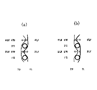
Fig.2 is a cross section view taken along the warp of the first embodiment.
Fig. 2(a) is a cross section view taken along 1U and 1L in Fig.1.
Fig. 2(b) is a cross section view taken along 2U and 2L in Fig. 1.
[ 0 0 1 2
DETAILED DESCRIPTION OF THE INVENTION
Now, the structure and the effect of the industrial fabric of double warps-
single weft
woven type of the present invention will be described below. Embodiments of
the industrial
fabric of the present invention will be described thereafter with reference to
the drawings.
The technical feature of the industrial fabric of double warps-single weft
woven type of
the present invention is that the upper surface side warp and the lower
surface side warp
are laminated to be woven by a plurality of wefts. The density of the warp can
be increase
by adopting double warps-single weft woven type as a fundamental structure of
the
industrial fabric. Based on this, the surface smoothness can be highly
improved by the fact
that the knuckles emerging on the surface of the fabric are formed by the
upper surface
side warp and the number of the knuckles is increased.
In addition, according to the industrial fabric of double warps-single weft
woven type of
the present invention, the auxiliary weft is arranged between the adjacent
wefts. The
technical feature of the auxiliary weft is that the auxiliary wefts are kept
arranged
between the upper surface side warp and the lower surface side warp without
the upper
and lower surface warps being woven with each other between the adjacent
wefts.
Although the surface smoothness can be highly improved by adopting double
warps-single
weft woven type as a fundamental structure of the industrial fabric, the
rigidity is
decreased. In order to solve such a technical problem, the specific auxiliary
wefts are kept
arranged between the upper surface side warp and the lower surface side warp
without the
upper and lower surface warps being woven with each other between the adjacent
wefts.
The rigidity same as that of the conventional fabric of double-wefts type can
be obtained by
such specific auxiliary wefts.
[ 0 0 1 3]
Further, in the industrial fabric of double warps-single weft woven type of
the present
invention, upper side floating yarns may be arranged above the weft so as to
be woven with
the upper surface side warp only. In the industrial fabric of the present
invention, material
with an excellent rigidity such as PET is adopted as the wefts in order to
improve the
rigidity. While on the other hand, a technical problem in which the wefts
emerge on the
surface of the fabric is raised. By arranging the upper side floating yarns
above the weft,
4
CA 02909142 2015-10-08
such a technical problem is solved, in other words, the wefts are prevented
from emerging
on the surface of the fabric.
Still further, in the industrial fabric of double warps-single weft woven type
of the
present invention, lower side floating yarns may be arranged below the weft so
as to be
woven with the lower surface side warp only. By contacting such floating yarns
with the
upper surface side warps and/or the lower surface side warps, the shift of the
warps can be
controlled so as to adjust the positions at which the upper and lower warps
are overlapped
with each other, whereby the on-stack structure of the upper and lower warps
can be
controlled.
Still further, in the industrial fabric of double warps-single weft woven type
of the
present invention, the diameter of the auxiliary weft may be set to be larger
than that of
the weft. By making the diameter of the auxiliary weft large, the degree of
the exposure of
the warp on the surface can be largely increased. In addition, the rigidity of
the fabric can
be largely increased by adopting the auxiliary weft with the large diameter.
Further, the
wefts are bound inside, even if the upper surface side floating yarns are not
used, by
adopting the auxiliary weft with the large diameter. Still further, the shift
of the upper and
lower warps can be controlled, whereby the on-stack structure of the upper and
lower
warps can be controlled by adopting the auxiliary weft with the large
diameter.
r 0 0 1,411
The upper surface side warps and the upper surface side floating yarns may be
preferably formed by fluorine resin, and the weft may be preferably formed by
yarns made
of material other than fluorine resin.
By adopting such a structure, since yarns emerging on the surface can be
formed by
fluorine resin with excellent anti-dirt characteristic, anti-dirt effect can
be sufficiently
obtained. In addition, since the number of relatively expensive yarns made of
fluorine resin
in the lateral direction can be decreased, the cost of manufacturing the
fabric can be
lowered.
Further, by adopting such a structure, the wefts with the binding function can
be formed
by yarns with higher strength than that of fluorine resin, such as PET. The
inner binding
in which the binding yarns are not exposed on the surface by adopting the
wefts as the
binding yarns. In other words, the yarns such as PET can be prevented from
being exposed
on the surface of the upper surface side fabric formed by only fluorine resin.
The fluorine resin which is material for the upper surface side warps and the
upper
surface side wefts of the fabric of the present invention may be preferably
composite resin
containing fluorine with high anti-dirt. For instance, at least one material
can be selected
from a group of polytetrafluoroethylene (PTFE), copolymer of
tetrafluoroethylene and
hexafluoropropylene (FEP), copolymer of tetrafluoroethylene and fluoro vinyl
ether (PFA),
polyvinylidene fluoride (PVDF), copolymer of ethylene and tetrafluoroethylene
(ETFE),
and copolymer of ethylene and chlorotrifluoroethylene (ECTFE). In particular,
ETFE is
suitable for the anti-dirt characteristics and cost.
In this connection, it is preferable to impregnate silicon resin in the
fluorine resin
material (water dispersion) in order to improve the flexibility. In addition,
the color of the
5
CA 02909142 2015-10-08
surface of the fabric can be freely changed by adding various kinds of pigment
to the
fluorine resin material (water dispersion).
r 0 0 1 5]
The material of the yarns other than fluorine resin used for the wefts of the
industrial
fabric of the present invention can be freely selected in accordance with the
characteristics
desired for the industrial fabric, and is not limited to the specific
material.
The configuration of the yarn includes, in addition to monofilaments,
multifilaments,
spun yarns, finished yarns subjected to crimping or bulking such as so-called
textured yarn,
bulky yarn and stretch yarn, taslan yarns, mole yarns, and yarns obtained by
intertwining
them. As the cross-section of the yarn, not only circular form but also square
or short form
such as stellar form, or elliptical or hollow form can be used. The material
of the yarn can
be selected freely and usable examples of it include polyester, polyamide,
polyphenylene
sulfide, polyvinylidene fluoride, polypropylene, aramid, polyether ketone,
polyethylene
naphthalate, cotton, wool and metal. Of course, yarns obtained using
copolymers or
incorporating or mixing the above-described material with a substance selected
depending
on the intended purpose may be used.
In particular, in a case where spun yarns, processed yarns such as crimping or
bulking,
or the flexible yarns with a large diameter such as mole yarn, for the upper
layer weft is
used, the upper layer surface tends to be covered by theses yarns, so that the
difference of
the appearance between the bonding portion and the ordinary portion can be
hardly
distinguished from each other, from the upper layer side.
[ 0 1 6 ]
The material of the yarns other than fluorine resin used for the wefts of the
industrial
fabric of the present invention can be freely selected in accordance with the
characteristics
desired for the industrial fabric, and is not limited to the specific
material.
The configuration of the yarn includes, in addition to monofilaments,
multifilaments,
spun yarns, finished yarns subjected to crimping or bulking such as so-called
textured yarn,
bulky yarn and stretch yarn, and yarns obtained by intertwining them. As the
cross-section
of the yarn, not only circular form but also square or short form such as
stellar form, or
elliptical or hollow form can be used. The material of the yarn can be
selected freely and
usable examples of it include polyester, polyamide, polyphenylene sulfide,
polyvinylidene
fluoride, polypropylene, aramid, polyether ketone, polyethylene naphthalate,
polytetrafluoroethylene, cotton, wool and metal. Of course, yarns obtained
using
copolymers or incorporating or mixing the above-described material with a
substance
selected depending on the intended purpose may be used.
Since the yarn constituting the fabric for unwoven fabric generally includes a
high
rigidity, polyester monofilaments with excellent dimension stability may be
preferably
adopted.
[ 0 1 71
Further, in the industrial fabric of the present invention, the ratio of the
arrangement of
the upper surface side floating yarn and/or the lower surface side floating
yarn to the weft
may preferably be set to be 1:1. The shift of the warp can be restricted by
adopting such a
6
CA 02909142 2015-10-08
structure to cause the warp to contact the floating yarn. In particular, the
looseness of the
warp can be fully controlled by sandwiching a single weft between a single
upper surface
side floating yarn and a single lower surface side floating yarn.
[ 0 0 1 81
Now, the embodiments of the present invention will be described below with
reference to
the drawings. Fig.1 is the conceptual plain view showing the complete
structure of the first
embodiment 1. The industrial fabric of the first embodiment is the one for
unwoven fabric.
Here, the design view corresponds to the complete structure of the fabric
defining the
minimum unit to be repeated of the fabric structure. The fabric recited in the
claims
corresponds to this complete structure. The final product is completed by
combining any
number of such complete structures in the longitudinal direction and the
direction
perpendicular to the longitudinal direction.
In each of the design views, the warp is indicated by a reference number such
as 1,2,
while the weft is indicated by a reference number such as l', ........... 4'.
The upper and lower
warps are indicated by the reference number to which U and L are attached,
respectively.
The weft which functions as the binding yarn is indicated by adding W, such as
2'W.
Further, the auxiliary weft is indicated by S, while, the floating yarn is
indicated by f.
In each of the design views, a symbol ")<" indicates that the upper surface
side warp is
arranged above the upper surface side weft to form a knuckle on the surface of
the fabric,
and a symbol "0" indicates that the lower surface side warp is arranged below
the weft. A
solid square symbol "II" indicates that the upper surface side floating yarn
is arranged
above the upper surface side warps to form a knuckle on the surface of the
fabric, and an
open square symbol "El" indicates that the lower surface side floating yarn is
arranged
below the lower surface side warps.
The upper surface side warps and the lower surface side warps are overlapped
in the
vertical direction to form an on-stack structure.
100 1 91
As shown in Fig.1, in the industrial fabric for the unwoven fabric of double
warps-single
weft woven type of the present invention, the upper surface side warps (1U,20
and the
lower surface side warps (1420 are laminated in the vertical direction. Such
upper and
lower surface side warps are woven with a plurality of wefts (2'W, 4'W).
Auxiliary wefts (1'S,3'S) are arranged between the adjacent wefts (2'W,
4'W)and kept
located between the upper surface side warps (1U,2U) and the lower surface
side warp
(1420 without being woven with the upper and lower surface side warps.
As shown in Fig.2(a), in the industrial fabric for the unwoven fabric of
double
warps-single weft woven type of the present invention, upper surface side
floating yarns
(2'Uf, 4'Uf ) are arranged above the wefts (2'W, 4'W) with being woven with
the upper
surface side warp (11.1) only. In addition, the upper surface side warp (1U)
passes over the
upper surface side floating yarn (2'Uf ) and passes under the upper surface
side floating
yarn (4'Uf ). Further, the upper surface side warp (10 passes under the weft
(4'W). The
lower surface side warp (10 passes above the weft (2'W). Still further, lower
surface side
floating yarns (2'Lf, 4'Lf ) are arranged below the wefts (2'W, 4'W) with
being woven with
7
CA 02909142 2015-10-08
the lower surface side warp (1L) only.
'I 0 0 2 0
As shown in Fig.2(a), in the industrial fabric for the unwoven fabric of the
first
embodiment 1, the diameter of each of the auxiliary wefts (1'S,3'S) is set to
be larger than
that of each of the wefts (2'W, 4'W). The degree of the exposure of the warp
on the surface
largely increases by adopting such a structure, whereby the rigidity of the
fabric increases,
so that the shift of the upper and power warps can be restricted.
As shown in Fig.2(b), in the industrial fabric for the unwoven fabric of
double
warps-single weft woven type of the present invention, upper surface side
floating yarns
(2'Uf, 4'Uf ) are arranged above the wefts (2'W, 4'W) with being woven with
the upper
surface side warp (2U) only. In addition, the upper surface side warp (2U)
passes under the
upper surface side floating yarn (2'Uf ) and passes above the upper surface
side floating
yarn (4'Uf ). Further, the upper surface side warp (2U) passes under the weft
(2'W). The
lower surface side warp (2L) passes above the weft (4'W). Still further, lower
surface side
floating yarns (2'Lf, 4'Lf ) are arranged below the wefts (2'W, 4'W) with
being woven with
the lower surface side warp (2L) only.
Still further, lower surface side floating yarns (2'Lf, 4'Lf ) are arranged
below the wefts
(2'W, 4'W) with being woven with the lower surface side warp (2L) only.
1002 11
Such being the case, the rigidity same as that of the conventional double-
wefts type can
be obtained by arranging the auxiliary wefts (1'S,3'S) between the adjacent
wefts (2'W,
4'W).
Here, the ratio of arrangement of the upper surface side floating yarn and the
lower
surface side floating yarn to the weft is set to be 1:1. The technical problem
in which the
wefts (2'W, 4'W) emerge on the surface of the fabric can be solved by
arranging the upper
surface side floating yarns (2'Uf, 4'Uf ) above the wefts (2'W, 4'W).
In the fabric for unwoven fabric of the first embodiment, the density of the
knuckles can
be increased to improve the surface smoothness by forming the knuckles
emerging on the
surface by means of the upper surface side warps (1U,20 only.
[ 0 0 2 2 ]
EXPLANATION OF SYMBOLS
1U, 2U : upper surface side warp
1L, 2L lower surface side warp
2 'W, 4 'W :weft
1 ' S, 3 ' S : auxiliary weft
2' Uf, 4 'Uf : upper surface side floating yarn
2' Lf, 4 'Lf : lower surface side floating yarn
8