Note: Descriptions are shown in the official language in which they were submitted.
CA 02909284 2016-05-17
-1-
DESCRIPTION
FUEL CELL SYSTEM WITH ESTIMATE OF
CURRENT/VOLTAGE CHARACTERISTICS DURING WARM-UP
TECHNICAL FIELD
[0001] The present invention relates to a fuel cell system and a control
method for fuel cell system.
BACKGROUND ART
[0002] JP2000-357526A discloses a conventional fuel cell system in which
a current-voltage characteristic of a fuel cell is estimated on the basis of
an
output voltage detected while an output current of the fuel cell is changed.
SUMMARY OF INVENTION
[0003] After the start-up of a fuel cell system, a fuel cell is warmed up
by
driving an auxiliary machine with generated power of the fuel cell and a
vehicle
travel permit is issued after an IV characteristic of the fuel cell reaches a
desired IV characteristic. Thus, it is being studied to issue the vehicle
travel
permit as early as possible by estimating the IV characteristic during the
warm-up of the fuel cell and issuing the vehicle travel permit when the
estimated IV characteristic reaches the desired IV characteristic.
[0004] However, in order to ensure the estimation accuracy of the IV
characteristic, the IV characteristic needs to be estimated on the basis of an
output voltage when an output current of the fuel cell is changed with a
specified current width or larger. Thus, if the output current of the fuel
cell is
suddenly increased by the current width to accurately estimate the IV
characteristic during the warm-up in which power generation becomes
unstable due to water or ice in the fuel cell, a voltage drop may occur due to
CA 2909284 2017-05-31
-2-
such a sudden current change.
[0005] On the other hand, if it is attempted to estimate the IV
characteristic
on the basis of the output voltage when the output current of the fuel cell is
gradually increased to prevent such a voltage drop, the IV characteristic
desired to be estimated may change during the rise of the output current and
it
may be impossible to ensure estimation accuracy since the IV characteristic
changes from moment to moment during the warm-up of the fuel cell.
[0006] The present invention was developed in view of such a problem and
aims to ensure the estimation accuracy of an IV characteristic while
suppressing the occurrence of a voltage drop.
[0007] According to one aspect of the present invention, a fuel cell system
for generating power by supplying anode gas and cathode gas to a fuel cell is
provided. The fuel cell system also includes an auxiliary machine to be
connected to the fuel cell, warm-up power control means for controlling
generated power of the fuel cell by adjusting power supplied to the auxiliary
machine during the warm-up of the fuel cell, and IV characteristic estimation
means for temporarily reducing the power supplied to the auxiliary machine
and estimating an IV characteristic of the fuel cell on the basis of at least
two
pairs of current values and voltage values at that time during the warm-up of
the fuel cell.
According to another aspect of the present invention, there is provided a
fuel cell system for generating power by supplying anode gas and cathode gas
to a
fuel cell, comprising:
an auxiliary machine for the fuel cell, the auxiliary machine including a
battery for storing surplus power of the fuel cell and an electrical component
to be
driven when the fuel cell generates power;
warm-up power control means for controlling generated power of the fuel
cell by adjusting power to be supplied to the auxiliary machine during the
warm-
up of the fuel cell based on self-heat generation thereof; and
CA 2909284 2017-05-31
-2a-
current/voltage characteristic estimation means for obtaining at least
two pairs of current values and voltage values while temporarily.reducing the
power
supplied to the auxiliary machine during the warm-up of the fuel cell, and the
current/voltage characteristic estimation means estimating a current/voltage
characteristic of the fuel cell based on the at least two pairs of current
values and
voltage values thus obtained.
According to a further aspect of the present invention, there is provided
a control method for a fuel cell system configured to generate power by
supplying
anode gas and cathode gas to a fuel cell and including an auxiliary machine
for the
fuel cell, the auxiliary machine including a battery for storing surplus power
of the
fuel cell and an electrical component to be driven when the fuel cell
generates
power, the control method comprising:
controlling generated power of the fuel cell by adjusting power to be
supplied to the auxiliary machine during the warm-up of the fuel cell based on
self-
heat generation thereof;
obtaining at least two pairs of current values and voltage values while
temporarily reducing the power supplied to the auxiliary machine during the
warm-up of the fuel cell, and
estimating a current/voltage characteristic of the fuel cell based on the
at least two pairs of current values and voltage values thus obtained.
BRIEF DESCRIPTION OF DRAWINGS
[0008] FIG. 1 is a schematic diagram of a fuel cell system according to one
embodiment of the present invention,
FIG. 2 is a graph showing a relationship between the temperature of a
fuel cell stack and a current-voltage characteristic of the fuel cell stack,
FIG. 3 is a graph showing a method for estimating the IV characteristic of
the fuel cell stack during the start-up of the fuel cell system,
CA 02909284 2015-10-09
-3-
FIG. 4 shows graphs showing a reason for obtaining data while reducing
an output current,
FIG. 5 is a control block diagram for setting a target output current
according to one embodiment of the present invention,
FIG. 6 is a time chart showing changes of the output current and
generated power controlled by the control block diagram of FIG. 5,
FIG. 7 is a flow chart showing an IV characteristic estimation control
according to one embodiment of the present invention,
FIG. 8 is a flow chart showing a transient-state IV characteristic
estimation process, and
FIG. 9 is a flow chart showing a steady-state IV characteristic estimation
process.
DESCRIPTION OF EMBODIMENT
[0009] Hereinafter, each embodiment of the present invention is described
with reference to the drawings and the like.
[0010] In a fuel cell, an electrolyte membrane is sandwiched by an anode
electrode (fuel electrode) and a cathode electrode (oxidant electrode) and
power
is generated by supplying anode gas (fuel gas) containing hydrogen to the
anode electrode and cathode gas (oxidant gas) containing oxygen to the
cathode electrode. Electrode reactions which proceed in both anode and
cathode electrodes are as follows.
[0011] Anode electrode: 2H2--->4H++4e- ...(1)
Cathode electrode: 4H++4e-+02-32H20 ... (2)
[0012] The fuel cell generates an electromotive force of about 1 volt by
the
above electrode reactions (1) and (2).
[0013] In the case of using a fuel cell as a power source for automotive
CA 02909284 2015-10-09
-4-
vehicle, a fuel cell stack in which several hundreds of fuel cells are
laminated is
used since required power is large. By configuring a fuel cell system for
supplying the anode gas and the cathode gas to the fuel cell stack, power for
driving a vehicle is taken out.
[0014] FIG. 1 is a schematic diagram of a fuel cell system 100 according to
one embodiment of the present invention.
[0015] The fuel cell system 100 includes a fuel cell stack 1, a cathode gas
supplying/discharging device 2, an anode gas supplying/discharging device 3,
a power system 4 and a controller 5.
[0016] The fuel cell stack 1 is formed by laminating several hundreds of
fuel
cells and generates power necessary to drive a vehicle upon receiving the
supply of the anode gas and the cathode gas. The fuel cell stack 1 includes an
anode electrode side output terminal 11 and a cathode electrode side output
terminal 12 as terminals for taking out power.
[0017] The cathode gas supplying/discharging device 2 is a device for
supplying the cathode gas to the fuel cell stack 1 and discharging cathode
off-gas discharged from the fuel cell stack 1 to outside air. The cathode gas
supplying/discharging device 2 includes a cathode gas supply passage 21, a
filter 22, a cathode compressor 23, a cathode gas discharge passage 24 and a
cathode pressure regulating valve 25.
[0018] The cathode gas supply passage 21 is a passage in which the
cathode gas to be supplied to the fuel cell stack 1 flows. One end of the
cathode gas supply passage 21 is connected to the filter 22 and the other end
is connected to a cathode gas inlet hole of the fuel cell stack 1.
[0019] The filter 22 removes foreign substances in the cathode gas to be
taken into the cathode gas supply passage 21.
[0020] The cathode compressor 23 is provided in the cathode gas supply
CA 02909284 2015-10-09
-5-
passage 21. The cathode compressor 23 takes air (outside air) as the cathode
gas into the cathode gas supply passage 21 via the filter 22 and supplies it
to
the fuel cell stack 1.
[0021] The cathode gas discharge passage 24 is a passage in which the
cathode off-gas discharged from the fuel cell stack 1 flows. One end of the
cathode gas discharge passage 24 is connected to a cathode gas outlet hole of
the fuel cell stack 1 and the other end serves as an opening end.
[0022] The cathode pressure regulating valve 25 is provided in the cathode
gas discharge passage 21. An opening of the cathode pressure regulating
valve 25 is controlled to an arbitrary opening by the controller 5 to adjust a
pressure of the cathode gas to be supplied to the fuel cell stack 1 to a
desired
pressure.
[0023] The anode gas supplying/discharging device 3 is a device for
supplying the anode gas to the fuel cell stack 1 and discharging anode off-gas
discharged from the fuel cell stack 1 to the cathode gas discharge passage 24.
The anode gas supplying/discharging device 3 includes a high-pressure tank
31, an anode gas supply passage 32, a pressure regulating valve 33, an anode
gas discharge passage 34 and a purge valve 35.
[0024] The high-pressure tank 31 stores the anode gas to be supplied to the
fuel cell stack 1 in a high-pressure state.
[0025] The anode gas supply passage 32 is a passage for supplying the
anode gas discharged from the high-pressure tank 31 to the fuel cell stack 1.
One end of the anode gas supply passage 32 is connected to the high-pressure
tank 31 and the other end is connected to an anode gas inlet hole of the fuel
cell stack 1.
[0026] The pressure regulating valve 33 is provided in the anode gas supply
passage 32. The pressure regulating valve 33 is on-off controlled by the
CA 02909284 2015-10-09
-6-
controller 5 to adjust a pressure of the anode gas flowing out to the anode
gas
supply passage 32 from the high-pressure tank 31 to a desired pressure.
[0027] The anode
gas discharge passage 34 is a passage in which the anode
off-gas discharged from the fuel cell stack 1 flows. One end of the anode gas
discharge passage 34 is connected to an anode gas outlet hole of the fuel cell
stack 1 and the other end is connected to the cathode gas discharge passage
24.
[0028] The purge
valve 35 is provided in the anode gas discharge passage
34. The purge
valve 35 is on-off controlled by the controller 5 to adjust a flow
rate of the anode off-gas discharged from the anode gas discharge passage 34
to the cathode gas discharge passage 24.
[0029] The power
system 4 includes a current sensor 41, a voltage sensor
42, a travel motor 43, an inverter 44, a battery 45 and a DC/DC converter 46.
[0030] The current
sensor 41 detects a current extracted from the fuel cell
stack 1 (hereinafter, referred to as an "output current").
[0031] The voltage
sensor 42 detects an inter-terminal voltage between the
anode electrode side output terminal 11 and the cathode electrode side output
terminal 12 (hereinafter, referred to as an "output voltage").
[0032] The travel motor 43 is a three-phase alternating-current
synchronous motor in which a permanent magnet is embedded in a rotor and
a stator coil is wound around a stator. The travel motor 43 has a function as
a motor to be rotationally driven upon receiving the supply of power from the
fuel cell stack 1 and the battery 45 and a function as a generator for
generating
electromotive forces on opposite ends of the stator coil during the
deceleration
of the vehicle in which the rotor is rotated by an external force.
[0033] The
inverter 44 is composed of a plurality of semiconductor switches
such as IGBTs (Insulated Gate Bipolar Transistors). The semiconductor
CA 02909284 2015-10-09
-7-
switches of the inverter 44 are on-off controlled by the controller 5, thereby
converting direct-current power into alternating-current power or
alternating-current power into direct-current power. The inverter 44 converts
composite direct-current power of generated power of the fuel cell stack 1 and
output power of the battery 45 into three-phase alternating-current power and
supplies it to the travel motor 43 when the travel motor 43 functions as the
motor. On the other hand, the inverter 44 converts regenerative power
(three-phase alternating-current power) of the travel motor 43 into
direct-current power and supplies it to the battery 45 when the travel motor
43
functions as the generator.
[0034] The battery 45 is charged with a surplus of the generated power
(output current x output voltage) of the fuel cell stack 1 and the
regenerative
power of the travel motor 43. The power charged into the battery 45 is
supplied to auxiliary machines such as the cathode compressor 23 and the
travel motor 43 if necessary.
[0035] The DC/DC converter 46 is a bidirectional voltage converter for
increasing and decreasing the output voltage of the fuel cell stack 1. By
controlling the output voltage of the fuel cell stack 1 by the DC/DC converter
46, the output current of the fuel cell stack and, consequently, the generated
power are controlled.
[0036] The controller 5 is configured by a microcomputer including a
central processing unit (CPU), a read-only memory (ROM), a random access
memory (RAM) and an input/output interface (I/O interface). Signals from
various sensors necessary to control the fuel cell system 100 are input to the
controller 5. The sensors include an accelerator stroke sensor 51 for
detecting
a depressed amount of an accelerator pedal (hereinafter, referred to as an
"accelerator operation amount"), an SOC sensor 52 for detecting a charged
CA 02909284 2015-10-09
-8-
amount of the battery 45, a battery temperature sensor 53 for detecting a
temperature of the battery 45 besides the current sensor 41 and the voltage
sensor 42 described above.
[0037] FIG. 2 is a graph showing a relationship between the temperature of
the fuel cell stack 1 and a current-voltage characteristic (hereinafter,
referred
to as an "IV characteristic") of the fuel cell stack 1. In FIG. 2, an IV
characteristic shown by solid line is an IV characteristic after the warm-up
of
the fuel cell stack 1 is completed (hereinafter, referred to as a "reference
IV
characteristic").
[0038] As shown in FIG. 2, the IV characteristic of the fuel cell stack 1
changes according to the temperature of the fuel cell stack 1 and the output
voltage when the output current of the same value is extracted from fuel cells
becomes lower as the temperature of the fuel cell stack 1 decreases.
Specifically, the power generation efficiency of the fuel cell stack 1
decreases as
the temperature of the fuel cell stack 1 decreases.
[0039] If the travel of the vehicle is permitted in a state where the power
generation efficiency of the fuel cell stack 1 is low, power required by the
travel
motor 43 during travel increases and the output voltage of the fuel cell stack
1
may fall below a minimum voltage when the output current of the fuel cell
stack 1 increases. Here, the minimum voltage is a voltage value which is set
by an experiment or the like in advance and at which the travel motor 43
cannot be driven if the output voltage of the fuel cell stack 1 falls below
the
minimum voltage.
[0040] Accordingly, after the start-up of the fuel cell system 100, a
vehicle
travel permit needs to be issued after confirming that the IV characteristic
changing from moment to moment according to a temperature increase of the
fuel cell stack 1 by a warm-up of the fuel cell stack 1 has reached an IV
CA 02909284 2015-10-09
-9-
characteristic at which the output voltage of the fuel cell stack 1 does not
fall
below the minimum voltage even if the travel motor 43 is driven. In FIG. 2,
the vehicle travel permit needs to be issued after confirming that the IV
characteristic has been reached an IV characteristic. In this IV
characteristic,
the output voltage at which the output current of the fuel cell stack 1
reaches
a travel permit current does not fall below the minimum voltage. The travel
permit current is a value obtained by adding a predetermined margin to a
minimum value of the output current supposed when the vehicle is caused to
start or travel by driving the travel motor 43 and set by an experiment or the
like in advance.
[0041] However, electrical components energizable during warm-up in
which no travel permit is issued are limited to the auxiliary machines other
than the travel motor 43 such as the cathode compressor 23 and a heater for
heating cooling water for cooling the fuel cell stack 1 and the battery 45.
That
is, an output current not less than a current which can be caused to flow into
the auxiliary machines and the battery 45 cannot be extracted from the fuel
cell stack 1 during warm-up in which no travel permit is issued.
[0042] Accordingly, a maximum value of the output current during
warm-up in which no travel permit is issued (hereinafter, referred to as a
"pre-travel permit maximum current") is the sum of a current which can be
caused to flow into the auxiliary machines (hereinafter, referred to as an
"auxiliary machine consumption current") and a current which can be caused
to flow into the battery 45 (hereinafter, referred to as a "charge current").
This
pre-travel permit maximum current is a value smaller than the travel permit
current.
[0043] Thus, since the travel permit current cannot be extracted from the
fuel cell stack 1 during warm-up in which no travel permit is issued, it is
not
CA 02909284 2015-10-09
-10-
possible to actually determine whether or not the output voltage when the
travel permit current is extracted from the fuel cell stack 1 is below the
minimum voltage.
[0044] Accordingly, in the present embodiment, after the start-up of the
fuel cell system 100, the IV characteristic of the fuel cell stack 1 is
estimated
while the fuel cell stack 1 is warmed up and the vehicle travel permit is
issued
when the estimated IV characteristic reaches the IV characteristic at which
the
output voltage of the fuel cell stack 1 does not fall below the minimum
voltage
even if the travel motor 43 is driven.
[0045] FIG. 3 is a graph showing a method for estimating the IV
characteristic of the fuel cell stack 1 during the start-up of the fuel cell
system
100. In FIG. 3 a solid line represents a reference IV characteristic. A broken
line represents an actual IV characteristic at a certain point during warm-up
in which no travel permit is issued (hereinafter, referred to as an "actual IV
characteristic").
[0046] During warm-up in which no travel permit is issued, the output
current can be increased only to the pre-travel permit maximum current.
Thus, the actual IV characteristic in an area not less than the pre-travel
permit
maximum current cannot be actually detected.
[0047] Here, it is empirically proven that a voltage difference AV between
a
voltage Vb on the reference IV characteristic (hereinafter, referred to as a
"reference voltage") and a voltage Vr on the actual IV characteristic (i.e.
actual
output voltage detected by the voltage sensor) is a linear function of
monotonously increasing as an output current I increases, as shown in the
following equation (3).
AV = AxI+B = -(3)
[0048] Accordingly, if the voltage difference AV is obtained from the
CA 02909284 2015-10-09
-11-
reference voltages Vb and the actual output voltages Vr corresponding to at
least arbitrary two actual output currents Ir by varying the output current
until the pre-travel permit maximum current, a gradient A and an intercept B
of equation (3) can be calculated. If the gradient A and the intercept B of
equation (3) can be calculated, the voltage difference AV at an arbitrary
output
current in the area not less than the pre-travel permit maximum current can
be calculated. Thus, the actual IV characteristic in the area not less than
the
pre-travel permit maximum current can be drawn as shown by dashed-dotted
line in FIG. 3 by subtracting the voltage difference AV from the reference
voltage Vb.
[0049] Note that since a voltage drop due to activation polarization is
large
and a variation of the output voltage in response to a variation of the output
current is relatively large until the output current reaches an IV estimation
lower limit current as shown in FIG. 3, approximation accuracy is reduced.
Thus, in this embodiment, by varying the output current with a specified
variation width or larger from the IV estimation lower limit current to the
pre-travel permit maximum current (hereinafter, referred to as a "data
acquisition area"), data on reference voltages and actual output voltages
corresponding to output current values at least at two or more points in the
data acquisition area is acquired, and the gradient A and the intercept B of
equation (3) are sequentially calculated by a minimum square method.
[0050] Here, there are considered a method for acquiring data while
increasing the output current and a method for acquiring data while reducing
the output current in the case of acquiring data on the reference voltages and
the actual output voltages at that time by varying the output current in the
data acquisition area. In this embodiment, data is acquired while reducing
the output current for the following reason.
CA 02909284 2015-10-09
-12-
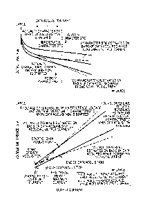
[005 1] FIG. 4 shows graphs showing a reason for acquiring data while
reducing the output current. (A) in FIG. 4 is a graph showing a transition of
an
actual IV characteristic of the fuel cell stack 1 during the start-up of the
fuel
cell system 100, an IV characteristic (dashed-dotted line) estimated on the
basis of data acquired while increasing the output current and an IV
characteristic (broken line) estimated on the basis of data acquired while
reducing the output current. (B) in FIG. 4 is a graph showing voltage
differences among the reference IV characteristic, the actual IV
characteristic
and the estimated IV characteristic according to the output current.
[0052] During the warm-up of the fuel cell stack 1, the IV characteristic
is
gradually recovered toward the reference IV characteristic also while the data
is acquired by varying the output current with the specified variation width
or
larger. Thus, if the actual IV characteristic when data acquisition is started
and the actual IV characteristic when the data acquisition is finished are
compared as shown in (A) of FIG. 4, the IV characteristic when the data
acquisition is finished is a better IV characteristic than the IV
characteristic
when the data acquisition is started.
[0053] Then, if the gradient A and the intercept B of equation (3) are
calculated on the basis of the data (reference voltage and actual output
voltage)
acquired at an arbitrary output current value while increasing the output
current within the data acquisition area as shown by dashed-dotted line in (B)
of FIG. 4, the calculated gradient A becomes smaller than the gradient of the
linear function of the voltage difference AV between the reference voltage and
the voltage on the actual IV characteristic when the data acquisition is
finished.
[0054] Thus, the IV characteristic estimated on the basis of the data
acquired while increasing the output current within the data acquisition area
CA 02909284 2015-10-09
-13-
becomes a better IV characteristic than the actual IV characteristic when the
data acquisition is finished as shown by dashed-dotted line in (A) of FIG. 4.
If
the travel permit is issued on the basis of the better IV characteristic than
the
actual IV characteristic, the output voltage may fall below the minimum
voltage necessary to drive a motor for vehicle travel when the output current
increases due to vehicle travel.
[0055] Contrary to this, if the gradient A and the intercept B of equation
(3)
are calculated on the basis of the data acquired at an arbitrary output
current
value while reducing the output current within the data acquisition area as
shown by broken line in (B) of FIG. 4, the calculated gradient A becomes
larger
than the gradient of the linear function of the voltage difference AV between
the
reference voltage and the voltage on the actual IV characteristic when the
data
acquisition is finished.
[0056] Thus, the IV characteristic estimated on the basis of the data
acquired while reducing the output current within the data acquisition area
becomes a worse IV characteristic than the actual IV characteristic when the
data acquisition is finished as shown by dashed line in (B) of FIG. 4. If the
travel permit is issued on the basis of the worse IV characteristic than the
actual IV characteristic, there is no possibility that the output voltage
falls
below the minimum voltage even if the output current increases due to vehicle
travel.
[0057] Further, in order to ensure the estimation accuracy of an IV
characteristic, the IV characteristic needs to be estimated on the basis of
data
when an output current of a fuel cell is changed with a specified current
width
or larger. Thus, if the output current of the fuel cell is suddenly increased
by
a predetermined current width to accurately estimate the IV characteristic
during warm-up in which power generation becomes unstable due to water or
CA 02909284 2015-10-09
- 14 -
ice in the fuel cell, a voltage drop may occur due to such a sudden current
change.
[0058] On the other hand, if it is attempted to estimate the IV
characteristic
on the basis of the output voltage when the output current of the fuel cell is
gradually increased in order to prevent such a voltage drop, the IV
characteristic desired to be estimated may change during the rise of the
output
current and it may be impossible to ensure estimation accuracy since the IV
characteristic changes from moment to moment during the warm-up of the
fuel cell.
[0059] Contrary to this, if the IV characteristic is estimated on the basis
of
the data acquired while reducing the output current within the data
acquisition area, water and ice in a fuel cell stack are not increased by
power
generation as when the output current is increased. Thus, the occurrence of
a voltage drop due to this can be suppressed.
[0060] Since there is no concern about the occurrence of a voltage drop,
the
output current can be changed at a faster rate than in the case of increasing
the output current. Thus, a change of the IV characteristic while data
necessary for the IV characteristic is acquired can be small, wherefore the
estimation accuracy of the IV characteristic can be ensured.
[0061] Thus, in the present embodiment, the IV characteristic is estimated
on the basis of the data acquired while reducing the output current.
[0062] To estimate the IV characteristic during warm-up in which no travel
permit is issued in this way, the output current needs to be controlled to a
target output current for IV characteristic estimation to reduce the output
current with the specified variation width or larger from the IV estimation
lower limit current to the pre-travel permit maximum current.
[0063] FIG. 5 is a control block diagram for setting the target output
CA 02909284 2015-10-09
-15-
current according to the present embodiment.
[0064] A target auxiliary machine consumption power calculation unit 61
calculates a target value of power to be consumed by each auxiliary machine
such as the cathode compressor 23 (hereinafter, referred to as "target
auxiliary
machine consumption power"). During warm-up in which no travel permit is
issued, the target auxiliary machine consumption power is set at
predetermined warm-up target consumption power. In this embodiment, the
warm-up target consumption power is set at power when the consumption
power of each auxiliary machine is maximized.
[0065] The target auxiliary machine consumption power and target travel
motor supply power are input to a destination target generated power
calculation unit 62. The destination target generated power calculation unit
62 calculates the sum of the target auxiliary machine consumption power and
the target travel motor supply power as destination target generated power.
The target travel motor supply power increases as the accelerator operation
amount increases and is zero regardless of the accelerator operation amount
during warm-up in which no travel permit is issued.
[0066] The destination target generated power and actual generated power
(actual output voltage x actual output current) are input to a basic target
output current calculation unit 63. The basic target output current
calculation unit 63 calculates a target value of the generated power when the
actual generated power is changed toward the destination target generated
power as basic target generated power on the basis of a deviation between the
destination target generated power and the actual generated power. Further,
the basic target output current calculation unit 63 calculates a target value
of
the output current required to make the generated power the basic target
generated power as a basic target output current.
CA 02909284 2015-10-09
-16-
[0067] A battery
charge amount and a battery temperature are input to a
chargeable/ dischargeable power calculation unit 64. The
chargeable/dischargeable power calculation unit 64 calculates power
chargeable into the battery 45 (hereinafter, referred to as "chargeable
power")
and power extractable from the battery 45 (hereinafter, referred to as
"dischargeable power") on the basis of the battery charge amount and the
battery temperature.
[0068] The basic
target generated power, the chargeable power and the
dischargeable power are input to an IV estimation target current calculation
unit 65. The IV estimation target current calculation unit 65 calculates a
target value of the output current when the IV characteristic is estimated
(hereinafter, referred to as an "IV estimation target current) on the basis of
these input values and outputs an ON/OFF signal of an IV estimation
execution flag. When the fuel cell system is started up, the IV estimation
execution flag is set to OFF. The detailed contents of the IV estimation
target
current calculation unit 65 are described later with reference to FIGS. 6 to
9.
[0069] The IV
estimation target current and the basic target output current
are input to a target output current calculation unit 66. The target output
current calculation unit 66 calculates the IV estimation target current as a
target output current if the IV estimation execution flag is ON. On the other
hand, the target output current calculation unit 66 calculates the basic
target
output current as the target output current if the IV estimation execution
flag
is OFF.
[0070] FIG. 6 is a
time chart showing changes of the output current and the
generated power controlled by the control block diagram of FIG. 5.
[0071] In FIG.
6(B), a broken line A represents the basic target generated
power. A broken line B represents power obtained by adding the chargeable
CA 02909284 2015-10-09
-17-
power to the basic target generated power (hereinafter, referred to as "upper
limit generated power"). A broken line C represents power obtained by
subtracting the dischargeable power from the basic target generated power
(hereinafter, referred to as "lower limit generated power").
[0072] Note that a dashed-dotted line D represents the destination target
generated power during warm-up in which no travel permit is issued after the
start-up of the fuel cell system, i.e. the warm-up target consumption power.
A dashed-dotted line E represents power obtained by adding the chargeable
power to the destination target generated power and represents the upper limit
generated power after the auxiliary machine consumption power increases to
the destination target generated power (hereinafter, referred to as 'steady-
state
upper limit generated power). A dashed-dotted line F represents power
obtained by subtracting the dischargeable power from the destination target
generated power and represents the lower limit generated power after the
auxiliary machine consumption power increases to the destination target
generated power (hereinafter, referred to as "steady-state lower limit
generated
power).
[0073] In FIG. 6(A), a broken line A represents the basic target output
current. A broken line B represents an output current Ici required to make
the generated power the upper limit generated power (hereinafter, referred to
as "upper limit output current"). A broken line C represents an output
current 1,2 required to make the generated power the lower limit generated
power (hereinafter, referred to as "lower limit output current"). The output
current can be varied from the lower limit output current 1,2 to the upper
limit
output current I,' during warm-up in which no travel permit is issued.
[0074] Note that a dashed-dotted line D represents an output current
required to make the generated power the steady-state upper limit generated
CA 02909284 2015-10-09
-18-
power, i.e. the pre-travel permit maximum current. A dashed-dotted line E
represents an output current la required to make the generated power the
steady-state lower limit generated power (hereinafter, referred to as
"steady-state lower limit output current). A dashed-dotted line F represents
an IV estimation lower limit current Ic3.
[0075] When the fuel cell system 100 is started up, the warm-up target
consumption power is set as the destination target output power and a target
value for making the generated power the warm-up target consumption power
is set as the basic target generated power as shown in FIG. 6(B).
[0076] As a result, the basic target output current is set as the target
output current and the output current is controlled to the basic target output
current as shown in FIG. 6(A) since the IV estimation execution flag is set at
OFF when the fuel cell system 100 is started up.
[00771 At time to, the output current of the fuel cell stack 1 reaches the
steady-state lower limit current Ia. When a difference between the upper
limit output current Li and the steady-state lower limit current 'a becomes
equal to or larger than a predetermined current variation width Alt necessary
to ensure predetermined accuracy when the IV characteristic is estimated at
time ti, the IV estimation execution flag is set to ON. Then, the upper limit
output current It2 at time t 1 (hereinafter, referred to as a "load increasing
target current") is set as the IV estimation target current.
[0078] As a result, the IV estimation target current is set as the target
output current and the output current is controlled to reach the load
increasing target current It2 as shown in FIG. 6(A).
[0079] When the output current reaches the load increasing target current
It2 at time t2, the output current is maintained at the load increasing target
current It2 until the elapse of a predetermined time from that point of time.
CA 02909284 2015-10-09
-19-
[0080] When the
elapsed time from time t2 reaches the predetermined time
at time t3, the steady-state lower-limit current Iti is set as the IV
estimation
target current and the output current is changed to the steady-state
lower-limit current hi at a predetermined change rate. While the output
current is changed to the steady-state lower-limit current Iti at the
predetei _________________________________________________________ mined
change rate, a plurality of pieces of data on the reference
voltages and the actual output voltages corresponding to arbitrary output
current values are acquired.
[0081] When the
output current decreases to the steady-state lower limit
current Iti at time t4, the IV characteristic is estimated on the basis of
acquired
parameters. Then, the IV estimation execution flag is set to OFF and the
output current is controlled to reach the basic target output current again.
[0082] FIG. 7 is a
flow chart showing an IV characteristic estimation control
according to the present embodiment.
[0083] In Step Si,
the controller 5 calculates the steady-state lower limit
current Li. Specifically, the steady-state lower limit generated power is
calculated by subtracting the dischargeable power from the destination target
generated power during warm-up in which no travel permit is issued (warm-up
target consumption power). Then, the output current required to make the
generated power the steady-state lower limit generated power is calculated as
the steady-state lower limit current Ia.
[0084] In Step S2,
the controller 5 determines whether or not the difference
between the upper limit output current hi and the steady-state lower limit
current hi has become equal to or larger than the current variation width It
necessary to ensure predetermined accuracy when the IV characteristic is
estimated. The controller 5 repeats this processing until the difference
between the upper limit output current Id and the steady-state lower limit
CA 02909284 2015-10-09
-20 -
current Iti becomes equal to or larger than the current variation width Alt
and
performs a processing of Step S3 if the difference between the upper limit
output current Li and the steady-state lower limit current Iti becomes equal
to
or larger than the current variation width Alt.
[0085] In Step S3, the controller 5 performs a transient-state IV
characteristic estimation process. The transient-state IV characteristic
estimation process is the first IV characteristic estimation process performed
after the fuel cell system 100 is started up and an IV characteristic
estimation
process performed in a transient state before the auxiliary machine
consumption power reaches the warm-up target consumption power. The
details of the transient-state IV characteristic estimation process are
described
later with reference to FIG. 8.
[00861 In Step S4, the controller 5 determines whether or not the IV
characteristic has been estimated in the transient-state IV characteristic
estimation process. The controller 5 performs a processing of Step S5 if the
IV
characteristic has been estimated while performing a processing of Step S8
unless otherwise.
[00871 In Step S5, the controller 5 determines on the basis of the IV
characteristic estimated in the transient-state IV characteristic estimation
process whether or not the output voltage when the travel permit current was
extracted from the fuel cell stack 1 is below the minimum voltage. The
controller 5 performs a processing of Step S6 unless the output voltage when
the travel permit current was extracted from the fuel cell stack 1 is below
the
minimum voltage. On the other hand, the controller 5 performs a processing
of Step S7 if the output voltage when the travel permit current was extracted
from the fuel cell stack 1 is below the minimum voltage.
[0088] In Step S6, the controller 5 issues the vehicle travel permit.
CA 02909284 2015-10-09
-21-
[0089] In Step S7,
the controller 5 sets an interval period Tint until a
steady-state IV characteristic estimation process to be described later is
performed after the transient-state IV characteristic estimation process is
performed to zero.
[0090] In Step S8,
the controller 5 performs the steady-state IV
characteristic estimation process. The steady-
state IV characteristic
estimation process is the second or subsequent IV characteristic estimation
process performed after the transient-state IV characteristic estimation
process is performed and basically an IV characteristic estimation process
performed in a steady state after the auxiliary machine consumption power
reaches the warm-up target consumption power. The details of the
steady-state IV characteristic estimation process are described later with
reference to FIG. 9.
[0091] In Step S9,
the controller 5 determines on the basis of the IV
characteristic estimated in the steady-state IV characteristic estimation
process whether or not the output voltage when the travel permit current was
extracted from the fuel cell stack 1 is below the minimum voltage. The
controller 5 performs the processing of Step S6 unless the output voltage when
the travel permit current was extracted from the fuel cell stack 1 is below
the
minimum voltage. On the other hand, the controller 5 performs a processing
of Step S10 if the output voltage when the travel permit current was extracted
from the fuel cell stack 1 is below the minimum voltage.
[0092] In Step
S10, the controller 5 sets the interval period tint to a variable
value tin'. The variable value tmi is set to be shorter as the IV
characteristic
estimated in the steady-state IV characteristic estimation process
approximates to the reference IV characteristic, i.e. as the IV characteristic
is
recovered.
CA 02909284 2015-10-09
-22-
[0093] FIG. 8 is a flow chart showing the transient-state IV characteristic
estimation process.
[0094] In Step S31, the controller 5 sets the IV estimation execution flag
to
ON.
[0095] In Step S32, the controller 5 sets the smaller one of the upper
limit
output current It2 when the difference between the upper limit output current
Ici and the steady-state lower limit current Iti becomes equal to or larger
than
the predetermined current variation width Alt (hereinafter, referred to as the
"load increasing target current") and the present upper limit output current
Lc'
as the IV estimation target current. The load increasing target current It2 is
basically set as the IV estimation target current in this Step. The smaller
one
of the load increasing target current It2 and the present upper limit output
current Ici is set as the IV estimation target current for the following
reason.
Specifically, if the load increasing target current It2 irregularly becomes
larger
than the present upper limit output current Li when the output current is
maintained at the IV estimation target current in Step S33 to be described
later,
a charge current becomes excessive and the battery 45 is deteriorated. To
prevent this, the above setting is made.
[0096] In Step S33, the controller 5 determines whether or not a
predetermined time has elapsed after the output current reached the IV
estimation target current set in Step S32. The controller 5 performs a
processing of Step S34 unless the predetermined time has elapsed after the
output current reached the IV estimation target current while preforming a
processing Step S37 if the predetermined time has elapsed.
[0097] In Step S34, the controller 5 performs a voltage drop determination.
Specifically, whether or not the output voltage has dropped by a predetermined
voltage to be below a voltage drop determination value is determined when the
CA 02909284 2015-10-09
-23-
output current is maintained at the IV estimation target current. The
controller 5 performs a processing of Step S35 to stop the transient-state IV
characteristic estimation process if the output voltage is below the
predetermined voltage drop determination value. On the other hand, a return
is made to the processing of Step S32 unless the output voltage is below the
predetermined voltage drop determination value.
[0098] In Step S35, the controller 5 stops the transient-state IV
characteristic estimation process by setting the IV estimation execution flag
to
OFF. Then, the basic target output current is set as the target output current
and the output current is controlled to the basic target output current.
[0099] In Step S36, the controller 5 sets the interval period tint to a
predetermined fixed value tm2. The fixed value tm2 is a value larger than the
variable value tmi.
[0100] In Step S37, the controller 5 determines whether or not a value
obtained by subtracting the current variation width Alt from the present
output current Jr (= IV estimation target current set in Step S32) is not
smaller
than the lower limit output current Ic2 and the IV estimation lower limit
current Ic3. The controller 5 performs a processing of Step S38 if the value
obtained by subtracting the current variation width Alt from the present
output current Ir is not smaller than the lower limit output current Ic2 and
the
IV estimation lower limit current Ic3. On the other hand, a processing of Step
S43 is performed to stop the transient-state IV characteristic estimation
process if the value obtained by subtracting the current variation width Alt
from the present output current Ir is smaller than the lower limit output
current Ic2 and the IV estimation lower limit current Ic3.
[0101] In Step S38, the controller 5 sets the larger one of the value
obtained
by subtracting the current variation width Alt from the present output current
CA 02909284 2015-10-09
-24 -
Ir and the lower limit output current Ic2 as the IV estimation target current
and
reduces the output current toward the IV estimation target current at a
predetermined change rate.
[0102] In Step S39, the controller 5 acquires data on the reference
voltages
and the actual output voltages while the output current is reduced.
[0103] In Step S40, the controller 5 determines whether or not the output
current has been reduced to the IV estimation target current set in Step S38.
The controller 5 performs a processing of Step S41 if the output current has
been reduced to the IV estimation target current while returning to the
processing of Step S39 to acquire the above three parameters unless
otherwise.
[0104] In Step S41, the controller 5 finishes the acquisition of the data
on
the reference voltages and the actual output voltages and estimates the IV
characteristic on the basis of the acquired data.
[0105] In Step S42, the controller 5 sets the IV estimation execution flag
to
OFF, sets the basic target output current as the target output current and
controls the output current to the basic target output current.
[0106] In Step S43, the controller 5 stops the transient-state IV
characteristic estimation process by setting the IV estimation execution flag
to
OFF. Then, the basic target output current is set as the target output current
and the output current is controlled to the basic target output current.
[0107] In Step S44, the controller 5 sets the interval period tint to zero.
[0108] FIG. 9 is a flow chart showing the steady-state IV characteristic
estimation process.
[0109] In Step S81, the controller 5 determines whether or not an elapsed
time after the interval period tint was set has become longer than the set
interval period tint. The controller 5 repeats this processing until the
interval
CA 02909284 2015-10-09
-25 -
period tint elapses and performs a processing of Step S82 upon the elapse of
the
interval period tint.
[0110]In Step S82, the controller 5 determines whether or not a difference
between the upper limit output current Ici and the larger one of the lower
limit
output current 1,2 and the IV estimation lower limit current 1,3 is not
smaller
than the current variation width Alt. The controller 5 performs a processing
of
Step S83 if the difference between the upper limit output current 1,1 and the
larger one of the lower limit output current 1,2 and the IV estimation lower
limit
current Ic3 is not smaller than the current variation width Alt while
continuing
this processing until the difference becomes equal to or larger than the
current
variation width Alt unless otherwise.
[0111] In Step S83, the controller 5 sets the IV estimation execution flag
to
ON.
[0112] In Step S84, the controller 5 sets the smaller one of the upper
limit
output current Id when the difference between the upper limit output current
Id i and the larger one of the lower limit output current 1,2 and the IV
estimation
lower limit current 1,3 becomes equal to or larger than the current variation
width Alt and the present upper limit output current I,' as a load increasing
IV
estimation target current.
[0113] In Step S85, the controller 5 determines whether or not a
predetermined time has elapsed after the output current reached the load
increasing IV estimation target current set in Step S84. The controller 5
performs a processing of Step S86 unless the predetermined time has elapsed
after the output current reached the load increasing IV estimation target
current while performing a processing of Step S89 if the predetermined time
has elapsed.
[0114] In Step S86, the controller 5 performs a voltage drop determination.
CA 02909284 2015-10-09
-26-
Specifically, whether or not the output voltage has dropped below a
predetermined voltage drop determination value when the output current is
maintained at the load increasing IV estimation target current is determined.
The controller 5 performs a processing of Step S87 to perform the steady-state
IV characteristic estimation process again after the elapse of a predetermined
interval period if the output voltage has dropped below the predetermined
voltage drop determination value. On the other hand, a return is made to
Step S84 if the output voltage is not smaller than the predetermined voltage
drop determination value.
[0115] In Step S87, the controller 5 sets the IV estimation execution flag
to
OFF, sets the basic target output current as the target output current and
controls the output current to the basic target output current.
[0116] In Step S88, the controller 5 sets the interval period tint to the
predetermined fixed value tm2 and, thereafter, a return is made to Step S81 to
start the IV characteristic estimation process again after the elapse of the
set
interval period.
[0117] In Step S89, the controller 5 determines whether or not a value
obtained by subtracting the current variation width AI t from the present
output current Jr is not smaller than the lower limit output current 1,2 and
the
IV estimation lower limit current Ic3. The controller 5 performs a processing
of
Step S90 if the value obtained by subtracting the current variation width Alt
from the present output current Jr is not smaller than the lower limit output
current la and the IV estimation lower limit current Ir3. On the other hand, a
processing of Step S95 is performed if the value obtained by subtracting the
current variation width Alt from the present output current Jr is smaller than
the lower limit output current la and the IV estimation lower limit current
Ir3.
[0118] In Step S90, the controller 5 sets the larger one of the value
obtained
CA 02909284 2015-10-09
-27-
by subtracting the current variation width Aft from the present output current
Ir and the lower limit output current Ic2 as a load decreasing IV estimation
target current and reduces the output current toward the load decreasing IV
estimation target current at a predetermined change rate.
[0119] In Step S91, the controller 5 acquires data on the reference
voltages
and the actual output voltages while reducing the output current.
[0120] In Step S92, the controller 5 determines whether or not the output
current has been reduced to the load decreasing IV estimation target current
set in Step S89. The controller 5 performs a processing of Step S93 if the
output current has been reduced to the load decreasing IV estimation target
current while returning to the processing of Step S91 to acquire data unless
otherwise.
[0121] In Step S93, the controller 5 finishes the acquisition of the data
on
the reference voltages and the actual output voltages and estimates the IV
characteristic.
[0122] In Step S94, the controller 5 sets the IV estimation execution flag
to
OFF, sets the basic target output current as the target output current and
controls the output current to the basic target output current.
[0123] In Step S95, the controller 5 sets the IV estimation execution flag
to
OFF. Then, the basic target output current is set as the target output
current,
the output current is controlled to the basic target output current and a
return
is made to Step S82 to start the IV characteristic estimation process again.
[0124] As described above, according to the present embodiment, the IV
characteristic of the fuel cell stack 1 is estimated on the basis of the data
acquired at an arbitrary output current value (reference voltage and the
actual
output voltage) while the output current of the fuel cell stack 1 is reduced.
[0125] Thus, water and ice are not suddenly increased unlike in the case of
CA 02909284 2015-10-09
-28 -
estimating the IV characteristic by increasing the output current of the fuel
cell
stack 1, wherefore the occurrence of a voltage drop caused by this can be
suppressed. Further, since there is no concern about the occurrence of a
voltage drop, the current can be quickly reduced. Therefore, a change of the
IV characteristic during the acquisition of the data necessary for IV
estimation
can be small and the estimation accuracy of the IV characteristic can be
ensured.
[0126] Further, the IV characteristic estimated on the basis of the data
acquired while reducing the output current of the fuel cell stack 1 becomes an
IV characteristic worse than the actual IV characteristic when the data
acquisition is finished. By issuing the vehicle travel permit on the basis of
the
IV characteristic worse than the actual IV characteristic, a drop of the
output
voltage below the minimum voltage can be suppressed even if the output
current is increased by vehicle travel.
[0127] Further, according to the present embodiment, the fuel cell stack 1
is caused to generate power to promote the warm-up in a state where self-heat
generation is actively used by basically setting the target value of the
generated
power at the warm-up target consumption power and maximizing the
consumption power of each auxiliary machine such as the cathode compressor
23 during the warm-up of the fuel cell stack 1. In estimating the IV
characteristic, the generated power is made larger than the warm-up target
consumption power by supplying a part of the generated power of the fuel cell
stack 1 to the battery 45, the output current is reduced after the output
current is increased and the IV characteristic of the fuel cell stack 1 is
estimated on the basis of the data acquired when the output current is
reduced.
[0128] To promote the warm-up of the fuel cell stack 1, it is desirable to
CA 02909284 2015-10-09
-29 -
cause the fuel cell stack 1 to generate power in a state where the consumption
power of each auxiliary machine is maximized and the self-heat generation is
actively used. However, if the consumption power of each auxiliary machine
(power supplied to each auxiliary machine) is reduced to reduce the output
current in order to estimate the IV characteristic, warm-up performance is
deteriorated since the amount of self-heat generation is reduced.
[0129] Accordingly, by supplying the generated power of the fuel cell stack
1 to the battery 45 with the consumption power of each auxiliary machine
maximized and reducing the output current after the output current is
increased as in the present embodiment, it is possible to estimate the IV
characteristic while suppressing the deterioration of warm-up performance.
[0130] Further, according to the present embodiment, the IV characteristic
is estimated in the transient state before the auxiliary machine consumption
power reaches the warm-up target consumption power after the start-up of the
fuel cell stack 100.
[0131] In this way, the IV characteristic can be estimated earlier as
compared with the case where the IV characteristic is estimated in the steady
state after the auxiliary machine consumption power reaches the warm-up
target consumption power.
[0132] Further, since the lower limit output current also increases with an
increase in the auxiliary machine consumption power while the output current
is reduced when it is attempted to estimate the IV characteristic by acquiring
predetermined data while reducing the output current in such a transient
state, the accuracy of the IV characteristic may be reduced without being able
to ensure the predetermined current variation width Alt.
[0133] Contrary to this, in the present embodiment, the steady-state lower
limit current Iii, i.e. the minimum value of the output current extractable in
CA 02909284 2015-10-09
-30-
the steady state after the auxiliary machine consumption power reaches the
warm-up target consumption power is calculated, and the IV estimation was
carried out on the basis of this steady-state lower limit current Iti when the
predetermined current variation width AIL can be ensured. The steady-state
lower limit current hi can be also called as a maximum value of the lower
limit
output current in the transient state. Thus, by carrying out the IV estimation
on the basis of the steady-state lower limit current In when the predetermined
current variation width Alt can be ensured, the output current can be reliably
reduced by the current variation width Alt, wherefore the accuracy of the IV
characteristic can be ensured.
[0134] As just described, according to the present embodiment, the
accuracy of the IV characteristic can be ensured also in the transient state.
Thus, the vehicle travel permit can be quickly issued such as when the IV
characteristic is suddenly recovered during warm-up.
[0135] Further, according to the present embodiment, the upper limit
output current Li and the steady-state lower limit current Iti can be
calculated
according to a state of the battery such as the battery charge amount,
wherefore the over-charge and over-discharge of the battery 45 can be
prevented and the deterioration of the battery 45 can be prevented.
[0136] Although the embodiment of the present invention has been
described above, the above embodiment is merely an illustration of one
application example of the present invention and not of the nature to limit
the
technical scope of the present invention to the specific configuration of the
above embodiment.
[0137] For example, in the above embodiment, the IV estimation is started
by controlling the output current to the load increasing target current It2 in
order to reliably ensure the current variation width Alt when the difference
CA 02909284 2015-10-09
-3 1 -
between the upper limit output current Ici and the steady-state lower limit
current Iti becomes equal to or larger than the predetermined current
variation
width AIt. However, the IV estimation may be started by increasing the output
current as long as it is already determined that the output current has
reached
the steady-state lower limit current Iti. Effects similar to those of the
above
embodiment can be obtained also by this.