Note: Descriptions are shown in the official language in which they were submitted.
CA 02909346 2015-10-09
WO 2014/167301 PCT/GB2014/051073
1
Inflatable Flood Defence Structural Unit and Arrangement
This invention present invention relates to an inflatable flood defence
structural unit and arrangement.
Conventional flood defences are produced from rigid materials such as
concrete or particulate materials such as soil, sand and stone. Such defences
are permanent in nature and take up a large volume. They are also time
consuming to build so they are either permanent structures erected on site, or
if
prefabricated, cannot be deployed quickly in an emergency due to their size
and
weight. Also some structures are susceptible to erosion by flowing flood
water.
Inflatable defences have been proposed by others to protect buildings
from flooding, for example GB2411423A. However, these are not particularly
strong and require a permanent fixing around the perimeter of the building to
support the defence. These known inflatable defences are held to the ground or
the base of the building because they would otherwise float away, and thus
they
require a high strength fixing at their base.
We have now devised a defence or water dam which is inflatable and
which requires minimal site preparation. Such a defence can then be deployed
quickly, where needed, and removed after use, so need not be permanently
located.
According to one aspect of the invention, there is provided an inflatable
flood defence structural unit comprising:
at least one inflatable chamber comprising a front wall and a rear wall
which extend in a substantially parallel orientation, at least one of the
front and
CA 02909346 2015-10-09
WO 2014/167301 PCT/GB2014/051073
2
rear walls providing a water barrier, and a first and second end wall which
couple the front and rear walls together at a respective first and second end
of
the front and rear walls,
a first inflatable buttress which is rigidly bonded at a proximal end thereof
to the rear wall of the chamber, proximate the first end of the chamber, and
which extends in a direction which is away from the chamber,
a second inflatable buttress which is rigidly bonded at a proximal end
thereof to the rear wall of the chamber, proximate the second end of the
chamber, and which extends in a direction which is away from the chamber,
and a fastening arrangement disposed upon at least one of the first or
second buttress for fastening the first and second buttress to a second and
first
buttress respectively, of a further structural unit.
In use, the front wall of the unit is arranged to face the flood water or
impending flood water such that the buttresses provide a support to the
chamber
against the force of the flood water, for example. The bonding of the
buttresses
to the chamber provides a water seal therebetween and thus prevents any water
passing between the buttress and the chamber, whereas the fastening
arrangement enables the respective buttresses to be held together tightly to
provide a substantially water seal along an interface therebetween.
Preferably, the front and rear walls of the chamber are interconnected by
a multiplicity of interconnecting members which extend across the chamber. In
this way an inflatable defence or water dam can be provided which is rigid
when
inflated by virtue of the interconnecting members. This rigidity means that
the
defence can, if necessary, be self-supporting and can be higher than other
CA 02909346 2015-10-09
WO 2014/167301 PCT/GB2014/051073
3
known inflatable structures. The structure is preferably water fillable
without
bulging because the interconnecting members hold the front and rear walls in
place. This results in a heavy structure which will not lift in the flood
water. As a
result, it is not essential that the structure is fixed or sealed to the
ground.
The first and second buttresses comprise side walls which couple the
proximal end of the respective buttress to a distal end of the respective
buttress.
The side walls of each buttress separately comprise an inner wall which faces
inwardly of the unit, substantially toward each other, and an outer wall which
face outwardly of the unit, substantially away from each other.
In an embodiment, the outer side wall of the first buttress is substantially
aligned with the first end of the chamber and the outer side wall of the
second
buttress is substantially aligned with the second end of the chamber. In this
manner the outer side walls of the first and second buttress extends in a
plane
comprising the first and second end of the chamber, respectively.
In an alternative embodiment, the outer side wall of the first buttress
extends beyond the first end of the chamber, such that the proximal end of the
first buttress overhangs the first end of the chamber, and the outer side wall
of
the second buttress is spaced from the second end of the chamber. Preferably,
the spacing of the outer side wall of the second buttress from the second end
of
the chamber substantially corresponds with the extent to which the outer side
wall of the first buttress extends beyond the first end of the chamber.
The unit thus facilitates the joining together of a plurality of units whereby
the first end wall of the chamber of one unit may be abutted to the second end
wall of a chamber of a neighbouring unit, such that the buttresses may be
CA 02909346 2015-10-09
WO 2014/167301 PCT/GB2014/051073
4
fastened together using the fastening arrangement to create a watertight seal
along the interface therebetween. The alternative embodiment provides for an
improved sealing however, since the buttress at the first end of the one unit
extends over the rear wall of the chamber of a further unit at the second end
thereof. The relative positioning of the first and second buttresses enables
the
portion of the first buttress to extend over the chamber wall of the further
unit, to
offset the interface between adjoining buttresses and the interface between
the
ends walls of the chamber. Accordingly, in addition to providing a labyrinth
type
seal between the units, the buttress at the first end of the structural unit
provides
additional support to neighbouring chambers.
Conveniently, the unit comprises a skirt located at a lower region of the
chamber, in use extending toward the flood water or impending flood water. The
skirt may be arranged to lie on the ground adjacent the chamber and may be
rigidly bonded to the chamber to provide a substantially watertight seal
between
the chamber and the skirt.
The unit preferably further comprises an apron which in use, extends
along the front wall of the chamber beyond an end wall of the chamber to
extend
over the interface between neighbouring chambers. The apron forms a
watertight seal with the front walls of the neighbouring chambers under the
force
of the flood water to further enhance the sealing between the neighbouring
units
and thus the integrity of the resulting flood defence.
In one embodiment one of the front and rear walls, or both front and rear
walls are substantially impermeable to water.
CA 02909346 2015-10-09
WO 2014/167301 PCT/GB2014/051073
In yet a further embodiment, the first and second buttresses extend away
from the chamber in a direction which is substantially perpendicular to the
rear
wall of the chamber. It is envisaged that this arrangement will facilitate the
creation of a substantially linear flood defence arrangement.
5 In
yet a further alternative embodiment at least one of the first or second
buttresses extends in a direction which is substantially acutely orientated
with
respect to the rear wall of the chamber. It is envisaged that this arrangement
will
facilitate the creation of a corner within a flood defence arrangement,
whereby
the arrangement is arranged to prevent flood water entering a defined area. In
this respect, at least one of the buttresses extend inwardly of the area, at
an
inner side of the corner. It is also envisaged however, that at least one of
the first
and second buttresses may extend at an obtuse angle with respect to the rear
wall of the chamber in situations whereby the arrangement is arranged to
contain flood water, such as when creating a reservoir. In this respect, the
buttress is arranged at an outer side of the reservoir, at an outer side of
the
corner.
Preferably, the fastening arrangement comprises at least one strap which
is rigidly coupled to at least one of the first or second buttress and a
tensioning
arrangement, such as a ratchet, which is rigidly coupled to the second or
first
buttress respectively, for controllably pulling the strap to secure
neighbouring
buttresses together.
Suitably, the or each chamber is formed from so-called drop-stitch
material. Said drop stitch material may have two polymer coated fabric sheets
separated by a multiplicity of fibres or threads, each being attached to the
inner
CA 02909346 2015-10-09
WO 2014/167301 PCT/GB2014/051073
6
sides of the sheets. The drop stitch material thus has a forest of fibres
connecting the two sheets. When inflated with a fluid, the chamber formed from
drop stitch material produces a rigid structure.
Preferably the flood defence unit further comprises an inflatable spacer
for spacing the chamber of the unit from an adjacent wall in use, for example.
Such spacer may comprise a similar structure and be formed of a similar
material to the chamber.
The unit may further comprise an inflatable wedge for levelling the
chamber upon a slope. The wedge may comprise a similar structure and be
formed of a similar material to the chamber.
According to a second aspect of the invention there is provided an
inflatable flood defence arrangement comprising a plurality of inflatable
flood
defence structural units of the first aspect.
The invention extends to any novel feature described herein, or any novel
combination of features described.
It will be understood that the invention can be put into effect in many ways
and by way of illustration only, embodiments of the invention are described
below, with reference to the drawings, wherein:
Figure la is a plan view of a flood defence structural unit according to a
first embodiment of the present invention;
Figure lb is a side view of the structural unit illustrated in figure 1;
Figure lc is a plan view of a portion of a linear flood defence arrangement
according to an embodiment of the present invention;
CA 02909346 2015-10-09
WO 2014/167301 PCT/GB2014/051073
7
Figure 2a is a plan view of a flood defence structural unit according to a
second embodiment of the present invention;
Figure 2b is a perspective view from the rear of an interface between two
structural units of the flood defence arrangement illustrated in figure 2a;
Figure 2c is a plan view of a flood defence arrangement according to an
embodiment of the present invention.
Figure 3a is a plan view of a flood defence structural unit according to a
third embodiment of the present invention;
Figure 3b is a plan view of a flood defence arrangement formed using a
plurality of flood defence units illustrated in figure 3a;
Figure 3c is a plan view of a flood defence structural unit according to a
variation of the structural unit of the third embodiment of the present
invention;
Figure 3d is a plan view of a flood defence arrangement formed using a
plurality of flood defence units illustrated in figure 3c;
Figure 4 is front view of spacer disposed between a wall and the
structural unit illustrated in figure 1; and,
Figure 5 is a schematic illustration of a wedge disposed at the underside
of the structural unit illustrated in figure 1, located upon a slope.
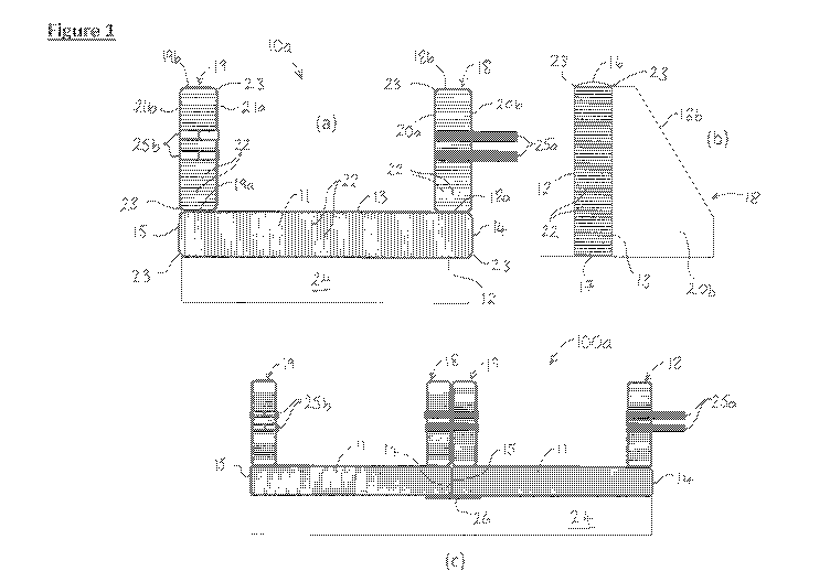
Referring to Figure la of the drawings, there is illustrated a plan view of
an inflatable flood defence structural unit 10a according to a first
embodiment of
the present invention, for providing a barrier to flood water and the like.
The unit
10a comprises an inflatable main chamber 11 comprising a substantially planar,
front 12 and rear wall 13, which extend in a substantially parallel
orientation.
Opposite longitudinal ends of the chamber 11, namely a first and second end,
of
CA 02909346 2015-10-09
WO 2014/167301 PCT/GB2014/051073
8
the chamber comprise a first 14 and second end wall 15 which couple the front
and rear walls 12, 13 together to close the first and second end of the
chamber
11, whereas the upper and lower regions of the chamber are closed by
respective upper 16 and lower end walls 17.
The unit 10a further comprises a first 18 and second buttress 19, which
are coupled at a proximal end wall 18a, 19a thereof to the rear wall 13 of the
chamber 11. The buttresses 18, 19 comprise side walls 20, 21 which extend
from the proximal end wall 18a, 19a thereof to a respective distal end wall
18b,
19b thereof in a direction which is substantially perpendicular to the rear
wall 13
of the chamber 11. The proximal end wall 18a, 19a of each buttress 18, 19
comprises a height which substantially corresponds with a height of the
chamber
11 and the side walls 20, 21 of each buttress 18, 19 reduce in height in
progressing from the proximal end wall 18a, 19a to the distal end wall 18b,
19b,
such that the distal end wall 18b, 19b comprises a sloping wall, as
illustrated in
figure lb of the drawings.
The buttresses 18, 19 separately comprise a respective inner side wall
20a, 21a which faces inwardly of the unit 10a, substantially toward each
other,
and a respective outer side wall 20b, 21b which face outwardly of the unit
10a,
substantially away from each other. The buttresses 18, 19 associated with the
unit 10a of the first embodiment are positioned upon the rear wall 13 of the
chamber 11, such that the outer side walls 20b, 21b of the first and second
buttress 18, 19 extend in substantially the same plane as the first and second
end walls 14, 15 of the chamber 11, respectively.
CA 02909346 2015-10-09
WO 2014/167301 PCT/GB2014/051073
9
The walls of the chamber 11 and each buttress 18, 19 are formed of a
woven fibre reinforced polymer sheet material. The front and rear walls 12, 13
of
the chamber and opposing side walls 20a, 20b, 21a, 21b of each buttress 18, 19
are separately interconnected by a multiplicity of interconnecting polymer
fibres
or threads 22 which extend across the chamber 11 and each buttress 18, 19,
respectively. The material described in this paragraph is known as drop-stitch
material. The drop stitch material comprises approximately ten threads per
square centimetre, which weave through the interior of the opposing walls, and
which forms the woven fibre. The outer surface of the walls of the chamber 11
and buttresses 18, 19 are coated with pvc, in this instance, although other
waterproof flexible coatings such as rubber or urethane can be used. The edges
of the drop stitch material, for example edges 23 are glued and or heat sealed
to
provided a substantially airtight unit 10a.
The overall structure of the unit 10a can be formed into a substantially air
and/or watertight compartment, which when inflated provides a rigid structure
with inherent mechanical strength to resist bending, tension, and compression.
In particular, the unit 10a can be water filled and yet still support itself.
The unit 10a further comprises a skirt 24 formed of a waterproof material,
which extends from a position proximate a lower region of the chamber 11
forwardly of the chamber 11 away from the front wall 12, and is arranged to
extend under the flood water to further minimise any flood water passing
underneath the chamber 11.
A fastening arrangement 25 is also provided for fastening the unit 10a to
neighbouring units 10a to create a flood defence arrangement or reservoir, for
CA 02909346 2015-10-09
WO 2014/167301 PCT/GB2014/051073
example. In the embodiment illustrated in figure la, the fastening arrangement
25 comprises a pair of straps 25a which are rigidly coupled at one end
thereof,
to the first buttress 18 and a tensioning arrangement such as a pair of
ratchets
25b, rigidly coupled to the second buttress 19 for separately receiving a
strap
5 25a coupled to the first buttress 18 of a further unit 10a.
Accordingly, upon positioning a unit 10a of the first embodiment adjacent
a further unit 10a, the free end of the straps 25a coupled to the first
buttress 18
of one unit 10a can be introduced into the corresponding ratchet 25b disposed
on the adjacent second buttress 19 of the further unit 10a and operated to
10 tension the straps 25a and urge the outer side wall 20b of the first
buttress 18
into contact with the outer side wall 21b of the second buttress 19 of the
further
unit 10a, to create a linear flood defence arrangement 100a according to an
embodiment of the present invention, as illustrated in figure 1c of the
drawings.
Upon further tensioning the straps 25a, a water tight seal can develop between
the outer side walls 20b, 21b of the adjoining buttress 18, 19 and between the
first and second end walls 14, 15 of the adjoining chambers 11. Once coupled
together, an apron 26 or similar formed of a water proof material may be
suitably
positioned upon the front wall 12 of neighbouring chambers 11 to extend across
the interface. In this respect it is envisaged that the apron 26 may be
secured in
place using a VELCRO (RTM) type fastener (not shown), for example.
Referring to figure 2a of the drawings, there is illustrated a flood defence
structural unit 10b according to a second embodiment of the present invention.
The unit 10b of the second embodiment is substantially the same as the unit
10a
CA 02909346 2015-10-09
WO 2014/167301 PCT/GB2014/051073
11
of the first embodiment and as such like features have been referenced using
the same reference numerals.
The unit 10b of the second embodiment however, differs from that of the
first 10a since the buttresses 18, 19 are positioned at a different location
upon
the rear wall 13 of the chamber 11 compared with the first embodiment. In
particular, the first buttress 18 is coupled to the rear wall 13 of the
chamber 11
such that the outer side wall 20b of the first buttress 18 extends beyond the
first
end wall 14 of the chamber 11. The first buttress 18 thus partially overhangs
the
first end wall 14 of the chamber 11. Conversely, the second buttress 19 is
coupled to the rear wall 13 of the chamber 11 but is spaced from the second
end
wall 15 of the chamber 11 by a distance which corresponds to the extent to
which the outer wall 20b of the first buttress 18 extends beyond the first end
wall
14 of the chamber 11, as illustrated in figure 2b of the drawings.
Accordingly, when neighbouring units 10b of the second embodiment are
placed in a side-by-side relation as illustrated in figure 2c of the drawings,
and
fastened together, the first buttress 18 of one unit 10b will partially extend
onto
the rear wall 13 of the further unit 10b. The interface between adjoining
buttresses 18, 19 will thus be offset with respect to the interface between
the
end walls 14, 15 of the adjoining chambers 11. This stepped interface creates
a
labyrinth type seal between adjacent units 10b thereby providing a flood
defence
arrangement 100b according to a second embodiment, which comprises an
improved sealing between adjacent units 10b compared with the first
embodiment of the flood defence arrangement 100a, while the first buttress 18
provides support to both chambers 11 at the interface therebetween.
CA 02909346 2015-10-09
WO 2014/167301 PCT/GB2014/051073
12
Referring to figure 3a of the drawings there is illustrated a flood defence
structural unit 10c according to a third embodiment of the present invention.
The
unit 10c of the third embodiment is substantially the same as the unit 10a of
the
first embodiment and as such like features have been referenced using the
same reference numerals.
The unit 10c of the third embodiment however, differs from that of the first
embodiment, since the first and second buttress 18, 19 extend away from the
rear wall 13 of the chamber 11 at an acute angle thereto. This angle may
comprise a 45 angle such that upon suitably positioning neighbouring units
10c,
adjoining chambers 11 extend in substantially perpendicular directions. The
adjoining buttresses 18, 19 may then be fastened together to create a flood
defence arrangement 100c according to a third embodiment, which follows a
substantially square path, as illustrated in figure 3b of the drawings, to
extend
around the periphery of a property (not shown) for example, to protect against
impending flood water. The skilled reader will recognise however, that
alternative angles may be used, such as a 60 angle to facilitate the creation
of a
defence arrangement which follows a hexagonal path.
In this embodiment, it is envisaged that the first and second end walls 14,
15 of the chamber 11 of the unit 10c may be similarly angularly orientated to
extend in the same plane as the outer walls 20b, 21b of the first and second
buttress 18, 19, respectively, to facilitate the sealing along an interface
therebetween.
The acute angular orientation of the buttresses 18, 19 of the unit 10c of
the third embodiment provide support along an inner side of the respective
CA 02909346 2015-10-09
WO 2014/167301 PCT/GB2014/051073
13
corner sections of the flood defence arrangement 100c when it is desired to
keep flood water out of a protected region. In a variation of the flood
defence unit
10c of third embodiment, there is a provided a flood defence unit 10d
according
to a fourth embodiment as illustrated in figure 3c of the drawings, in which
the
buttresses 18, 19 extend away from the rear wall 13 at an obtuse angle
thereto,
such as 135 , to provide for a flood defence arrangement according to a fourth
embodiment 100d, as illustrated in figure 3d of the drawings. The buttresses
18,
19 of the unit 10d of a fourth embodiment, extend outwardly of the arrangement
100d, at an outer side of the corner sections of the arrangement 100d, to
provide
support to the chambers 11 when the arrangement 100d is used to contain
water within a region, such as when creating a reservoir. Again however, the
skilled reader will recognise that other obtuse angles may be used, such as
120 , when creating a hexagonal reservoir.
When the flood defence units 10a-c of the above described embodiments
are used to create a barrier to flood water for example, units 10a, 10b, 10c
of the
first, second and/or third embodiment are deployed and inflated initially with
a
gas, e.g. air or CO2, to form their shape. The air will be released from a
compressed gas tank (not shown) inside the chamber 11 and/or buttresses 18,
19 of the respective units 10, using a lever (not shown) operable from outside
the respective unit 10. The units 10 are then suitably positioned relative to
each
other to form the desired flood defence and fastened together using the
fastening arrangement 25 to create a water tight seal between adjoining units
10. It is evident that by combining units of various embodiments, it is
possible to
create a flood defence arrangement 100 which follows a desired contour or
path.
CA 02909346 2015-10-09
WO 2014/167301 PCT/GB2014/051073
14
The resulting flood defence affords some protection from flooding, but the
resulting defence arrangement 100 is not particularly heavy and so has a
tendency to lift if not held down in flood water. Thus, although not
essential, the
units 10 may then be partially or completely filled with water, particularly
if it
seems likely that flooding will take place following an initial warning. The
water
can suitably be added to the units 10 from a hose pipe (not shown) via an
inlet
valve (not shown) disposed upon a rear wall 13 of the chamber 11, while air is
allowed to escape in a controlled manner from the top of the units 10 via a
respective escape valve (not shown).
Alternatively, if no hosed water supply, or other water supply is available,
a one-way valve (not shown) can be employed proximate the base of the
chamber 11 or each unit 10 which allows flood water to enter the chamber 11,
but not escape. Since the pressure of the flood water is likely to be no more
than
atmospheric, then compressed gas in the chambers 11 can be allowed to
escape to encourage the flow water to enter the chambers 11. If the gas is
allowed to escape via the escape valve (not shown) at just above atmospheric
pressure then, as the flood water rises, a higher level of flood water
compared to
the water in the chambers 11 of the defence arrangement 100 will cause the
water to flow into the chambers 11 and displace the gas in the chambers 11.
In situations whereby the chambers 11 of one or more units 10 of the
defence arrangement 100 may pass close to a building or other formation, such
as a wall 27, the formation may be utilised to further support the respective
chamber 11, by positioning an inflatable spacer 30 therebetween, as
illustrated
in figure 4 of the drawings. It is envisaged that the spacer 30 may be formed
of a
CA 02909346 2015-10-09
WO 2014/167301 PCT/GB2014/051073
similar material and comprise similar features, to the chamber 11 of the units
10
of the above described embodiments. Similarly, when erecting the flood defence
arrangement 100 on sloping ground, an inflatable wedge 40 may be placed at
the underside of one or more units 10, as illustrated in figure 5 of the
drawings,
5 to level the units 10. It is also envisaged that the wedge 40 may be
formed of a
similar material and comprise similar features, to the chamber 11 of the units
10
of the above described embodiments.
Once the defence arrangement 100 has been erected, aprons 26 may
then be secured along front wall 12 of the chambers 11, across the interfaces
10 therebetween and the skirt 24 from each unit 10 may be suitably extended
forwardly of the chamber 11 toward the impending flood water. From the
foregoing it is evident that the flood defence structural units 10 and
arrangements 100 provide for a rapid defence against flood water. The skilled
reader will recognise however, that the embodiments described above are
15 merely examples of the invention. Modifications, variants, equivalents,
alternatives etc will be readily apparent to the skilled addressee.