Note: Descriptions are shown in the official language in which they were submitted.
81792183
1
A foldable tailgate, a load bed with such a foldable tailgate and a vehicle
with such a
load bed.
BACKGROUND OF THE INVENTION AND PRIOR ART
The present invention relates to a foldable tailgate for load beds at a mining
dumper. The
invention also relates to a load bed with such a foldable tailgate. The
invention also relates to
a vehicle with such a load bed.
Foldable tailgates to load beds and cargo vehicles are previously known. Such
tailgates are
pivotally mounted in two or more points at the load bed and may be
automatically foldable. It
is also known to arrange downward-going tailgates on load beds. The tailgates
often have a
hinge welded to the outermost rear edge of the load bed and are opened with a
linkage, which
is mounted on the tailgate.
There are also tailgates which open upwards as they usually are hinged in the
upper edge of
the load bed and are controlled in the same way.
In the mining equipment, there is also a combination of these tailgates,
namely two part
tailgates where one opens upwards and one opens downwards.
One problem with tailgates that open downwards and are hinged in the outermost
rear edge of
the load bed is that the tailgate decreases the clearance when tilting and
since it during tilting
is closer to the ground than the trailing edge of the load bed. This mainly
applies if the load
bed protrudes backwards after the fulcrum of the load bed, causing the rear
portion of the load
bed to form an overhang. A large overhang is common on mining trucks for
underground use.
In the event that the tailgate is provided with a linkage at the rear edge of
the load bed, the
linkage may be damaged at tilting if it comes into contact with the ground or
with objects
lying on the ground.
Date Recue/Date Received 2020-08-06
CA 02909509 2015-10-14
WO 2014/200410 PCT/SE2014/050632
2
The problem with tailgates which open upwards is that an obstruction for the
load is
formed, since the tailgate and its linkage are arranged transversely across
the upside of
the load bed. This causes the load to hit parts of the tailgate during
tilting, which re-
sults in great stress on the tailgate, which thus may break down.
The document US3322464 A shows a truck with a load bed, which is provided with
a
foldable tailgate. A hydraulic cylinder is arranged to pivot the tailgate
between an open
and closed position. In the open position, the tailgate protrudes backwards
from the
load bed.
The document SE391898 B shows a foldable tailgate for a vehicle platform. The
tail-
gate comprises a lower and upper tailgate. An articulated coupling is arranged
between
the lower tailgate and the platform. A hydraulic cylinder connected to the
platform and
the articulated coupling is arranged to pivot the lower tailgate between an
open and
closed position. In the open position, the lower tailgate is projecting
backwards from
the platform and forms an enlargement of the platform surface.
In order to empty a load bed of, for example, a mining dumper, the load bed is
provid-
ed with a controlled tailgate arranged to be moved between a closed and an
open posi-
tion. The load bed may be either tiltably or fixedly arranged at the mining
dumper.
When the load bed is fixedly arranged at the mining dumper an ejector gate
located at
the front end of the load bed is arranged to push the load of the load bed,
when the
controlled tailgate is in its open position. A common denomination for such a
load bed
is ejector bed.
Especially at a type of mining dumper, which is provided with a fixed load bed
and
which is utilized when unloading in areas with low height, where a tilting
load bed is
not possible to use, the controlled tailgate moves downwards towards the rear
wheels,
when the same is opened for unloading the contents.
When opening the controlled tailgate at a mining dumper with a fixed load bed
of the
above mentioned type, a problem arises in that the available movement distance
at
CA 02909509 2015-10-14
WO 2014/200410 PCT/SE2014/050632
3
opening of the controlled tailgate is limited, that is, the height from the
ground to the
bottom of the load bed is limited. This means that the load which may be
loaded onto
the load bed will be limited by the height of the controlled tailgate.
The sides of the load bed are usually higher than the height of the controlled
tailgate in
its closed position. The rear portion of the sides of the load bed therefore
usually
slopes obliquely backwards towards the upper edge of the controlled tailgate,
wherein
a dead space occurs where no load can be placed.
One way to reduce this problem is to configure the controlled tailgate in the
form of a
circular arc and allowing a part of the lower portion of the arc-shaped,
controlled tail-
gate to move in between the rear pair of wheels of the mining dumper with
fixed load
bed. This way, the height of the controlled tailgate may be increased and the
load ca-
pacity of the load bed may thus be increased. The height of the tailgate will
however
remain lower than the sides of the load bed. The tailgate is opened and closed
by
means of hydraulic cylinders arranged on both outer sides of the load bed,
which are
both connected to the sides of the load bed and to the tailgate. The location
of the hy-
draulic cylinders on the outer sides of the load bed does however mean that
they may
be subjected to stress and break down if the load bed is, for example, used in
a mine
adit and the cylinders ram into the walls of the adit.
The document SE530295 B shows a mechanical tailgate for load beds where the
open-
ing and closing movement of the tailgate is in the form of a circular
movement. In the
open position the tailgate is located under the load bed. The opening and
closing of the
tailgate is achieved by means of hydraulic cylinders arranged on both sides of
the load
bed. The load bed is provided with a push plate, which pushes the load out of
the load
bed.
SUMMARY OF THE INVENTION
Given the background above there is a need for further develop a foldable
tailgate and
a load bed with such a foldable tailgate.
81792183
4
The object of the present invention is to provide a foldable tailgate allowing
increased ground
clearance during tilting when mounted on a load bed.
A further object of the invention is to provide a foldable tailgate, which,
when tilting a load
bed, protects a linkage mechanism connected to the tailgate and the load bed.
Yet another object of the invention is to provide a foldable tailgate which,
when tilting a load
bed, protects a power means arranged for folding the tailgate.
Yet another object of the invention is to provide a foldable tailgate which,
when tilting a load
bed, does not end up into the pile of the material being tipped from the load
bed.
Yet another object of the invention is to provide a foldable tailgate which,
when tilting a load
bed, does not obstruct the tilting of the load bed.
Yet another object of the invention is to provide a foldable tailgate which
has a
modularization and may thereby be mounted on load beds of different shapes and
sizes.
Yet another object of the invention is to provide a foldable tailgate which
requires a small
movement when being lowered and raised at a load bed.
According to an aspect of the present invention, there is provided a foldable
tailgate for a load
bed, comprising a link mechanism pivotally connected to the tailgate and the
load bed, at least
one power means connected to the load bed and arranged to fold the tail gate
between a raised
position in which the tailgate at least partly covers a rear opening of the
load bed and a
lowered position in which the rear opening of the load bed is open, wherein
the tailgate is
arranged at the load bed such that the tailgate in a lowered position is
located under the load
bed and such that the pivotal connection of the link mechanism with the load
bed ends up
between the tailgate and the load bed, and wherein, in the lowered position of
the tailgate, the
tailgate is arranged to rest against the underside of the load bed.
Date Recue/Date Received 2020-08-06
81792183
4a
According to another aspect of the present invention, there is provided a load
bed comprising
a foldable tailgate as described above.
According to another aspect of the present invention, there is provided a
vehicle comprising a
load bed as described above.
By arranging the tailgate at the load bed, such that it in the lowered
position is located under
the load bed and such that the pivotal connection of the linkage mechanism
with the load bed
ends up between the tailgate and the load bed, the tailgate will in the
lowered position protect
the pivotal connection of the link mechanism with the load bed, which means
that the tiltable
function of the tailgate is ensured.
Date Recue/Date Received 2020-08-06
CA 02909509 2015-10-14
WO 2014/200410 PCT/SE2014/050632
The tailgate being arranged to rest against the underside of the load bed
ensures a large
ground clearance when tilting the load bed, while the linkage mechanism and
the pow-
er means are stress-relieved at high loads on the tailgate. Such high load on
the tailgate
5 in the lowered position may occur when the load bed is in a tilted
position and when
the load bed and the tailgate rest on the ground or on an object lying on the
ground.
According to an embodiment the power means is connected with the linkage mecha-
nism such that the connection of the power means with the linkage mechanism
ends up
between the tailgate and the load bed when the tailgate is in a lowered
position. The
tailgate will, in the lowered position, thereby protect the connection of the
power
means with the linkage mechanism, which means that the tiltable function of
the tail-
gate is ensured.
According to a further embodiment the linkage mechanism comprises a first and
a sec-
ond link arm, which are each pivotally connected to the tailgate and the load
bed. This
results in that the movement of the tailgate between the raised and the
lowered position
may be given an advantageous movement where the pivot of the tailgate about an
axis
coinciding with the longitudinal direction of the tailgate is minimized. The
time to
lower the tailgate may thus be minimized and the stroke of the power means for
lower-
ing the tailgate is minimized.
According to a further embodiment the first link arm has a substantial
extension in the
longitudinal direction of the tailgate. The stability of the linkage mechanism
is thus
increased, which means that the power means may be dimensioned to only exert
and
carry forces in one direction. It is thus sufficiently to arranged only one
power means
in the form of, for example, a hydraulic cylinder between the load bed and the
first link
arm.
According to a further embodiment the second link arm comprises two link arms
con-
figured on each side of the first link arm. The possibility to use the
tailgate on load
beds of different shapes and sizes is thus increased. The other link arms may
be posi-
CA 02909509 2015-10-14
WO 2014/200410 PCT/SE2014/050632
6
tioned at a distance to the first link arm, which distance is adapted to the
shape and size
of the load bed.
According to a further embodiment two power means are arranged to fold the
tailgate,
.. which power means are connected to the respective second link arm.
Depending on the
shape and size of the load bed, the power means may thus be arranged such that
they
protrude a minimal or non-existent distance under the load bed. Such a
solution is ad-
vantageous if the load bed is fixedly arranged at a vehicle and is the ejector
bed type,
since it is desired to arrange an ejector bed as low as possible above the
ground.
Further advantages of the invention are apparent from the following detailed
descrip-
tion.
BRIEF DESCRIPTION OF THE DRAWINGS
In the following, as examples, preferred embodiments of the invention are
described
with reference to the accompanying drawings, in which:
Fig. 1 shows a side view of a foldable tailgate for a load bed
according to a first
embodiment of the present invention,
Fig. 2 shows a side view of the foldable tailgate for a load bed
according to the
first embodiment of the present invention,
Fig. 3 shows a side view of the foldable tailgate for a load bed
according to the
first embodiment of the present invention,
Fig. 4 shows a perspective view of the foldable tailgate for a load
bed according
to the first embodiment of the present invention,
Fig. 5 shows a rear view of the load bed with the foldable tailgate
according to
the first embodiment of the present invention,
81792183
7
Fig. 6 ¨ 8 show sectional views through the line V-V in fig. 5, and
Fig. 9 shows a rear view of a fixed load bed with the foldable
tailgate according to an
embodiment of the invention.
DETAILED DESCRIPTION OF PREFERRED EMBODIMENTS OF THE INVENTION
Figure 1 shows a side view of a foldable tailgate 1 for a load bed 2 according
to a first
embodiment of the present invention. The load bed 2 is arranged on a wheeled
vehicle 4 in the
form of a trailer, having a chassis 6 with two wheels 8. The load bed 2 is
tillable journalled on
the chassis 6 and may be moved to a load position and to a tilted position by
means of tilt
cylinders 10 arranged one at each side of the chassis 6, which tilt cylinders
10 are connected
to the chassis 6 and the load bed 2. The wheeled vehicle 4 in the form of a
trailer is also
provided with a coupling device 12 for coupling with a towing vehicle 14,
which is shown
schematically in Figure 1. The load bed 2 with the foldable tailgate 1
according to the
invention may also be arranged directly on a loading vehicle such as a truck
or a mining
dumper used in mining. Figure 1 shows the tailgate 1 in a raised position when
the load bed 2
is in a load position. In the raised position, the tailgate 1 covers a rear
portion in the form of a
rear opening 16 of the load bed 2, which opening 16 is defined by the side
walls 18 of the load
bed 2 and a bottom wall 20. In the raised position, the task of the tailgate 1
is to prevent the
load in the load bed from falling of the load bed 2.
When the load bed 2 is to be emptied the tilting cylinders 10 are activated to
raise the load bed
2 to a tilted position. In order for the load to leave the load bed 2, the
tailgate 1 must be folded
to a lowered position, such that the rear opening 16 of the load bed 2 is
opened. At least one
power means 22 is connected to the load bed 2 and is arranged to fold the
tailgate 1 between
the raised and the lowered position. The power means 22 may be a hydraulically
or
pneumatically controlled cylinder, or be an electrically controlled power
means.
Date Recue/Date Received 2020-08-06
CA 02909509 2015-10-14
WO 2014/200410 PCT/SE2014/050632
8
Figure 2 shows a side view of the load bed 2 with the foldable tailgate 1
according to
the first embodiment of the present invention. In Figure 2, the tailgate 1 has
started to
be folded into a lowered position. The tailgate 1 is thus in a position
between the raised
and the lowered position. A link mechanism 28 is pivotally connected to the
tailgate 1
and the load bed 2, so that the tailgate 1 can be pivoted with a predetermined
move-
ment between the raised and the lowered position. In connection with the start
of the
folding of the tailboard lthe tilting of the load bed 2 will be started.
The tilting of the load bed 2 and the folding of the tailgate 1 is preferably
performed
automatically and synchronously by an operator actuating a control unit 24
through a
switch 26. When the load bed 2 is to be tilted the operator affects the switch
26, so that
the control unit 26 activates the tilt cylinders 10 and the power means 22 for
folding
the tailgate 1. The return of the load bed 2 to the load position and the
folding of the
tailboard 1 to the raised position is preferably performed automatically and
synchro-
nously by the operator affecting the control unit 24 through the switch 26.
When the
load bed 2 is to be lowered to load positions the operator affects the switch
26 so that
the control unit 26 activates the tilt cylinders 10 and the power means 22 for
lowering
the load bed 2 and raising the tailgate 1.
Figure 3 shows a side view of the load bed 2 with the foldable tailgate 1
according to
the first embodiment of the present invention. In Figure 3, the load bed 2 is
in a tilted
position and the tailgate 1 is in a lowered position. The tailgate 1 is
arranged at the
load bed 2, such that the tailgate 1 in the lowered position is located under
the load bed
2, and such that the pivotal connection of the link mechanism 28 with the load
bed 2 is
located between the tailgate 1 and the load bed 2. The expression "under" the
load bed
2 means under the bottom wall 20 of the load bed 2. By arranging the tailgate
1 at the
load bed 2, such that it in the lowered position is located under the load bed
2 and such
that the pivotal connection of the link mechanism 28 with the load bed 2 ends
up be-
tween the tailgate land the load bed 2, the tailgate 1 will, in the lowered
position, pro-
tect the pivotal connection of the link mechanism 28 with the load bed 2,
which results
in the tillable function of the tailgate 1 being secured. As shown in Figure
3, the tail-
gate 1 is arranged to rest against the underside of the load bed 2. This
ensures a high
CA 02909509 2015-10-14
WO 2014/200410 PCT/SE2014/050632
9
ground clearance when tilting the load bed 2. At the same time the link
mechanism 28
and the power means 22 are stress-relieved at high load on the tailgate 1.
Such a high
load on the tailgate 1 in the lowered position may occur when the load bed 2
is in the
tilted position and when the load bed 2 and the tailgate 1 rest on the ground
or on an
object lying on the ground. Also the tailgate 1 itself is stress-relieved when
it in the
lowered position abuts the underside of the load bed 2, which means that the
risk that
the tailgate is deformed at high load decreases.
Figure 4 shows a perspective view of the foldable tailgate 1, the link
mechanism 28
and the power means 22. As shown in Figure 4 the link mechanism 28 comprises
first
and second link arms 30, 32, each pivotally connected to the tailgate 1 and
the load bed
2. This entails that the movement of the tailgate 1 between the raised and the
lowered
position can be given an advantageous movement where the pivot of the tailgate
1
around an axis, which coincides with the longitudinal direction of the
tailgate 1, is
minimized. Thus, the time for folding the tailgate 1 is minimized and the
stroke of the
power means 22 to perform the folding of the tailgate 1 is minimized. It is
also appar-
ent from Figure 4 that the first and second link arms 30, 32 have different
lengths.
Preferably, the first link arm 30 which is connected to the power means 22 is
longer
than the second link arms 32. Thus, the distance between the fixing points on
the load
bed 2 and the tailgate 1 is larger for the first link arm 30 compared to the
distance of
the corresponding fixing points for the second link arms 32. This length ratio
between
the first and second link arms 30, 32 causes the advantageous movement of the
tailgate
1 between the raised and the lowered position. The first and second link arms
30, 32
form a four joint mechanism with their beating points in the load bed 2 and
the tailgate
1.
The power means 22 is connected to the link mechanism 28 so that the
connection of
the power means 22 with the link mechanism 28 ends up between the tailgate 1
and the
load bed 2 when the tailgate 1 is lowered. Thus, the tailgate 1 will in the
lowered posi-
tion protect the connection of the power means 22 with the link mechanism 28,
so that
the folding functionality of the tailgate 1 is ensured. The first link arm 30
has a sub-
stantial extension in the longitudinal direction of the tailgate 1. This
increases the sta-
CA 02909509 2015-10-14
WO 2014/200410 PCT/SE2014/050632
bility of the link mechanism 28 and the power means 22 may be dimensioned to
only
exert and carry forces in one direction, which means that only one power means
1 in
the form of for example a hydraulic cylinder may be arranged between the load
bed 2
and the first link arm 30.
5
The second link arm 32 comprises two on each side of the first link arm
configured
link arms. This increases the ability to use the tailgate 1 on load beds 2 of
various
shapes and size. The second link arms 32 may be positioned in an arbitrary
distances to
the first link arm 30, which distance is adapted to the shape and size of the
load bed 2.
Figure 5 shows a rear view of the load bed 2 with the foldable tailgate 1
according to
the first embodiment of the present invention. It is apparent from Figure 5
how the
power means 22 is connected to the first link arm 30 and in the middle of this
arm. On
both sides of the first link arm 30, the second link arms 32 are arranged. The
tailgate 1
is shown in the raised position and covers the rear portion in form of the
rear opening
16 of the load bed 2. The tailgate 1 thus has a shape and size which
substantially corre-
sponds to the rear opening of the load bed 2, which is defined by the side
walls 18 and
bottom wall 20 of the load bed 2. The load bed 2 has a width which
substantially cor-
responds with the width between the outer surfaces of the wheels 8. To avoid
conflict
between the load bed 2 and the wheels 8 the load bed 2 is configured with
recesses 34
having a size adapted to the size of the wheels 8.
The figures 6-8 show sectional views along line V - V in Figure 5 for
different posi-
tions of the load bed 2 and the tailgate 1. Figure 6 shows the tailgate 1 in a
raised posi-
tion when the load bed 2 is in the load position and where the tailgate 1
covers the rear
opening 16 of the load bed 2. It is apparent how the power means 22 in the
form of a
hydraulic cylinder is connected to the load bed 2 and the first link arm 30.
It is also
apparent that the power member 22 is connected to a bracket 36 on the
underside of
the load bed 2. The bracket 36 extends from the underside of the load bed 2
and is
connected to the chassis 6 via a pivot joint 38. During tilting of the load
bed 2 the load
bed 2 will pivot about the pivot joint 38.
CA 02909509 2015-10-14
WO 2014/200410 PCT/SE2014/050632
11
In Figure 7, the tailgate 1 has started to be folded to a lowered position.
The power
means 22 has been activated and pulled the first link mechanism 30 in the
direction of
the attachment of the power means 22 with the load bed 2. Both the first link
arm 30
and the second link arms 32 have thus begun to pivot about its attachment
points with
the underside of the load bed 2. The tailgate 1 has thus followed the pivotal
movement
that the first link arm 30 and the second link arms 32 have performed. From
Figure 7 is
also apparent how the first link arm 30 and the second link arms 32 are
pivotally con-
nected to the tailgate 1. During folding of the tailgate 1 the tailgate 1 will
in a first
stage perform a pivotal movement in a downward direction relative to the load
bed 2,
and in a final stage of the folding continue the pivotal movement in an upward
move-
ment towards the underside of the load bed 2.
In Figure 8, the load bed 2 is in the tilted position and the tailgate 1 is in
a lowered
position. The power means 22 has further pulled the first link mechanism 30 in
the
direction of the attachment of the power means 22 with the load bed 2, such
that the
tailgate 1 is in the lowered position located under the load bed 2. It is
apparent from
Figure 8 how the pivotal connection of the link arms 30, 32 with the load bed
22 and
the pivotal connection of the power means 22 with the first link arm 30 ends
up be-
tween the tailgate 1 and the load bed 2, wherein the tailboard 1 covers and
protects the
pivotal connection of the link arms 30, 32 with the load bed 2 and the pivotal
connec-
tion of the power means 22 with the first link arm 30 against external impact
from the
ground or from objects lying on the ground. As shown in Figure 8, at least a
part of the
surface of the tailgate 1 facing the load bed 2 is arranged to rest against
the underside
of the load bed 2 in the lowered position of the tailgate 1.
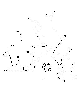
Figure 9 shows a rear view of a load bed 2 which is fixedly arranged on the
chassis 6
and which load bed 2 is thus not tiltable. To fold the tailgate 1, two power
means 22
are arranged, which power means 22 are connected to the respective second link
arm
32. Thus, depending on the shape and size of the load bed 2, the power means
22 may
be arranged so as to protrude a minimal or no distance under the load bed 2.
Such a
solution is advantageous when the load bed 2 is fixedly arranged at the
chassis and is
of the ejector bed type, as it is desirable to arrange an ejector bed as low
as possible
CA 02909509 2015-10-14
WO 2014/200410 PCT/SE2014/050632
12
above the ground. The power means 22 may according to this embodiment be
connect-
ed to the load bed 2 in the space formed between the respective wheel 8 and
the re-
spective side of the load bed 2 in the recesses 34. Thus, the wheels 8 will
protect the
power means 22 against external impact from for example protruding rock
portions in
a mine adit when the load bed 2 is advanced in the mine adit.
The components and features stated above may within the scope of the invention
be
combined between different available embodiments.