Note: Descriptions are shown in the official language in which they were submitted.
CA 02909555 2015-10-19
ENLARGEMENT OF TRACKING VOLUME BY MOVEMENT OF IMAGING BED
FIELD OF THE INVENTION
The present invention relates generally to tracking
invasive probes within the body of a patient, and
specifically to apparatus and methods for tracking probe
location within a body in a tomographic imaging system.
BACKGROUND
Medical tomographic imaging involves capturing radiation
transmitted through or emitted from the patient's body in
multiple directions, and then processing the captured
radiation to reconstruct images of structures within the
body, typically in three dimensions. Modern
tomographic
imaging techniques include, inter alia, computed tomography
(CT) based on X-ray transmission and magnetic resonance
imaging (MRI), as well as single-photon emission computed
tomography (SPECT) using gamma rays, positron emission
tomography (PET), and other methods that are known in the
art.
In a typical medical tomographic imaging system, the
patient lies on a motorized bed (also referred to as a
table), which conveys the patient through the bore of the
imaging system. The system generally controls the motion of
the bed precisely, either automatically or under operator
control, in order to position the part of the body that is of
interest within the detection volume of the system. In some
applications, the bed moves continuously at a controlled
speed during imaging, as described, for example, in U.S.
Patent 7,738,944.
Magnetic sensing systems are widely used for tracking
the position of a probe inside the body of a patient. For
1
CA 02909555 2015-10-19
example, PCT International Publication WO 1996/05768, whose
disclosure is incorporated herein by reference, describes a
locating system in which a plurality of field generators
produce AC magnetic fields, which are detected by a plurality
of sensors at the distal end of an invasive medical
instrument. Signals from the sensors are processed in order
to find the location and orientation coordinates of the
instrument. The CARTO system, produced by Biosense Webster
(Diamond Bar, California), uses this sort of magnetic sensing
to track and visualize the location of a catheter inside the
patient's body.
Magnetic sensing of catheter position may be used in
conjunction with imaging modalities, such as MRI. For
example, U.S. Patent Application Publication 2014/0094684,
whose disclosure is incorporated herein by reference,
describes a medical probe that is suitable for operating in
an MRI environment. The probe comprises a flexible insertion
tube, which has a distal end for insertion into a body
cavity, such as a section of a heart, which is imaged using
MRI techniques. A coil in
the probe may be used as a
position sensor to derive the location and orientation of the
distal end of the probe from signals generated when the coil
is in an alternating magnetic field having a known spatial
distribution. This
magnetic field is generated by coils
placed at known positions, typically below the patient's
torso.
SUMMARY
Embodiments of the present invention provide improved
methods and apparatus for tracking the location of an
invasive probe in a patient's body.
2
CA 02909555 2015-10-19
,
There is therefore provided, in accordance with an
embodiment of the present invention, a medical system,
including an imaging apparatus, which includes an array of
detectors, which define an imaging volume and are configured
to form images of a region within a body of a patient that is
positioned in the imaging volume, and a movable bed, which is
configured to transport the body of the patient through the
imaging volume. An
invasive probe is configured for
insertion into a lumen within the body of the patient. A
tracking apparatus includes a field transducer positioned in
the imaging apparatus and defining a tracking volume within
the imaging apparatus, and is configured to generate an
indication of a location of the invasive probe within the
tracking volume responsively to an interaction between the
field transducer and the invasive probe. A
controller is
coupled to control the movable bed in response to the
location of the invasive probe indicated by the tracking
apparatus.
In a disclosed embodiment, the imaging apparatus
includes magnetic resonance imaging (MRI) apparatus, and the
detectors include coils configured to receive signals from
tissues in the body in response to an applied magnetic field.
The invasive probe may include a catheter, which is
configured for insertion through a blood vessel into a heart
of the patient.
In some embodiments, the field transducer includes a
location pad, including a plurality of coils, which generate
magnetic fields within the tracking volume, and the tracking
apparatus is configured to receive signals output from the
invasive probe in response to the magnetic fields and to
process the signals in order to generate the indication of
3
CA 02909555 2015-10-19
the location of the invasive probe. The field transducer is
typically positioned so that the tracking volume overlaps the
imaging volume, and the controller is configured to register
the location of the invasive probe in a coordinate system of
the imaging apparatus and to superimpose the indication of
the registered location on the images that are produced by
the imaging apparatus.
In some embodiments, the field transducer is positioned
so that the tracking volume is fixed relative to the imaging
volume, and wherein the controller is configured to cause the
movable bed to shift in response to motion of the invasive
probe within the body of the patient so that the invasive
probe remains within the imaging volume notwithstanding the
motion. The
controller may be configured to cause the
movable bed to shift in a direction opposite to the motion of
the invasive probe and possibly to control a speed of
movement of the movable bed so as to compensate for
advancement of the invasive probe through the body.
There is also provided, in accordance with an embodiment
of the present invention, a method for imaging and tracking,
which includes positioning a field transducer of a tracking
apparatus in an imaging apparatus, which has an imaging
volume and forms images of a region within a body of a
patient that is positioned in the imaging volume while the
patient lies on a movable bed, which transports the body of
the patient through the imaging volume. A
location of an
invasive probe that has been inserted into a lumen in the
body of the patient is tracked responsively an interaction
between the field transducer and the invasive probe while the
invasive probe is within a tracking volume of the tracking
apparatus that is defined by the field transducer. The
4
CA 02909555 2015-10-19
movable bed is controlled in response to the tracked location
of the invasive probe.
There is additionally provided, in accordance with an
embodiment of the present invention, tracking apparatus for
operation in conjunction with an imaging apparatus, which has
an imaging volume and is configured to form images of a
region within a body of a patient that is positioned in the
imaging volume, and which includes a movable bed for
transporting the body of the patient through the imaging
volume. The
tracking apparatus includes an invasive probe
configured for insertion into a lumen within the body of the
patient. A field
transducer is positioned in the imaging
apparatus and defines a tracking volume within the imaging
apparatus. A
controller is configured to generate an
indication of a location of the invasive probe within the
tracking volume responsively to an interaction between the
field transducer and the invasive probe, and to control the
movable bed in response to the location of the invasive
probe.
The present invention will be more fully understood from
the following detailed description of the embodiments
thereof, taken together with the drawings in which:
BRIEF DESCRIPTION OF THE DRAWINGS
Fig. 1 is schematic pictorial illustration of an imaging
and tracking system, in accordance with an embodiment of the
present invention;
Figs. 2A and 23 are schematic side views of a patient in
an imaging and tracking system, in accordance with an
embodiment of the present invention; and
Fig. 3 is a flow chart that schematically illustrates a
method for controlling the movement of a patient bed in an
CA 02909555 2015-10-19
imaging and tracking system, in accordance with an embodiment
of the present invention.
DETAILED DESCRIPTION OF EMBODIMENTS
In some new modalities of image-guided medical
treatment, an invasive probe, such as a catheter, is inserted
into and manipulated within a patient's body while an imaging
apparatus, such as an MRI system, captures images of a region
of interest within the body in which the probe is located.
For example, a catheter may be inserted through the vascular
system into the patient's heart while three-dimensional (3D)
images of the heart are captured by MRI. Tracking apparatus,
such as the above-mentioned CARTO magnetic tracking system,
may meanwhile be used to track and indicate the location of
the catheter in the body during diagnostic and therapeutic
procedures that are carried out in this configuration.
To enable this sort of combined imaging and tracking
functionality, a field transducer, for use in tracking the
invasive probe, is placed in the bore of the imaging
apparatus. When magnetic tracking is used, for example, the
field transducer may have the form of a location pad,
comprising multiple coils, and may be fixed below the movable
bed of the imaging apparatus, on which the patient lies
during the procedure. The location coordinates of the probe
that are provided by the field transducer may be registered
with the coordinate frame of the imaging apparatus so that
the probe location can be indicated accurately on the 3D
images. For this purpose, the field transducer is positioned
so that the tracking volume that it defines overlaps with the
imaging volume that is defined by the detector array inside
the bore of the imaging apparatus.
6
CA 02909555 2015-10-19
For some procedures, however, limiting the tracking
volume to the area of the bore of the imaging apparatus can
be problematic. For
example, in many cardiological
procedures, a catheter is inserted into the body through the
femoral vein and is advanced through the vascular system into
the heart. The physician performing the procedure has a need
to observe the location of the distal end of the catheter all
the way from its entry point to the heart. The
static
tracking volume of the tracking apparatus in the bore of the
imaging apparatus may not be sufficient for this purpose.
Embodiments of the present invention that are described
herein overcome this limitation by making use of the existing
movable bed of the imaging apparatus and of the registration
between the respective coordinate frames of the imaging and
tracking apparatuses in order to extend the effective
tracking volume. These embodiments exploit the fact that the
coordinates of the movable bed in the imaging apparatus are
necessarily registered with the coordinate frame of the
imaging apparatus itself, in order to enable the imaging
apparatus to shift the patient's body precisely to the
desired location during imaging. On this
basis, the bed
coordinates can be registered relative to the coordinate
frame of the tracking apparatus, and a system controller may
thus accurately determine the probe location relative to the
bed.
On this basis, in the disclosed embodiments, the
controller applies the location of the invasive probe that is
indicated by the tracking apparatus in controlling the
movable bed so as to transport the body of the patient in a
desired manner through the imaging and tracking volumes of
the combined system. The
controller typically causes the
7
CA 02909555 2015-10-19
,
movable bed to shift in response to motion of the invasive
probe within the body of the patient so that the invasive
probe remains within the tracking volume notwithstanding the
motion of the probe. In
other words, referring to the
previous example in which a catheter is inserted through the
femoral vein into the heart, the controller may control the
bed initially to position the region of the patient's groin
in the bore of the imaging system, and may thereafter cause
the bed to shift in the direction opposite to the motion of
the catheter as the catheter is advanced up through the veins
to the heart. In
this way, the catheter always remains
within the tracking (and imaging) volume of the system. The
controller may control the speed of movement of the bed
precisely so as to compensate for advancement of the catheter
through the body.
Thus, the disclosed embodiments take advantage of the
existing features and capabilities of the imaging apparatus
in order to enlarge the effective tracking volume of the
tracking apparatus, far beyond the limited volume provided by
the field transducer itself. The
enlarged tracking volume
provides the physician with accurate location information
regarding the invasive probe throughout the patient's body at
little or no added cost relative to the costs of the
component imaging and tracking apparatuses. This
location
information may be provided to the physician by itself or in
combination with images captured by the imaging apparatus at
the different bed positions.
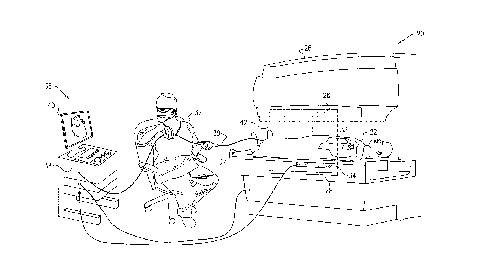
Fig. 1 is schematic pictorial illustration of an imaging
and tracking system 20, in accordance with an embodiment of
the present invention. In this example, system 20 is assumed
to comprise imaging apparatus in the form of an MRI scanner
8
CA 02909555 2015-10-19
26. A physician 32 inserts an invasive probe in the form of
a catheter 30 into the body of a patient 22, who lies on a
movable bed 24 in scanner 26. Magnetic tracking apparatus,
comprising a magnetic location pad 34 and suitable sensing
coils (not shown) within catheter 30, provides an indication
of the location of the catheter within the body. These
particular components of system 20 are shown and described
here, however, solely for the sake of concreteness and
clarity of explanation, and the principles of the present
invention may similarly be applied in systems using other
imaging and tracking modalities, as well as other sorts of
invasive probes and procedures.
As is known in the art, MRI scanner 26 comprises
magnetic field coils (not shown), including field gradient
coils, which generate a spatially-variant magnetic field
within the scanner. In
addition, scanner 26 comprises an
array of detectors, in the form of transmit/receive coils 28.
These coils radiate radio-frequency (RF) energy, which
interacts with the nuclear spins of the patient's tissue, and
detect RF signals received from the tissue as the nuclei
relax. The
detected signals are processed to generate 31J
images of the region of the patient's body that is located
inside an imaging volume 42 defined by coils 28. (The region
between coils 28 is also referred to as the "bore" of scanner
26, in reference to the central cylindrical imaging zone in
many imaging scanners.) Bed 24 may be shifted by scanner 26
so that the region of the body that is of interest is located
in imaging volume 42.
While patient 22 lies on bed 24 in scanner 26, physician
32 feeds catheter 30 through the patient's vascular system
from the femoral vein to the patient's heart 33. Location
9
CA 02909555 2015-10-19
pad 34 serves as a field transducer to generate magnetic
fields that are received by one or more sensing coils in the
distal end of catheter 30. Alternatively, the coil or coils
in the catheter may generate magnetic fields, which are
sensed by location pad 34.
Location pad 34 may be fixed in scanner 26 below bed 24.
To fit into these narrow confines, location pad 34 may
comprise multiple low-profile coils (not shown), arranged in
a horizontal plane within a housing made from an MRI-
compatible material, such as a suitable plastic. When drive
currents are applied to the coils, they generate magnetic
fields that pass through bed 24 into the body of patient 22.
Further details of this sort of location pad and its
operation in tracking catheter 30 are described, for example,
in U.S. Patent Application 14/138,654, filed December 23,
2013, whose disclosure is incorporated herein by reference.
Alternatively, other sorts of magnetic location pads may be
used to similar effect.
A console 36 drives location pad 34 and receives signals
from catheter 30 in response to the magnetic fields generated
by the location pad. A controller 38 in console 36 processes
these signals in order to derive location coordinates of
catheter 30 inside the patient's body. The
controller may
compute these coordinates using the methods described in the
above-mentioned U.S. Patent Application 14/138,654, or as is
otherwise known in the art. The
location coordinates
provided in the frame of reference of location pad 34 are
typically registered with the image coordinate frame of
scanner 26, using a suitable calibration procedure, before
bringing patient 22 into system 20. A calibration jig and
procedure that may be used for this purpose are described,
CA 02909555 2015-10-19
for example, in U.S. Patent Application 14/195,068, filed
March 3, 2014, whose disclosure is incorporated herein by
reference.
Controller 38 also receives image data from MRI scanner
26 and is able to control certain functions of the scanner,
such as movement of bed 24, using a real-time messaging
protocol or application program interface (API) provided by
scanner 26. Controller 38 is thus able to drive a display 40
on console 36 to show 3D images produced by scanner 26 and to
superimpose an indication of the location of catheter 30,
provided by the tracking apparatus, on these images. This
superimposition is made possible by the above-mentioned
registration between the coordinate frames of the tracking
apparatus (specifically of location pad 34) and of scanner
26. On this basis, controller 38 may also derive 3D maps and
local data from the signals output by catheter 30 and show
these maps and data on display 40 in registration with the 3D
images from scanner 26.
Controller 38 typically comprises a general-purpose
computer processor, with suitable interfaces and software for
carrying out the functions that are described herein. The
software may be stored in non-transitory computer-readable
media, such as optical, magnetic, or electronic memory media.
Alternatively or additionally, at least some of the functions
of controller 38 may be carried out by suitable logic (hard-
wired or programmable) or by a programmable digital signal
processor.
Figs. 2A and 2B are schematic side views of patient 22
on bed 24 in system 20, at two successive stages in the
catheterization procedure illustrated in Fig. 1, in
accordance with an embodiment of the present invention.
11
CA 02909555 2015-10-19
These figures illustrate how controller 38 is able to
effectively extend a tracking volume 50 of location pad 34 by
suitably controlling the movement of bed 24.
The size and extent of tracking volume 50 are determined
generally by the size and position of location pad 34 within
scanner 26.
Typically, as illustrated in Figs. 2A and 2B,
location pad 34 is positioned so that tracking volume 50
overlaps imaging volume 42 (thus facilitating the
presentation of registered data, as described above). The
geometrical constraints of scanner 26 and location pad 34
generally make it infeasible to extend tracking volume 50
much beyond the bounds of imaging volume 42. Consequently,
as illustrated in Fig. 2B, tracking volume 50 is typically
large enough to encompass an area of the thorax of patient 22
that contains heart 33 while scanner 26 images this area, but
cannot concurrently encompass the area of the patient's groin
and abdomen through which catheter 30 is inserted into the
body.
To remedy this problem, while physician 32 is inserting
and advancing catheter 30 through the veins in the groin and
abdomen, controller 38 instructs scanner 26 to shift bed 24
so that the groin and abdomen of patient 22 are located in
tracking volume 50 of location pad 34, as shown in Fig. 2A.
Controller 38 is thus able to track the location of catheter
30 during this stage. (Scanner 26 may optionally be operated
to capture images of this region of the body, as well, if
desired.) As physician 32 advances catheter 30 toward heart
33, controller 38 tracks the movement of the catheter and
instructs scanner 26 to shift bed 24 in the opposite
direction, so that the catheter remains within tracking
12
CA 02909555 2015-10-19
volume 50 notwithstanding the movement, until the catheter
reaches heart 33 as shown in Fig. 2B.
Consequently, the effective tracking volume of the
tracking apparatus in system 20 is considerably larger than
the actual, physical tracking volume 50 provided by location
pad 34, and includes both the abdomen (Fig. 2A) and the
thorax (Fig. 2B) of patient 22. When physician 32 withdraws
catheter 30 from the body, controller 38 may cause bed 24 to
move back in the opposite direction in order to track the
exit path of the catheter through the vascular system.
Fig. 3 is a flow chart that schematically illustrates a
method for controlling the movement of bed 24 in system 20,
in accordance with an embodiment of the present invention.
As noted earlier, although this method is described, for the
sake of clarity, with specific reference to the elements of
system 20, it may similarly be applied in other systems with
other sorts of imaging and tracking capabilities. The method
implements a closed-loop control algorithm to shift the
position of bed 24 relative to location pad 34, and thus to
move patient 22 in such a manner that the distal end of
catheter 30 will always stay in tracking volume 50, as well
as in imaging volume 42.
As an initial step, location pad 34 is placed in the
center of the "bore" of MRI scanner 26, at a pad placement
step 60. In other
words, location pad 34 is positioned so
that its tracking volume 50 overlaps imaging volume 42, as
described above.
Controller 38 registers the image
coordinate system of scanner 26 with the location coordinate
system of location pad 34, at a registration step 62. In
this manner, location-based data relating to catheter 30 may
be superimposed on images generated by scanner 26, and
13
CA 02909555 2015-10-19
controller 38 may also use the catheter location in
controlling the position of bed 24.
Based on the signals generated by interaction of
catheter 30 with location pad 34, controller 38 acquires the
current location coordinates of the catheter, at a position
acquisition step 64.
Controller 38 then calculates the
distance between the distal end of catheter 30 and the center
of location pad 34 (or equivalently, the center of tracking
volume 50), at a distance calculation step 66. The
controller evaluates this distance to determine whether the
catheter is near the center of tracking volume 50 or close to
its edge, at a location checking step 68. As long
as the
catheter is at least some threshold distance away from the
edges of the tracking volume, controller 38 returns to step
64 without invoking any movement of bed 34.
Upon finding at step 68 that the distal end of catheter
30 is close to an edge of tracking volume 50, however,
controller 38 invokes corrective movement of bed 34. For
this purpose, controller 38 may calculate the speed of bed
movement that will best compensate for the movement of
catheter 30 through the body of patient 22, at a speed
calculation 70. This speed may be related, for example, to
the speed at which physician 32 is advancing or retracting
the catheter through the vascular system.
Controller 38
instructs scanner 26 to shift bed 24 at the appropriate speed
in the direction opposite to the direction of catheter
motion, at a bed movement step 72.
Controller 38 then returns to step 64, and the process
continues iteratively until the procedure is completed.
As noted earlier, although the embodiments described
above relate to magnetic tracking of a catheter in an MRI-
14
CA 02909555 2015-10-19
based system, the principles of the present invention may
similarly be applied using other imaging modalities in which
the patient is transported through the imaging apparatus by a
movable bed. For
example, in alternative embodiments (not
shown in the figures), an invasive probe may be tracked in
the manner described herein in conjunction with CT, PET,
SPECT or other imaging modalities that are known in the art.
Additionally or alternatively, the probe location may be
tracked, mutatis mutandis, using other technologies that are
known in the art, such as ultrasonic or electrical tracking
techniques. The principles of the present invention may be
applied not only in cardiac catheterization, but also in
tracking invasive probes of other types in diagnostic and
therapeutic procedures applied to other organs.
It will be appreciated that the embodiments described
above are cited by way of example, and that the present
invention is not limited to what has been particularly shown
and described hereinabove. Rather, the scope of the present
invention includes both combinations and subcombinations of
the various features described hereinabove, as well as
variations and modifications thereof which would occur to
persons skilled in the art upon reading the foregoing
description and which are not disclosed in the prior art.