Note: Descriptions are shown in the official language in which they were submitted.
CA 02910402 2015-10-26
WO 2014/182547
PCT/US2014/036478
FRACTURING USING RE-OPENABLE SLIDING SLEEVES
BACKGROUND
[0001] In the recovery of downhole hydrocarbons, it is useful to inject fluids
or fluid slurries into through the wellbore and to the hydrocarbon bearing
formation to fracture or otherwise treat the wellbore or the hydrocarbon
bearing formation. Typically, accessing a hydrocarbon bearing formation
begins with drng a wellbore through at least one hydrocarbon bearing
zone. After the well is drilled the well is completed by inserting a casing
into
the wellbore, cementing the casing in the wellbore, and opening ports in the
casing through which fluids may be injected into or removed from the
formation. Although in some cases the casing is not cemented into the
wellbore. In such a case packers may be used for zone isolation,
[0002] It may be desirable that a zone of a wellbore adjacent to a targeted
hydrocarbon bearing formation be isolated from other zones of the wellbore.
For example, if such a targeted zone is not isolated, the fracturing fluid
that
is pumped down the weilbore, will flow through the ports and then will travel
along the exterior of the casing out of the targeted zone into areas that are
not hydrocarbon bearing formations and perhaps even into other separate
hydrocarbon bearing formations quickly overcoming the ability of the casing
to transport the fluid into the formations and the ability of the pumps to
supply the fluid at pressure sufficient to fracture the formation. Similarly,
annular fluid flow between the wellbore and casing may result in reduced
recovery of fluids, loss of treatment fluids, or infiltration of undesired
materials into a targeted or untargeted zones.
[0003] Usually after a zone has been isolated, ports in the casing may be
opened to allow for the injection of fluids or slurries into as well as the
removal of fluids or slurries from the hydrocarbon bearing formation. It may
be desirable that the ports may be selectively opened or closed. Typically
the ports are installed in the well in a closed condition by use of sliding
sleeves Typical sliding sleeve valves comprise a sleeve having
1
CA 02910402 2015-10-26
WO 2014/182547
PCT/US2014/036478
circumferential seals such as 0-rings at the top and bottom edges thereof to
seal against a wall of the casing. Thus, when the sleeve is positioned over
a port, the sleeve substantially prevents fluid communication between the
interior of the casing and the hydrocarbon bearing formation through the
port. The port may be opened by moving the sliding sleeve so that the
sliding sleeve is located above or below the port or at ieast aligning a port
in the sliding sleeve with the port in the casing thereby allowing fluid flow
into or out of the desired zone.
[0004] More specifically, a tubular assembly is put together on the rig floor
prior to being lowered into the well bore. If the operator does not plan to
cement the tubular assembly into the wellbore annular zonal isolation
packers will also be installed along the length of the tubular assembly.
Typically a packer will be installed both above and below each port and
spaced far enough apart to straddle a particular hydrocarbon bearing
formation or at least a particular zone of a hydrocarbon bearing formation.
In many instances a single packer may serve as the upper packer on one
zone as well as the lower packer on an adjacent zone.
[0005] The tubular assembly is then lowered into the wellbore so that a port
is adjacent to the desired zone, preferably hydrocarbon bearing formation
with packers both above and below the zone to straddle the zone.
[0006] With the tubular assembly in place the operator then runs an internal
packer or plug into the tubular assembly using a second tubular assembly,
typically coil tubing. The operator will then land the plug below the lowest
port. The plug is then set and the operator disconnects the coil tubing from
the plug. Once disconnected from the plug the coil tubing connector is
moved up the wellbore and is located adjacent the lowest sliding sleeve
where the coil tubing connector latches into the sliding sleeve. The sliding
sleeve is then moved from its closed position to its open position. Fluid,
typically a hydraulic fracturing slurry, is pumped down the tubular assembly
with the tubular assembly plugged below and all of the other sliding sleeves
2
CA 02910402 2015-10-26
WO 2014/182547
PCT/US2014/036478
closed the fluid is forced out of the open sliding sleeve port and into the
isolated zone. Once the treatment is complete the pumps at the surface are
turned off, the operator disconnects the coil tubing connector from the
sliding sleeve and lowers the coil tubing and the coil tubing connector to the
packer. The packer is then unset and raised until it is above the lowest port
and sliding sleeve but below the next higher port and sliding sleeve. The
packer is then reset and the process of treating the well is repeated until
each zone has been treated. Unfortunately, when a sliding sleeve is opened
or closed the seals between the sleeve in the casing are damaged so that
thereafter when the sliding sleeve is closed it will leak. Because the sliding
sleeves leak when closed after being opened the operator can no longer
rely on sliding sleeves to seal for in the event that the operator desired to
treat or otherwise service a particular zone.
SUMMARY
[0007] A method has been invented which provides for selective
communication to a wellbore for fluid treatment while overcoming the
limitations of previous zone isolation methods. In one embodiment of the
invention the method provides for selective injection of treatment fluids
wherein fluid is injected into selected intervals of the wellbore, while other
intervals are closed.
[0008] In another aspect, the method provides for running in a fluid
treatment string, the fluid treatment string having ports substantially closed
against the passage of fluid, but when opened permit fluid flow into or out of
the wellbore. The methods of the present invention can be used in various
borehole conditions including open holes, cased holes, vertical holes, or
deviated holes.
[0009] In one embodiment a tubular assembly is assembled on the surface
incorporating a ported sliding sleeve subassembly as described in US
3
patent publication no. 2011/0204273 and invented by Kristoffer Braekke.
The ported sliding sleeve subassembly
may be opened and closed as often as desired without substantial leaking
The tubular assembly is then run into the wellbore with each ported sliding
sleeve subassembly in the closed position and such that each ported sliding
sleeve subassembly is generally adjacent to a desired isolated zone. Zone
isolation may be accomplished by cementing the tubular assembly into the
well by the use of annular packers along the length of the tubular assembly.
[0010] When the operator desires to stimulate or otherwise treat the well a
shifting tool is run into the well on coil tubing until the shifting tool is
adjacent
the desired ported sliding sleeve subassembly. Typically the desired ported
sliding sleeve subassembly will be located closest to the bottom of the well.
In some instances the shifting tool may be pumped down on wireline or e-
line or the shifting tool may be carried down by a tractor. Once the shifting
tool is located adjacent to the desired ported sliding sleeve subassembly the
shifting tool will latch into a corresponding profile on the sliding sleeve.
The
shifting tool that ships sliding sleeve open to expose the port. Once the port
in the sliding sleeve subassembly is exposed the operator may treat or frac
the well through the open ports, without setting an internal packer in the
casing although in some instances the operator may desire to set a packer
or permanent plug below the lowest ported sliding sleeve subassembly or
otherwise seal off the bottom of the casing.
[0011] After the formation has been treated through the ported sliding sleeve
subassembly the operator may then use the shifting tool to close the ported
sliding sleeve subassembly. The operator then disconnects the shifting tool
from the ported sliding sleeve subassembly and then proceeds to any other
ported sliding sleeve subassembly as desired. In some instances a single
ported sliding sleeve subassembly may be used in each isolated zone.
However, in other cases multiple ported sliding sleeve subassemblies may
be used in a single zone and and even other cases a single ported sliding
sleeve subassembly may be used in a single zone while multiple ported
4
CA 2910402 2019-10-18
CA 02910402 2015-10-26
WO 2014/182547
PCT/US2014/036478
sliding sleeve subassemblies may be used in another zone all within the
same well.
[0012] In another embodiment of a wellbore servicing system, a tubular
assembly has a first resealable valve and at least a second resealable valve.
The first resealable valve has a first profile and the second resealable valve
has a second profile. A shifting tool selectively engages the first profile
and
the second profile and selectively opens or closes the first resealable valve
and selectively opens or closes the second resealable valve. The tubular
assembly may utilize cement or at least two packers for zonal isolation. In
some instances the packers may be swab cup packers or they may be
swellable packers. The first resealable valve and the at least second
resealable valve may have a substantially cylindrical outer valve housing
including radially extending side ports and an inner sliding sleeve mounted
axially movable and rotationally locked inside the valve housing. The sliding
sleeve may also have a first sealing means, a second sealing means, and
a third sealing means. The sealing means are all disposed around the entire
circumference of the sliding sleeve and in contact with an inner sealing
surface of the valve housing. The axial distance between the first and
second sealing means is greater than the length of the valve housing
comprising the side ports, and axial distance between the second and third
sealing means is greater than the length of the valve housing comprising
the side ports. Additionally, the first sealing means is made stiffer than the
second and third sealing means and the first sealing means is firmer
retained than the second and third sealing means. The sliding sleeve is fixed
to a radially flexible latch ring abutting a first inner shoulder on the inner
sealing surface of the valve housing when the valve is in a first, closed
position, and abutting a second inner shoulder on the inner sealing surface
of the valve housing when the valve is in a second, open position axially
displaced from the first closed position. The axial force required to move the
sliding sleeve between its first and second positions must be sufficient to
overcome a radially spring force from the latch ring. The valve typically has
CA 02910402 2015-10-26
WO 2014/182547
PCT/US2014/036478
a scraping ring disposed between the sliding sleeve and the inner sealing
surface of the valve housing. The sliding sleeve typically has a first
labeling
means where the valve housing is firmly connected to a second labeling
means; and the axial distance between the first and second labeling means
indicates whether the sliding sleeve opens or closes for the radial side
ports.
[0013] In another embodiment of the wellbore servicing system, a tubular
assembly typically has a first resealable valve and at least a second
resealable valve. The first resealable valve may be selectively actuable
between an open condition and a closed condition and the at least second
resealable valve may be selectively actuable between an open condition
and a closed condition. The first resealable valve and the at least second
resealable valve in the open condition allow a fluid to flow between an inner
diameter of the tubular assembly and an outer diameter of the tubular
assembly. The first resealable valve and the at least second resealable
valve may be selectively actuable by hydraulic control lines, by an electric
motor, or by a shifting tool. In certain instances zonal isolation may be
provided by cement or at least two packers. The packers may be swab cup
packers, swellable packers, or any other style packer known in the industry.
The first resealable valve and the at least second resealable valve may have
a substantially cylindrical outer valve housing including radially extending
side ports and an inner sliding sleeve mounted axially movable and
rotationally locked inside the valve housing. The sliding sleeve may have a
first sealing means, a second sealing means, and a third sealing means,
which sealing means are all disposed around the entire circumference of
the sliding sleeve and in contact with an inner sealing surface of the valve
housing. The axial distance between the first and second sealing means is
greater than the length of the valve housing having the side ports, and axial
distance between the second and third sealing means is greater than the
length of the valve housing having the side ports. Typically the first sealing
means is made stiffer than the second and third sealing means and the first
sealing means is firmer retained than the second and third sealing means.
6
CA 02910402 2015-10-26
WO 2014/182547
PCT/US2014/036478
The sliding sleeve is fixed to a radially flexible latch ring abutting a first
inner
shoulder on the inner sealing surface of the valve housing when the valve
is in a first, closed position, and abutting a second inner shoulder on the
inner sealing surface of the valve housing when the valve is in a second,
open position axially displaced from the first closed position. The axial
force
required to move the sliding sleeve between its first and second positions
must be sufficient to overcome a radially spring force from the latch ring.
The valve has a scraping ring disposed between the sliding sleeve and the
inner sealing surface of the valve housing. The sliding sleeve may have a
first labeling means and the valve housing is firmly connected to a second
labeling means. The axial distance between the first and second labeling
means indicates whether the sliding sleeve opens or closes for the radial
side ports.
[0014] In another embodiment for a method of servicing a wellbore. A
tubular assembly having a first resealable valve and an at least second
resealable valve into a wellbore. The first resealable valve may be
selectively actuable between an open condition and a closed condition. The
at least second resealable valve may be selectively actuable between an
open condition and a closed condition; and where the first resealable valve
and the at least second resealable valve in the open condition allow a fluid
to flow between an inner diameter of the tubular assembly and an outer
diameter of the tubular assembly. Any of the first resealable valve or at
least
second resealable valve may be selectively actuated from a closed
condition to an open condition. The adjacent formation zone is then treated.
Any of the first resealable valve or at least second resealable valve may be
selectively actuated from an open condition to a closed condition. The first
resealable valve may be at least two resealable valves in a single isolated
zone. The at least second resealable valves may be at least two resealable
valves in a single isolated zone. The first resealable valve and the at least
second resealable valve are each selectively actuable by hydraulic control
lines, by electric motor, or by a shifting tool. The tubular assembly may
utilize
7
CA 02910402 2015-10-26
WO 2014/182547
PCT/US2014/036478
cement, or at least two packers for zonal isolation. The packers may be
swab cup packers, swellable packers, or any other type packer known in the
industry. The first resealable valve and the at least second resealable valve
may have a substantially cylindrical outer valve housing including radially
extending side ports and an inner sliding sleeve mounted axially movable
and rotationally locked inside the valve housing. The sliding sleeve may
have a first sealing means, a second sealing means, and a third sealing
means. The sealing means are all disposed around the entire circumference
of the sliding sleeve and in contact with an inner sealing surface of the
valve
housing. The axial distance between the first and second sealing means is
greater than the length of the valve housing having side ports, and axial
distance between the second and third sealing means is greater than the
length of the valve housing having side ports. The first sealing means is
made stiffer than the second and third sealing means and the first sealing
means is firmer retained than the second and third sealing means. The
sliding sleeve is fixed to a radially flexible latch ring abutting a first
inner
shoulder on the inner sealing surface of the valve housing when the valve
is in a first, closed position, and abutting a second inner shoulder on the
inner sealing surface of the valve housing when the valve is in a second,
open position axially displaced from the first closed position. The axial
force
required to move the sliding sleeve between its first and second positions
must be sufficient to overcome a radially spring force from the latch ring.
The valve further may also have a scraping ring between the sliding sleeve
and the inner sealing surface of the valve housing. In some instances the
sliding sleeve may have a first labeling means with the valve housing firmly
connected to a second labeling means and where the axial distance
between the first and second labeling means indicates whether the sliding
sleeve opens or closes for the radial side ports.
BRIEF DESCRIPTION OF THE DRAWINGS
[0015] Figure 1 depicts setting the internal packer in a fracturing process.
8
CA 02910402 2015-10-26
WO 2014/182547
PCT/US2014/036478
[0016] Figure 2 depicts engaging the sliding sleeve profile in a fracturing
process.
[0017] Figure 3 depicts fracturing is zone in a fracturing process.
[0018] Figure 4 depicts unsetting the packer in a fracturing process.
[0019] Figure 5 depicts moving up hole to the next sliding sleeve in a
fracturing process.
[0020] Figure 6 depicts a tubular assembly having resealable valves.
[0021] Figure 7 depicts the tubular assembly with the lowest valve shifted
open.
[0022] Figure 8 depicts the tubular assembly with the lowest valve re-
sealed.
[0023] Figure 9 depicts the tubular assembly with the disconnect at the
next desired valve.
[0024] Figure 10 depicts the tubular assembly with the next desired valve
shifted open.
[0025] Figure 11 depicts a cross-section of the valve.
[0026] Figure 12 is an enlarged view of the figure 11 valve section "B."
[0027] Figure 13 is an enlarged view of the figure 11 valve section "C."
[0028] Figure 14 depicts the scraping ring of figure 11.
DETAILED DESCRIPTION OF THE PRESENT INVENTION
[0029] Referring to Figure 1, a wellbore 10 is shown extending vertically
from the surface 20 with a heel generally 30 and a toe generally 40. The
heel 30 is typically that section of the well where the wellbore 10
transitions
from being essentially vertical to being more or less horizontal and
extending down to the bottom or lower end of the well 10 at the toe 40.
9
CA 02910402 2015-10-26
WO 2014/182547
PCT/US2014/036478
Extending into the well is a tubular assembly 12 is made up on the surface
and then run down into the wellbore 10. The tubular assembly 12 typically
has along its length external annular packers for zone isolation.
[0030] Figure 1 depicts three formation zones generally 22, 24, and 26. A
first packer 32 resides past the lower end of zone 22 while a second packer
34 resides beyond the upper end of formation zone 22. With packers 32 and
34 straddling formation zone 22, formation zone 22 is isolated from both the
lower end of the wellbore 10 and formation zone 24. Packer 34 resides past
the lower end of formation zone 24 while packer 36 resides beyond the
upper end of formation zone 24. With packers 34 and 36 straddling
formation zone 24, formation zone 24 is isolated from both formation zone
24 and zone 26. Packer 36 resides past the lower end of formation zone 26
while packer 38 resides beyond the upper end of formation zone 26. With
packers 36 and 38 straddling formation zone 26, formation zone 26 is
isolated from both formation zone 26 and from the wellbore 10 above packer
38.
[0031]The tubular assembly 12 also has sliding sleeves 42, 44, and 46
between the packers 32, 34, 36, and 38 to close off ports in the tubular
assembly that would otherwise allow access to the annular area outside the
tubular assembly 12 and thus to the formation zones 22, 24, and 26. Any of
the packers mentioned herein may be swab cup packers, swellable packers,
or any other packer known in the industry. Each port and sliding sleeve may
be positioned along the tubular assembly 12 to be approximately adjacent
each of the formation zones 22, 24, and 26 when the tubular assembly 12
is properly positioned in the wellbore 10.
[0032] Figures 1 ¨ 5 use like reference numerals for like structures. Figure
2 depicts the first stage in a fracturing operation. With the tubular assembly
12 properly located and secured in wellbore 10, a second tubular assembly
typically coil tubing 50 is run into the tubular assembly 12. At the lower end
of the coil tubing 50 a disconnect 52 is attached to an internal packer or
plug
CA 02910402 2015-10-26
WO 2014/182547
PCT/US2014/036478
54. The disconnect 52 will typically consist of a setting tool for setting and
releasing packer 54 as well as a profile latch to latch into and release the
sliding sleeves 42, 44, and 46. While typically the second tubular assembly
is coil tubing any type of tubing could be used. In addition the second
tubular
assembly could be replaced by slick line or e-line where the disconnect 52
is pumped down the tubular assembly 12 or is carried down the tubular
assembly 12 by a tractor or other suitable device.
[0033] Once the packer 54 is located in the tubular assembly 12 below
sliding sleeve 42 the packer 54 may be set. Once the packer 54 is set, the
disconnect 52 is released from the packer 54 and moved uphole until the
disconnect 52 is located adjacent profile 62 of sliding sleeve 42. Once
disconnect 52 is located adjacent profile 62 of sliding sleeve 42 the
disconnect will latch into profile 62. After latching into profile 62 the
operator
will open sliding sleeve 42.
[0034] Figure 3 depicts sliding sleeve 42 in its open position allowing fluid
to flow through the interior of the tubular assembly 12 as depicted by arrow
70 and out into formation zone 22 as indicated by arrows 72 and 74 to
fracture or otherwise treat formation zone 22.
[0035] As depicted in figure 4, once the fracturing operation is complete the
pumps at the surface 20 are turned off so that fluid no longer flows out into
the formation zone 22. The disconnect 52 is released from profile 62 in
sliding sleeve 42. The disconnect 52 is then moved downhole until it re-
engages with internal packer 54. The disconnect 52 that releases internal
packer 54 from the tubular assembly 12.
[0036] As depicted in figure 5, the coil tubing 50, the disconnect 52, and the
internal packer 54 have been moved together to a position above sliding
sleeve 42 but below sliding sleeve 44. The packer 54 is then reset in the
tubular assembly 12 to block any fluid flow through the internal bore of the
tubular assembly 12 past the packer 54. The disconnect 52 is then released
11
from packer 54 and moved upward in the tubular assembly 12 until it is
adjacent profile 64 of sliding sleeve 44.
[0037]The fracturing process or other treatment of the wellbore 10
continues with the internal packer 54 being set below a sliding sleeve, the
disconnect releases the packer 54, moving the disconnect to engage the
profile in the sliding sleeve, opening the sliding sleeve, fracturing the
formation, releasing the disconnect from the profile in the sliding sleeve, re-
engaging the packer, unsetting the packer, moving the packer, and
repeating until each sliding sleeve has been opened and each formation
zone is treated.
[0038] Figure 6 through 10 depict an embodiment of the present invention
utilizing a valve which is a reclosable, leak resistant valve as described in
US patent publication no. 2011/0204273 invented by Kristoffer Braekke.
Figures 6 ¨ 10 use like reference
numerals for like structures.
[0039] Referring to Figure 6, a wellbore 100 is shown extending vertically
from the surface 20 with a heel generally 130 and a toe generally 140. The
heel 130 is typically that section of the well where the wellbore 100
transitions from being essentially vertical to being more or less horizontal
and extending down to the bottom or lower end of the well 100 at the toe
140. Extending into the well is a tubular assembly 112 made up on rig 114
at the surface 120 and then run down into the wellbore 100. The tubular
assembly 112 typically has along its length external annular packers for
zone isolation.
[0040] Figure 6 depicts three formation zones generally 122, 124, and 126.
A first packer 132 resides past the lower end of zone 122 while a second
packer 134 resides beyond the upper end of formation zone 122. With
packers 132 and 134 straddling formation zone 122, formation zone 122 is
isolated from both the lower end of the wellbore 100 and formation zone
124. Packer 134 resides past the lower end of formation zone 124 while
12
CA 2910402 2019-10-18
CA 02910402 2015-10-26
WO 2014/182547
PCT/US2014/036478
packer 136 resides beyond the upper end of formation zone 124. With
packers 134 and 136 straddling formation zone 124, formation zone 124 is
isolated from both formation zone 124 and zone 126. Packer 136 resides
past the lower end of formation zone 126 while packer 138 resides beyond
the upper end of formation zone 126. With packers 136 and 138 straddling
formation zone 126, formation zone 126 is isolated from both formation zone
126 and from the wellbore 100 above packer 138.
[0041] The tubular assembly 112 also has valves 142, 144, and 146
between the packers 132, 134, 136, and 138 to close off ports in the tubular
assembly 112 that would otherwise allow access to the annular area outside
the tubular assembly 112 and thus to the formation zones 122, 124, and
126. Each port and valve may be positioned along the tubular assembly to
be approximately adjacent each of the formation zones 122, 124, and 126.
In some instances a float shoe 180 may be placed on the lower end of
tubular assembly 112 to prevent fluid from flowing from inside of the tubular
assembly 112 through the lower end near the toe of the tubular assembly
140 and into the well 100. The float shoe 180 may be a one-way valve or
any other device to prevent fluid from flowing from the inside of the tubular
assembly 112 to the outside of the tubular assembly 112.
[0042] Figure 7 depicts the tubular assembly 112 with the disconnect 152
latched into profile 162 of valve 142. With the disconnect 152 latched into
profile 162 the valve 142 is depicted as having been moved from its closed
position to the open position where port 164 is open allowing fluid to flow
from the interior of the tubular assembly 112 as depicted by arrow 170 to
flow out ports 164 as depicted by arrow's 172 and 174 and into formation
zone 122 to fracture or otherwise treat formation zone 122.
[0043] Figure 8 depicts the wellbore 100 after formation zone 122 has been
treated where the formation zone 122 has fractures 182. The disconnect
162 on the end of coral tubing 150 that is latched into profile 162 of valve
142 is used to close port 164 with valve 142.
13
CA 02910402 2015-10-26
WO 2014/182547
PCT/US2014/036478
[0044]As depicted in figure 9 the disconnect 152 is released from profile
162 on valve 142 and is moved uphole to engage profile 165 of valve 144.
[0045] Figure 10 depicts the disconnect 152 engaged with profile 162 after
having shifted the valve 142 from its closed position to the open position
where port 166 is open allowing fluid to flow from the interior of the tubular
assembly 112 as depicted by arrow 176 to flow out ports 166 as depicted
by arrow's.
[0046] With the disconnect 152 latched into profile 162 the valve 142 is
depicted as having been moved from its closed position to the open position
where port 164 is open allowing fluid to flow from the interior of the tubular
assembly 112 as depicted by arrow 170 to flow out ports 164 as depicted
by arrow's 172 and 174 and into formation zone 122 to fracture or otherwise
treat formation zone 122.
[0047]The fracturing process or other treatment of the wellbore 100
continues where the disconnect 152 engages the latch on a valve, opens
the valve to expose the port, fracturing or otherwise treating the formation
zone adjacent the port through the port, closing the valve to seal the port,
disengaging the disconnect 152 from the latch on a valve, moving the
disconnect until the disconnect is adjacent the next desired valve, and
engaging the next desired valve. The process is repeated until each desired
valve has been opened and closed and each desired formation zone is
treated.
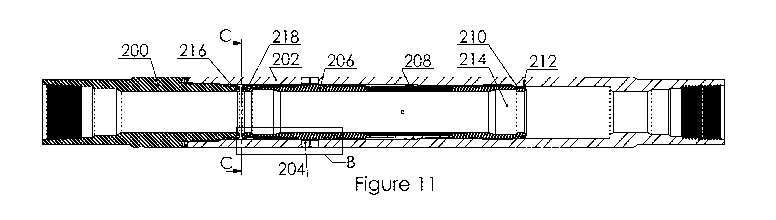
[0048] Figure 11 depicts a longitudinal cross sectional view of a valve
utilized in the invention. In figure 11, the valve is shown in a closed state.
An end part 200 connected to a valve housing 202 form the outer shell of
the valve. The valve housing 202 comprises radial side ports 204. An inner
sliding sleeve 206 can be moved axially inside the valve housing 202 in
order to open or close the radial side ports. As can be best seen in figure
12, the sliding sleeve 206 has no ports. Rather, the edge of the sleeve 206
is moved past the housing ports 204 to reach the open position. The inner
14
CA 02910402 2015-10-26
WO 2014/182547
PCT/US2014/036478
sliding sleeve 206 is prevented from rotating in the valve housing 202
because it may become necessary to rotate the disconnect or activating tool
(not shown) if it should become stuck.
[0049] In figure 11, a flexible latch ring 208 connected to the sliding sleeve
206 abuts an inner shoulder along a circumference of the valve housing
202. In order to open the valve, the sliding sleeve 206 must be pulled
towards the ring 208 (to the right in figure 11) with sufficient force to
compress the latch ring 208 radially. A corresponding shoulder is provided
for keeping the sliding sleeve 206 in its open position by means of the same
latch ring 208. Hence, the latch ring 208 prevents the sliding sleeve 206
from being swept along with fluid flowing in the central bore, and thus from
being opened or closed unintentionally.
[0050] At the right hand side of figure 11, a support ring 210, a scraping
ring
212 and a groove 214 for an opening-closing tool. The activating tool (not
shown) is inserted into the pipe to move the sliding sleeve 206 between the
closed and the open position.
[0051] The valve housing 202 and sliding sleeve 206 can each be provided
with a label (216, 218), e.g. fixed permanent magnets. When the valve is
closed, as shown in figure 11, the distance between the two
labels/permanent magnets is less than when the valve is open. A difference
between, for example 1 inch and 4 inches, between these labels or
permanent magnets is relatively easy to detect, and can be used as an
indication of whether the valve is open or closed.
[0052] Figure 12 is an enlarged view of the section marked "B" in figure 11.
The mounting rings 220, 222, and 224 retain the seals 226 and 228. When
the valve is opened by moving the sliding sleeve 206 to the right in figures
11 and 12, the seal 226 will have passed the radial side ports 204 while the
seal 228 still seals against the inner surface of the valve housing 202. The
seal 228 may advantageously be manufactured from a stiffer material than
the seal 226, and it is retained such that it is not torn out by the pressure
CA 02910402 2015-10-26
WO 2014/182547
PCT/US2014/036478
difference across it when the seal 226 is on one side and the seal 228 is on
the other side of the radial side ports 204.
[0053] The side ports 204 can be designed with different diameters for
different purposes, e.g. with larger diameters for hydraulic fracturing than
for
production. The inner surfaces of the valve may also be hardened, e.g. for
the purpose of hydraulic fracturing.
[0054] Scraping rings 230 and 232 remove deposits and scaling from the
inner surface of the valve housing 202 when the valve has been open for a
period of time and is to be closed. An isometric view of scraping rings 230
and 232 is shown in figure 14, where it is apparent that the scraping rings
230 into 32 comprise scraping lobes separated by notches in the ring. The
scraping rings 230 and 232 in figure 12 are both of the type shown in figure
14, but rotated relative to each other such that the lobes of ring 232
overlaps
the notches on ring 230 and scrapes the parts of the valve housing 202 that
are not scraped by the lobes on scraping ring 220.
[0055]The nut 234 is threaded to the sliding sleeve 206, and retains the
parts 220, 222, 224, 226, 228, 230, and 232 described above. Support rings
240 retain a seal 242, sealing the valve opposite the side ports 204 relative
to the seals 226 and 228, i.e. such that the side ports 204 are axially
localized between the seals 226 and 242.
[0056] The side ports can be manufactured from a hard material, e.g.
tungsten carbide, such that the valve withstands the wear from the ceramic
balls used in hydraulic fracturing.
[0057] Figure 13 shows a cross section of the valve through C-C on figure
11. The sliding sleeve 206 is slidably mounted in the valve housing 202, and
overlapping scraping rings 230 and 232 are retained on the sliding sleeve
206 by the nut 234.
16
CA 02910402 2015-10-26
WO 2014/182547
PCT/US2014/036478
[0058] Figure 14 shows a scraping ring 230 or 232 for mounting on the
sliding sleeve 206 in order to scrape off deposits and the like to ensure
sufficient sealing.
[0059] While the embodiments are described with reference to various
implementations and exploitations, it will be understood that these
embodiments are illustrative and that the scope of the inventive subject
matter is not limited to them. Many variations, modifications, additions and
improvements are possible.
[0060] Bottom, lower, or downward denotes the end of the well or device
away from the surface, including movement away from the surface. Top,
upwards, raised, or higher denotes the end of the well or the device towards
the surface, including movement towards the surface. While the
embodiments are described with reference to various implementations and
exploitations, it will be understood that these embodiments are illustrative
and that the scope of the inventive subject matter is not limited to them.
Many variations, modifications, additions and improvements are possible.
[0061] Plural instances may be provided for components, operations or
structures described herein as a single instance. In general, structures and
functionality presented as separate components in the exemplary
configurations may be implemented as a combined structure or component.
Similarly, structures and functionality presented as a single component may
be implemented as separate components. These and other variations,
modifications, additions, and improvements may fall within the scope of the
inventive subject matter.
17