Note: Descriptions are shown in the official language in which they were submitted.
81792543
IMPLANT RECHARGER HANDSHAKING SYSTEM AND METHOD
CROSS-REFERENCES TO RELATED APPLICATIONS
[0001] This application claims the benefit of U.S. Provisional Application No.
61/819,453,
entitled "IMPLANT RECHARGER HANDSHAKING MECHANISM," and filed on
May 3, 2013.
BACKGROUND
[0002] The prevalence of use of medical devices in treating ailments is
increasing with time. In
many instances, and as these medical devices are made smaller, these medical
devices are
frequently implanted within a patient. To the extent that these devices use an
implanted power
source to power themselves, the recharging of the implanted power source can
be a frequent and
tedious task.
[0003] In many instances, device and tissue heating can be a significant
concern with
rechargeable, implantable medical devices. These heating concerns particularly
arise during
recharging. Specifically if the charge field is too weak, the implantable
medical device will not
quickly recharge, however, if the charge field is too strong, the implantable
medical device may
overheat, thereby causing irnplantee discomfort, and potentially injuring the
imp lantee.
Accordingly, systems, methods, and devices are desired to improve recharging
of implantable
medical devices.
BRIEF SUMMARY
[0004] One aspect of the present disclosure relates to a method of charging an
energy storage
device of an implantable pulse generator using an external charger. The method
includes
wirelessly receiving at the external charger an identifier corresponding to
the implantable pulse
generator, wfrelessly receiving at the external charger information from the
implantable pulse
generator corresponding to a first sensed electrical field strength, at the
external charger,
CA 2910984 2019-05-06
CA 02910994 201.5-10-29
WO 2014/179813 PCT/US2014/036853
changing the strength of the electrical field, after changing the strength of
the electrical field,
wirelessly receiving at the external charger information from the implantable
pulse generator
corresponding to a second sensed electrical field strength, and in response to
the received
information corresponding to the first and second sensed electrical fields,
charging the energy
storage device of the implantable pulse generator using the external charger.
[0005] In some embodiments, the method includes setting a first strength of
the electrical field
at the external charger, and in some embodiments, the first strength of the
electrical field set at
the external charger is zero, while in other embodiments, the first strength
of the electrical field
set at the external charger is non-zero. In some embodiments, charging the
energy storage device
of the implantable pulse generator further includes changing the strength of
the electrical field to
a third strength at the external charger. In some embodiments, the method
includes determining
the third strength of the electrical field, which third strength of the
electrical field can be, for
example, determined based on at least one of a parameter of the implantable
pulse generator, the
external charger information corresponding to a first sensed electrical field
strength, and the
external charger information corresponding to the second sensed electrical
field strength.
[0006] In some embodiments of the method, the parameter of the implantable
pulse generator
identifies one of: el charge state of the energy storage device, a
temperature, a shunt current, and
a maximum charge rate of the energy storage device. In some embodiments, the
method includes
terminating charging when a desired charge state is achieved. In some
embodiments, the desired
charge state is determined from one of a temperature and a shunt current.
[0007] One aspect of the present disclosure relates to a wireless charging
system. The wireless
charging system includes an implantable pulse generator. The implantable pulse
generator can
include an energy storage device, In some embodiments, the implantable pulse
generator can
transmit information concerning: (i) a first sensed electrical field strength
at a first time. and (ii)
a second sensed electrical field strength at a second time. In some
embodiments, the system can
include an external charger that can receive the transmitted information from
the implantable
pulse generator and initiate charging of the energy storage device when the
transmitted
information about the first and second sensed electrical field strength
corresponds to information
about the state of an electrical field generated by the external charger at
the first and second
times.
2
CA 02910994 201.5-10-29
WO 2014/179813 PCT/US2014/036853
[0008] In some embodiments, the external charger can vary the strength of the
electrical field
based on information received from the implantable pulse generator. In some
embodiments, the
information received from the implantable pulse generator identifies one of a
charge state, a
shunt current, and a temperature. In some embodiments, the external charger
can change the state
of the electrical field to a third strength during charging of the energy
storage device. The
external charger can, for example, determine the third strength of the
electrical field based on at
least one of: a parameter of the implantable pulse generator, the transmitted
information
concerning the first sensed electrical field strength at the first time, and
the transmitted
information concerning the second sensed electrical field strength at the
second time.
[0009] In some embodiments of the system, the implantable pulse generator can
transmit data
relating to at least one of: temperature; and a charge state during the
charging of the energy
storage device. In some embodiments, the external charger can terminate
charging when one of:
a temperature threshold is exceeded, and a desired charge state is attained.
[0010] One aspect of the present disclosure relates to a method of charging an
energy storage
device of an implantable pulse generator using an external charger. The method
can include
wirelessly receiving at the external charger an identifier corresponding to a
first implantable
pulse generator, wirelessly receiving at the external charger information from
the first
implantable pulse generator corresponding to a first sensed electrical field
strength, at the
external charger, changing the strength of the electrical field, after
changing the strength of the
electrical field, wirelessly receiving at the external charger information
from the first implantable
pulse generator corresponding to a second sensed electrical field strength,
and in response to the
received information corresponding to the first and second sensed electrical
fields, determining
not to recharge the first implantable pulse generator.
[0011] In some embodiments, the method includes determining an inability to
recharge the
first implantable pulse generator based on the information corresponding to
the first sensed
electrical field. In one exemplary embodiment, the inability to recharge the
first implantable
pulse generator can be determined if the information corresponding to the
first sensed electrical
field indicates a source of the electrical field other than the external
charger. The method can
include, selecting a second implantable pulse generator based on a first
sensed electrical field
3
81792543
strength at the second implantable pulse generator and a second sensed
electrical field strength at the
second implantable pulse generator, and charging the second implantable pulse
generator.
[0012] In some embodiment of the method, charging the second
implantable pulse generator
can include changing the strength of the electrical field so that the
electrical field is detectable by the
second implantable pulse generator and is not detectable by the first
implantable pulse generator. In
one exemplary embodiment, the method can include comparing the information
corresponding to
the second sensed electrical field to a threshold, and determining that the
sensed electrical field is
too weak to recharge the first implantable pulse generator. The method can
include selecting a
second implantable pulse generator based on a first sensed electrical field
strength at the second
implantable pulse generator and a second sensed electrical field strength at
the second implantable
pulse generator, and charging the second implantable pulse generator. In some
embodiments,
charging the second implantable pulse generator can include changing the
strength of the electrical
field so that the electrical field is detectable by the second implantable
pulse generator and is not
detectable by the first implantable pulse generator.
[0012a] One aspect of the present disclosure provides a method of charging
an energy storage
device of an implantable pulse generator using an external charger, the method
comprising:
wirelessly receiving, at the external charger, an identifier corresponding to
the implantable pulse
generator; generating with the external charger an external charger electrical
field with a first
strength; wirelessly receiving, at the external charger, information from the
implantable pulse
generator corresponding to a first sensed electrical field strength of
external charger electrical field
at a first time; at the external charger, changing a strength of the external
charger electrical field to a
second strength; after changing the strength of the electrical field,
wirelessly receiving, at the
external charger, information identifying a temperature of a plurality of
electrical components from
a temperature sensor located proximate to the plurality of electrical
components in the implantable
pulse generator and a rate of charge of an energy storage device in the
implantable pulse generator;
and changing the strength of the external charger electrical field to a third
strength based on a sensed
temperature of the plurality of electrical components and the rate of charge
of the energy storage
device.
4
Date Recue/Date Received 2023-06-08
81792543
[0012b] Another aspect of the present disclosure provides a wireless
charging system, the
system comprising: an implantable pulse generator, the implantable pulse
generator including an
energy storage device, and a plurality of electrical components, wherein the
implantable pulse
generator is configured to transmit information concerning: (i) a first sensed
electrical field strength
at a first time, (ii) a temperature of the plurality of electrical components
from a temperature sensor
located proximate to the plurality of electrical components; and (iii) a rate
of charge of the energy
storage device in the implantable pulse generator; and an external charger
configured to: generate an
external charger electrical field with a first strength; receive the
transmitted information concerning
the first sensed electrical field strength at the first time from the
implantable pulse generator,
wherein the first sensed electrical field strength at the first time
corresponds to the first strength of
the external charger electrical field, change the strength of the external
charger electrical field to a
second strength; receive the transmitted information concerning the
temperature of the plurality of
electrical components and the rate of charge of the energy storage device in
the implantable pulse
generator; and change the strength of the external charger electrical field to
a third strength based on
a sensed temperature of the plurality of electrical components and the rate of
charge of the energy
storage device.
[0012c] Still another aspect of the present disclosure provides a
method of charging an energy
storage device of an implantable pulse generator using an external charger,
the method comprising:
wirelessly receiving, at the external charger, an identifier corresponding to
a first implantable pulse
generator; generating with the external charger an external charger electrical
field having a strength,
wherein the strength is a first strength; wirelessly receiving, at the
external charger, information
from the first implantable pulse generator corresponding to a first sensed
electrical field strength of
the external charger electrical field, the first sensed electrical field
strength sensed by the first
implantable pulse generator; at the external charger, changing the strength of
the external charger
electrical field to a second strength; after changing the strength of the
external charger electrical
field, wirelessly receiving, at the external charger, information from the
first implantable pulse
generator corresponding to a second sensed electrical field strength of the
external charger electrical
field, the second sensed electrical field strength sensed by the first
implantable pulse generator; in
response to the received information corresponding to the first and second
sensed electrical field
strengths, determining not to recharge the first implantable pulse generator
based on the information
4a
Date Recue/Date Received 2023-06-08
81792543
corresponding to the first and second sensed electrical field strengths;
wirelessly receiving, at the
external charger, information from a second implantable pulse generator
corresponding to a first
sensed electrical field strength at the second implantable pulse generator and
a second sensed
electrical field strength at the second implantable pulse generator; selecting
the second implantable
pulse generator based on the first sensed electrical field strength at the
second implantable pulse
generator and the second sensed electrical field strength at the second
implantable pulse generator;
and charging the second implantable pulse generator.
[0013] Further areas of applicability of the present disclosure will
become apparent from the
detailed description provided hereinafter. It should be understood that the
detailed description and
specific examples, while indicating various embodiments, are intended for
purposes of illustration
only and are not intended to necessarily limit the scope of the disclosure.
BRIEF DESCRIPTION OF THE DRAWINGS
[0014] Figure 1 is a schematic illustration of one embodiment of an
implantable
neurostimulation system.
polsi Figure 2 is a schematic illustration of one embodiment of
interconnectivity of the
implantable neurostimulation system.
[0016] Figure 3 is a schematic illustration of one embodiment of the
architecture of the
external pulse generator and/or of the implantable pulse generator that is a
part of the implantable
neurostimulati on system.
4b
Date Recue/Date Received 2023-06-08
CA 02910994 201.5-10-29
WO 2014/179813 PCT/US2014/036853
[0017] Figure 4 is a schematic illustration of one embodiment of the charger
that is a part of
the implantable neurostimulation system.
[0018] Figure 5 is a flowchart illustrating one embodiment of a process for
charging a pulse
generator.
[0019] Figure 6 is a flowchart illustrating one embodiment of a process for
controlling
charging of the pulse generator.
[0020] Figure 7 is a flowchart illustrating one embodiment of a process for
charge monitoring.
[0021] In the appended figures, similar components and/or features may have
the same
reference label. Where the reference label is used in the specification, the
description is
applicable to any one of the similar components having the same reference
label.
DETAILED DESCRIPTION OF THE INVENTION
[0022] A significant percentage of the Western (EU and US) population is
affected by
Neuropathic pain (chronic intractable pain due to nerve damage). In many
people, this pain is
severe. There are thousands of patients that have chronic intractable pain
involving a nerve.
Neuropathic pain can be very difficult to treat with only halt of patients
achieving partial relief
Thus, determining the best treatment for individual patients remains
challenging. Conventional
treatments include certain antidepressants, anti-epileptic drugs and opioids.
However, side
effects from these drugs can be detrimental. In some of these cases,
electrical stimulation can
provide effect treatment of this pain without the drug-related side effects.
[0023] A spinal cord stimulator is a device used to deliver pulsed electrical
signals to the spinal
cord to control chronic pain. Because electrical stimulation is a purely
electrical treatment and
does not cause side effects similar to those caused by drugs, an increasing
number of physicians
and patients favor the use of electrical stimulation over drugs as a treatment
for pain. The exact
mechanisms of pain relief by spinal cord stimulation (SCS) are unknown. Early
SCS trials were
based the Gate Control Theory, which posits that pain is transmitted by two
kinds of afferent
nerve fibers. One is the larger myelinated AS fiber, which carries quick,
intense-pain messages.
The other is the smaller, unmyelinated "C" fiber, which transmits throbbing,
chronic pain
5
CA 02910994 201.5-10-29
WO 2014/179813 PCT/US2014/036853
messages. A third type of nerve fiber, called A13, is "non-nociceptive,"
meaning it does not
transmit pain stimuli. The gate control theory asserts that signals
transmitted by the AS and C
pain fibers can be thwarted by the activation/stimulation of the non-
nociceptive AI3 fibers and
thus inhibit an individual's perception of pain. Thus, neurostimulation
provides pain relief by
blocking the pain messages before they reach the brain.
[0024] SCS is often used in the treatment of failed back surgery syndrome, a
chronic pain
syndrome that has refractory pain due to ischemia. SCS complications have been
reported in a
large portion, possibly 30% to 40%, of all SCS patients. This increases the
overall costs of
patient pain management and decreases the efficacy of SCS. Common
complications include:
infection, hemorrhaging, injury of nerve tissue, placing device into the wrong
compartment,
hardware malfunction, lead migration, lead breakage, load disconnection, lead
erosion, pain at
the implant site, generator overheating, and charger overheating. The
occurrence rates of
common complications are surprisingly high: including lead extension
connection issues, lead
breakage, lead migration and infection.
[0025] Peripheral neuropathy may be either inherited or acquired. Causes of
acquired
peripheral neuropathy include physical injury (trauma) to a nerve, viruses,
tumors, toxins,
autoimmutte responses, nutritional deficiencies, alcoholism, diabetes, and
vascular and metabolic
disorders. Acquired peripheral neuropathies are grouped into three broad
categories: those
caused by systemic disease, those caused by trauma, and those caused by
infections or
autoimmune disorders affecting nerve tissue. One example of an acquired
peripheral neuropathy
is trigeminal neuralgia, in which damage to the trigeminal nerve (the large
nerve of the head and
face) causes episodic attacks of excruciating, lightning-like pain on one side
of the face.
10026] A high percentage of patients with peripheral neuropathic pain do not
benefit from SCS
for various reasons. However, many of these patients can receive acceptable
levels of pain relief
via direct electrical stimulation to the corresponding peripheral nerves. This
therapy is called
peripheral nerve stimulation (PNS). As FDA approved PNS devices have not been
commercially
available in the US market, Standard spinal cord stimulator (SCS) devices are
often used off
label by pain physicians to treat this condition. A significant portion of SCS
devices that have
been sold may have been used off-label for PNS.
6
CA 02910994 201.5-10-29
WO 2014/179813 PCT/US2014/036853
[0027] As current commercially-available SCS systems were designed for
stimulating the
spinal cord and not for peripheral nerve stimulation, there are more device
complications
associated with the use of SCS systems for PNS than for SCS. Current SCS
devices (generators)
are large and bulky. In the event that an SCS is used for PNS, the SCS
generator is typically
implanted in the abdominal or in the lower back above the buttocks and long
leads are tunneled
across multiple joints to reach the target peripheral nerves in the arms, legs
or face. The
excessive tunneling and the crossing of joints leads to increased post-
surgical pain and higher
device failure rates. Additionally, rigid leads can lead to skin erosion and
penetration, with lead
failure rates being far too high within the first few years of implantation.
Many or even most
complications result in replacement surgery and even multiple replacement
surgeries in some
cases.
[0028] One embodiment of an implantable neurostimulation system 100 is shown
in Figure 1,
which implantable neurostimulation system 100 can be, for example, a
peripherally-implantable
neurostimulation system 10. In some embodiments, the implantable
neurostimulation system 100
can be used in treating patients with, for example, chronic, severe,
refractory neuropathic pain
originating from peripheral nerves. In some embodiments, the implantable
neurostimulation
system 100 can be used to either stimulate a target peripheral nerve or the
posterior epidural
space of the spine.
[0029] The implantable neurostimulation system 100 can include one or several
pulse
generators. A person of skill in the art will recognize that although pulse
generators are referred
to herein as a recharged device, any implanted device can be recharged
according to the systems
and methods disclosed herein. The pulse generators can comprise a variety of
shapes and sizes,
and can be made from a variety of materials. In some embodiments, the one or
several pulse
generators can generate electrical pulses that are delivered to a nerve to
control pain. One or both
of the pulse generators can include a processor and/or memory. In some
embodiments, the
processor can provide instructions to and receive information from the other
components of the
implantable neurostimulation system 100. The processor can act according to
stored instructions,
which stored instructions can be located in memory, associated with the
processor, and/or in
other components of the content injection system 100. The processor can, in
accordance with
7
CA 02910994 201.5-10-29
WO 2014/179813 PCT/US2014/036853
stored instructions, make decisions. The processor can comprise a
microprocessor, such as a
microprocessor from Intel or Advanced Micro Devices, Inc. , or the like.
[0030] In some embodiments, the stored instructions directing the operation of
the processor
may be implemented by hardware, software, scripting languages, firmware,
middleware,
microcode, hardware description languages, and/or any combination thereof.
When implemented
in software, firmware, middleware, scripting language, and/or microcode, the
program code or
code segments to perform the necessary tasks may be stored in a machine
readable medium such
as a storage thediutn. A code segment or machine-executable instruction may
represent a
procedure, a function, a subprogram, a program, a routine, a subroutine, a
module, a software
package, a script, a class, or any combination of instructions, data
structures, and/or program
statements. A code segment may be coupled to another code segment or a
hardware circuit by
passing and/or receiving information, data, arguments, parameters, and/or
memory contents.
Information, arguments, parameters, data, etc. may be passed, forwarded, or
transmitted via any
suitable means including memory sharing, message passing, token passing,
network
transmission, etc.
[0031] In some embodiments, the memory of one or both of the pulse generators
can be the
storage medium containing the stored instructions. The memory may represent
one or more
memories for storing data, including read only memory (ROM), random access
memory (RAM),
magnetic RAM, core memory, magnetic disk storage mediums, optical storage
mediums, flash
memory devices and/or other machine readable mediums for storing information.
In some
embodiments, the memory may be implemented within the processor or external to
the
processor. In some embodiments, the memory can be any type of long term, short
term, volatile,
nonvolatile, or other storage medium and is not to be limited to any
particular type of memory or
number of memories, or type of mcdia upon which memory is stored. in some
embodiments, the
memory can include, for example, one or both of volatile and nonvolatile
memory. In one
specific embodiment, the memory can include a volatile portion such as RAM
memory, and a
nonvolatile portion such as flash memory.
[0032] In some embodiments, one of the pulse generators can be an external
pulse generator
102 or an implantable pulse generator 104. The external pulse generator 102
can be used to
8
CA 02910994 201.5-10-29
WO 2014/179813 PCT/US2014/036853
evaluate the suitability of a patient for treatment with the implantable
neurostimulation system
100 and/or for implantation of an implantable pulse generator 104.
[0033] In some embodiments, one of the pulse generators can be the implantable
pulse
generator 104, which can be sized and shaped, and made of material to allow
implantation of the
implantable pulse generator 104 inside of a body. In some embodiments, the
implantable pulse
generator 104 can be sized and shaped so as to allow placement of the
implantable pulse
generator 104 at any desired location in a body, and in some embodiments,
placed proximate to a
peripheral nerve such that leads (discussed below) are not tunneled across
joints and/or such that
extension cables are not needed.
100341 In some embodiments, the electrical pulses generated by the pulse
generator can be
delivered to one or several nerves 110 and/or to tissue proximate to one or
several nerves 110 via
one or several leads. The leads can include conductive portions, referred to
as electrodes, and
non-conductive portions. The leads can have a variety of shapes, can be in a
variety of sizes, and
can be made from a variety of materials, which size, shape, and materials can
be dictated by the
application or other factors.
100351 In some embodiments, the leads can include an anodic lead 106 and/or a
cathodic lead
108. In some embodiments, the anodic lead 106 and the cathodic lead 108 can be
identical leads,
but can receive pulses of different polarity from the pulse generator.
Alternatively, in some
embodiments, each lead can altematingly include anodic and cathodic
electrodes.
[0036] In some embodiments, the leads can connect directly to the pulse
generator, and in
some embodiments, the leads can be connected to the pulse generator via a
connector 112 and a
connector cable 114. The connector 112 can comprise any device that is able to
electrically
connect the leads to the connector cable 114. Likewise, the connector cable
can be any device
capable of transmitting distinct electrical pulses to the anodic lead 106 and
the cathodic lead 108.
100371 In some embodiments, the implantable neurostimulation system 100 can
include
charger 116 that can be configured to recharge the implantable pulse generator
104 when the
implantable pulse generator 104 is implanted within a body. The charger 116
can comprise a
variety of shapes, sizes, and features, and can be made from a variety of
materials. Like the pulse
generators 102, 104, the charger 116 can include a processor and/or memory
having similar
9
CA 02910994 201.5-10-29
WO 2014/179813 PCT/US2014/036853
characteristics to those discussed above. In some embodiments, the charger 116
can recharge the
implantable pulse generator 104 via an inductive coupling.
[0038] In some embodiments, one or several properties of the electrical pulses
can be
controlled via a controller. In some embodiments, these properties can
include, for example, the
frequency, strength, pattern, duration, or other aspects of the timing and
magnitude of the
electrical pulses. In one embodiment, these properties can include, for
example, a voltage, a
current, or the like. In one embodiment, a first electrical pulse can have a
first property and a
second electrical pulse can have a second property. This control of the
electrical pulses can
include the creation of one or several electrical pulse programs, plans, or
patterns, and in some
embodiments, this can include the selection of one or several pre-existing
electrical pulse
programs, plans, or patterns. In the embodiment depicted in Figure 1, the
implantable
neurostimulation system 100 includes a controller that is a clinician
programmer 118. The
clinician programmer 118 can be used to create one or several pulse programs,
plans, or patterns
and/or to select one or several of the created pulse programs, plans, or
patterns. In some
embodiments, the clinician programmer 118 can be used to program the operation
of the pulse
generators including, for example, one or both of the external pulse generator
102 and the
implantable pulse generator 104. The clinician programmer 118 can comprise a
computing
device that can wiredly and/or wirelessly communicate with the pulse
generators. In some
embodiments, the clinician programmer 118 can be further configured to receive
information
from the pulse generators indicative of the operation and/or effectiveness of
the pulse generators
and the leads.
[00391 In some embodiments, the controller of the implantable neurostimulation
system 100
can include a patient remote 120. The patient remote 120 can comprise a
computing device that
can communicate with the pulse generators via a wired or wireless connection.
The patient
remote 120 can be used to program the pulse generator, and in some
embodiments, the patient
remote 120 can include one or several pulse generation programs, plans, or
patterns created by
the clinician programmer 118. In some embodiments, the patient remote 120 can
be used to
select one or several of the pre-existing pulse generation programs, plans, or
patterns and to
select, for example, the duration of the selected one of the one or several
pulse generation
programs, plans, or patterns.
CA 02910994 201.5-10-29
WO 2014/179813 PCT/US2014/036853
[0040] Advantageously, the above outlined components of the implantable
neurostimulation
system 100 can be used to control and provide the generation of electrical
pulses to mitigate
patient pain.
[0041] With reference now to Figure 2, a schematic illustration of one
embodiment of
interconnectivity of the implantable neurostimulation system 100 is shown. As
seen in Figure 2,
several of the components of the implantable neurostimulation system 100 are
interconnected via
network 110. In some embodiments, the network 110 allows communication between
the
components of the implantable neurostimulation system 100. The network 110 can
be, for
example, a local area network (LAN), a wide area network (WAN), a wired
network, a custom
network, wireless network, a telephone network such as, for example, a
cellphone network, the
Internet, the World Wide Web, or any other desired network or combinations of
different
networks. In some embodiments, the network 110 can use any desired
communication and/or
network protocols. The network 110 can include any communicative
interconnection between
two or more components of the implantable neurostimulation system 100. In one
embodiment,
the communications between the devices of the implantable neurostimulation
system 100 can be
according to any communication protocol including, for example those covered
by Near Field
Communication (NEC), Bluetooth, or the like. In some embodiments, different
components of
the system may utilize different communication networks and/or protocols.
[0042] With reference now to Figure 3, a schematic illustration of one
embodiment of the
architecture of the external pulse generator 102 and/or of the implantable
pulse generator 104 is
shown. In some embodiments, each of the components of the architecture of the
one of the pulse
generators 102, 104 can be implemented using the processor, memory, and/or
other hardware
component of the one of the pulse generators 102, 104. In some embodiments,
the components of
the architecture of the one of the pulse generators 102, 104 can include
software that interacts
with the hardware of the one of the pulse generators 102, 104 to achieve a
desired outcome.
[0043] In some embodiments, the pulse generator 102/104 can include, for
example, a network
interface 300. The network interface 300 can be configured to access the
network 110 to allow
communication between the pulse generator 102, 104 and the other components of
the
implantable neurostimulation system 100. In some embodiments, the network
interface 300 can
include one or several antennas and software configured to control the one or
several antennas to
11
CA 02910994 201.5-10-29
WO 2014/179813 PCT/US2014/036853
send information to and receive information from one or several of the other
components of the
implantable neurostimulation system 100.
[00441 The pulse generator 102, 104 can further include a data module 302. The
data module
302 can be configured to manage data relating to the identity and properties
of the pulse
generator 102, 104. In some embodiments, the data module can include one or
several database
that can, for example, include information relating to the pulse generator
102, 104 such as, for
example, the identification of the pulse generator, one or several properties
of the pulse generator
102, 104, or the like. In one embodiment, the data identifying the pulse
generator 102, 104 can
include, for example, a serial number of the pulse generator 102, 104 and/or
other identifier of
the pulse generator 102, 104 including, for example, a unique identifier of
the pulse generator
102, 104. In some embodiments, the information associated with the property of
the pulse
generator 102, 104 can include, for example, data identifying the function of
the pulse generator
102, 104, data identifying the power consumption of the pulse generator 102,
104, data
identifying the charge capacity of the pulse generator 102, 104 and/or power
storage capacity of
the pulse generator 102, 104, data identifying potential and/or maximum rates
of charging of the
pulse generator 102, 104, and/or the like.
[0045] The pulse generator 102, 104 can include a pulse control 304. In some
embodiments,
the pulse control 304 can be configured to control the generation of one or
several pulses by the
pulse generator 102, 104. In some embodiments, for example, this information
can identify one
or several pulse patterns, programs, or the like. This information can further
specify, for
example, the frequency of pulses generated by the pulse generator 102, 104,
the duration of
pulses generated by the pulse generator 102, 104, the strength and/or
magnitude of pulses
generated by the pulse generator 102, 104, or any other details relating to
the creation of one or
several pulses by the pulse generator 102, 104. In some embodiments, this
information can
specify aspects of a pulse pattern and/or pulse program, such as, for example,
the duration of the
pulse pattern and/or pulse program, and/or the like. In some embodiments,
information relating
to and/or for controlling the pulse generation of the pulse generator 100 to
104 can be stored
within the memory.
[00461 The pulse generator 102, 104 can include a charging module 306. In some
embodiments, the charging module 306 can be configured to control and/or
monitor the
12
CA 02910994 201.5-10-29
WO 2014/179813 PCT/US2014/036853
charging/recharging of the pulse generator 102, 104. In some embodiments, for
example, the
charging module 306 can include one or several features configured to receive
energy for
recharging the pulse generator 102, 104 such as, for example, one or several
inductive
coils/features that can interact with one or several inductive cols/features
of the charger 116 to
create an inductive coupling to thereby recharge the pulse generator 102, 104.
[0047] In some embodiments, the charging module 306 can include hardware
and/or software
configured to monitor the charging of the pulse generator 102, 104. In some
embodiments, these
features can be configured to monitor the temperature of one or several
components of the pulse
generator 102, 104, the rate of charge of the pulse generator 102, 104, the
charge state of the
pulse generator 102, 104, or the like. These features can include, for
example, one or several
resistors, thermistors, thermocouples, temperature sensors, current sensors,
charge sensors, or the
like.
[0048] The pulse generator 102, 104 can include an energy storage device 308.
The energy
storage device 308 can be any device configured to store energy and can
include, for example,
.. one or several batteries, capacitors, fuel cells, or the like. In some
embodiments, the energy
storage device 308 can be configured to receive charging energy from the
charging module 306.
[0049] With reference now to Figure 4, a schematic illustration of one
embodiment of the
charger 116 is shown. In some embodiments, each of the components of the
architecture of the
charger 116 can be implemented using the processor, memory, and/or other
hardware component
.. of the charger 116. In some embodiments, the components of the architecture
of the charger 116
can include software that interacts with the hardware of the charger 116 to
achieve a desired
outcome.
[0050] In some embodiments, the charger 116 can include, for example, a
network interface
400. The network interface 400 can be configured to access the network 110 to
allow
communication between the charger 116 and the other components of the
implantable
neurostimulation system 100. In some embodiments, the network interface 400
can include one
or several antennas and software configured to control the one or several
antennas to send
information to and receive information from one or several of the other
components of the
implantable neurostimulation system 100.
13
CA 02910994 201.5-10-29
WO 2014/179813 PCT/US2014/036853
[0051] In some embodiments, the charger 116 can include a data module 402. The
data module
402 can be configured to manage data relating to the identity and properties
of the pulse
generator 102, 104 with which the charger 116 is communicating. In some
embodiments, the
data module 402 can include one or several database that can include, for
example, the
identification of the one or several pulse generators 102, 104 with which the
charger 116 is
communicating, one or several properties of the one or several pulse
generators 102, 104 with
which the charger is communicating, or the like. This information can include
some or all of the
information discussed above with respect to the data module 302.
[0052] The charger 116 can include a charging module 404. The charging module
404 can be
.. configured to control and/or monitor the charging of one or several of the
pulse generators 102,
104, In some embodiments, for example, the charging modulo 404 can include one
or several
protocols that can request information from the one or several pulse
generators 102, 104 at one
or several times before, during, and after charging. This information can be
received by the
charger 116 from the pulse generator 102. 104 and can be used to control the
generation of
.. and/or properties of the charge field. In some embodiments, the charging
module 404 can include
one or several features configured to transmit energy for recharging the pulse
generator 102, 104
such as, for example, one or several inductive coils/features that can
interact with one or several
inductive coils/features of the pulse generator 102, 104 to create an
inductive coupling to thereby
recharge the pulse generator 102, 104.
[0053] The charger 116 can include an energy storage device 406. The energy
storage device
406 can be any device configured to store energy and can include, for example,
one or several
batteries, capacitors, fuel cells, or the like. In some embodiments, the
energy storage device 406
can be configured to provide charging energy to the one or several pulse
generators 102, 104
being recharged.
[0054] With reference now to Figure 5, a flowchart illustrating one embodiment
of a process
500 for charging a pulse generator 102, 104 is shown. The process 500 can be
performed by
and/or on a pulse generator 102, 104 that can be, for example, in
communication with the
charger 116. The process begins at block 501 wherein a nerve is stimulated. In
some
embodiments, the stimulation of the nerve can include the generation of one or
several pulses
.. according to one or several pulse programs. This can include retrieving
information from, for
14
CA 02910994 201.5-10-29
WO 2014/179813 PCMS2014/036853
example, the pulse control 304 of the pulse generator 102, 104, and generation
of pulses
according to the pulse program retrieved from the pulse control 304. In some
embodiments, these
pulses can be delivered to one or several targeted areas that can include, for
example, one or
several targeted nerves via electrodes 106, 108. In some embodiments, the
stimulation of block
501 can be performed during the entire process 500, and in some embodiments,
process 500 can
be performed independent of the stimulation of block 501. Thus, in some
embodiments, process
500 may be performed while stimulation occurs, when stimulation does not
occur, or partially
while stimulation occurs.
[0055] After the nerve has been stimulated, the process 500 proceeds to block
502 wherein an
identification request is received. In some embodiments, the identification
request can be
received from the charger 116 via, for example, the network interface 300. In
some
embodiments, the identification request can be received as the first step in
triggering and/or
initiating the charging of the pulse generator 102, 104. In some embodiments,
the identification
request can include a request for information identifying the puLse generator
102, 104. which
information can include, for example, the serial number of the pulse generator
102, 104.
[0056] After the identification request has been received, the process 500
proceeds to block
504 wherein the identification of the pulse generator 102, 104 is
communicated. In some
embodiments, this can include, for example, retrieving information identifying
the pulse
generator 102, 104 from the data module 302 of the pulse generator 102, 104.
In some
embodiments, this can further include the retrieval of information relating to
one or several
parameters of the pulse generator 102, 104 such as, for example, the charge
state of the energy
storage device 308 of the pulse generator 102, 104, one or several charging
parameters of the
pulse generator 102, 104 such as, for example, the rates with which the pulse
generator 102, 104
can be charged, and/or the like. In some embodiments, the retrieved
information can be
combined into a message which can be communicated from the pulse generator
102, 104 to the
charger 116 via the of the network interface 300 of the pulse generator 102,
104.
[0057] The communication of the identification of the pulse generator 102, 104
can be
performed in response to the receipt of the identification request in block
502, and in some
embodiments, the communication of the identification of the pulse generator
102, 104 can be
periodically performed without the receipt of the identification request of
block 502. In some
CA 02910994 201.5-10-29
WO 2014/179813 PCT/US2014/036853
embodiments, the communication of the identification can be triggered in
response to the charge
state of the energy storage device 308 of the pulse generator 102, 104
including, for example,
when the charge state of the pulse generator 102, 104 drops below a threshold
value.
[0058] After the identification has been communicated, the process 500
proceeds to block 506
wherein a field property is determined. In some embodiments, the field
property can be a
property of a charging field and/or of an electric field detectable at the
pulse generator 102, 104.
In some embodiments, the determination of the field property can include an
identification of the
strength of the electric field and/or of the charge field at one or several.
time points during the
charging process. In some embodiments, the field property can be determined
through the use of
components of the charging module 306 such as, for example, one or several
inductive coils,
resistors, temperature sensors, or the like, In some embodiments, the field
property may be
determined in response to an instruction or a request from charger 116 or may
be determined in
response to a different trigger or in a predetermined manner.
[0059] After the field property has been identified, the process 500 proceeds
to block 508
wherein the field property is communicated. In some embodiments, field
property can be
communicated to the charger 116 via the network interface 300 of the pulse
generator 102, 104.
lit some embodiments, the communication of the field property can include the
generation of a
message containing the field property and the sending of the generated message
to the charger
116.
[0060] After the field property has been communicated, the process 500
proceeds to decision
state 510, wherein it is decided if an additional field property should be
determined. In some
embodiments, for example, the pulse generator 102, 104 can receive a request
from the charger
116 to take the second and/or other additional field property at one or
several other times during
the charging process. Similarly, in some embodiments, the pulse generator 102,
104 can be
configured to detect a second field property and/or multiple other field
properties at one or
several time periods during the charging process. Advantageously, the
determination of one or
several additional field properties at one or several additional times during
the recharging can
allow verification and/or identification of the ability of the charger 116 to
manipulate and/or
change the charge field detected by the pulse generator 102, 104. This can
allow for better
control during the recharging process.
16
CA 02910994 201.5-10-29
WO 2014/179813 PCT/US2014/036853
[00611 If it is decided that an additional field property should be
determined, whether via a
request from the charger 116 and/or according to a protocol of the pulse
generator 102, 104, the
process 500 returns to block 506 and proceeds as outlined above. If it is
decided that an
additional field property should not be determined, then the process 500
proceeds to decision
state 511, wherein it is determined if charging is initiated. In some
embodiments, the
determination of the initiation of charging can include receiving an
instruction to begin charging.
In some embodiments, this instruction can be received from, for example, the
charger 116. In
some embodiments, the determination of the initiation of charging can include
detecting a
property of the charging field enabling charging, such as, for example, a
strength of the charging
field that is greater than a threshold value, that is sufficiently large to
allow charging, or the like.
If it is determined that charging is not initiated, then the process proceeds
to block 512 and
continues operation. In some embodiments, the continued operation can include
the continuing
of the nerve stimulation identified in block 501, operating according to one
or several pulse
programs, plans, or patterns, operating according to one or several new
instructions received
from, for example, the clinician programmer 118 and/or the patient remote 120,
or the like.
[00621 Returning again to decision state 511, if it is determined that
charging has been
initiated, then the process 500 proceeds to block 513, wherein the energy
storage device 308 is
charged. In some embodiments, the energy storage device 308 can be charged by
energy
received from the electric field via the charging module 306.
.. [0063] In some embodiments, while the energy storage device 308 is being
charged, the
process 500 determines and/or monitors one or several charging parameters of
the energy storage
device 308. In some embodiments, this monitoring can occur throughout the
charging of the
pulse generator 102, 104 and the monitoring can occur, for example, once,
multiply, periodically,
and/or continuously. In some embodiments, these parameters can include, for
example,
.. temperature of the energy storage device 308, temperature of one or several
components of the
pulse generator 102, 104, a rate of charge of the energy storage device 308, a
charge state of the
energy storage device 308, charge voltage, strength of charge field, amount of
excess charge
current, and/or the like.
[00641 After the parameter of the charging has been determined, the process
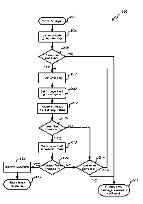
500 proceeds to
block 516 wherein the charging parameter is compared to a threshold value. In
some
17
CA 02910994 201.5-10-29
WO 2014/179813 PCT/US2014/036853
embodiments, this comparison of the charging parameter to the threshold value
can be used to
determine whether to adjust a property of the field, whether to change the
rate of charging of the
energy storage device 308, whether to stop the charging of the energy storage
device 308, and/or
the like. In some embodiments, for example, the threshold can be a temperature
threshold,
wherein a temperature above the threshold value is indicative of and/or can
trigger a request to
decrease the strength of the charge field, a rate of charge threshold, wherein
the rated charge
threshold is specified by some portion of the maximal and/or maximum charge
rate of the pulse
generator 102, 104, a charge state threshold, wherein the charge state
threshold indicates the
charge state of the energy storage device 308 of the pulse generator 102, 104,
a charge voltage
threshold, a strength of charge field threshold, an amount of excess charge
current threshold, or
the like.
[0065] After the charging parameter has been compared to a threshold, the
process 500
proceeds to decision state 518 wherein it is determined if the charging is
complete. In some
embodiments, for example, the completeness of the charging can be determined
based on the
comparison of the charging parameter to one of the thresholds such as, for
example, a
temperature threshold, a charge state threshold, or the like.
[0066] If it is determined that the charging is complete, then the process 500
proceeds to block
520 wherein the completed charging is communicated. In some embodiments, the
communication to complete a charging can include the generation of a message
including
information identifying the completed state of the charging by a processor of
the pulse generator
102, 104, and/or indicating the charge state of the energy storage device 308
of the pulse
generator 102, 104. Thus, in some embodiments, the communication can comprise
a command to
stop charging and/or a request to stop charging, and in some embodiments, the
communication
can comprise information that can be used by the charger 116 to determine
whether to stop
charging of the pulse generator 102, 104. In embodiments in which the
communication
comprises data that can be used by the charger 116 to determine whether to
stop charging of the
pulse generator 102, 104, the process 600 can generate the communication
directly after
determining the charging parameter in block 514. The communication can be sent
from a pulse
generator to the charger 116 via, for example, the network interface 300 of
the pulse generator
102, 104.
18
CA 02910994 201.5-10-29
WO 2014/179813 PCT/US2014/036853
[0067] Returning again to decision state 518, if it is determined that
charging is not complete,
then the process 500 proceeds to decision state 522 wherein it is determined
if an adjustment of
the charge field is desired and/or indicated. In some embodiments, this can
include, determining
if the result of the comparison of a charging parameter to one of the
thresholds indicates that the
charging field and/or the strength of the charging field should be either
increased or decreased. In
one embodiment, for example, the comparison of a charging parameter relating
to the rate of
charge of the pulse generator 102, 104 may indicate a rate of charge that is
lower than a rate of
charge threshold. In one such embodiment, the pulse generator 102, 104 may
request an increase
in the strength of the charging field. Similarly, in one embodiment, the
comparison of a rate of
charge charging parameter relating to the rate of charge with the threshold
for the rated charge
may indicate that the charging rate of the pulse generator 102, 104 is
exceeding a threshold value
In one such embodiments, it may be determined that the strength of the
charging field should be
decreased. Similarly, in some embodiments, a temperature exceeding a threshold
value may be
an indicator of a need to decrease the charging field, a comparison of a
charging parameter
indicating the charge state with the charge state threshold may indicate the
need to decrease the
strength of the charging field, or the like. If it is determined that the
charging field does not need
to be adjusted, then the process returns to block 514 and continues as
outlined above.
[0068] If it is determined that the charging field should be adjusted, then
the process 500
proceeds to block 524 wherein an adjustment request is communicated. In some
embodiments,
the communication adjustment request can include the creation of a message
requesting the
adjustment of the strength of the charging field, and in some embodiments, the
message can
comprise data, including one or several charging parameters determined in
block 514 that can be
used by the charger 116 to determine whether and how to adjust the charge
field.
100691 in some embodiments, the charging message may simply indicate whether
to increment
or decrement the strength of the charging field, and in some embodiments, the
adjustment
message may indicate a degree to which the strength of the charging field
should be increased Or
decreased. In embodiments in which the message comprises data, including one
or several
charging parameters determined in block 514 that can be used by the charger
116 to determine
whether and how to adjust the charge field, the process 600 can generate the
message directly
after determining the charging parameters in block 514, In some embodiments,
the adjustment
19
CA 02910994 201.5-10-29
WO 2014/179813 PCT/US2014/036853
request can be communicated to the charger 116 from the pulse generator 102,
104 via the
network interface 300. After the adjustment request has been communicated, or
returning again
to decision state 522, if it is determined that the charging field should not
be adjusted, the
process 500 returns to block 514 and continues as outlined above.
.. [0070] In one exemplary embodiment, the process 500 can be implemented as
follows, the
pulse generator 102, 104 can generate one or several pulses to stimulate a
nerve and/or portion of
the patient's body. While generating the one or several pulses, the pulse
generator 102, 104 can
receive an identification request and/or a charging request. In some
embodiments, the pulse
generator 102, 104 can retrieve information relating to the charge state of
the energy storage
.. device 308, and determine whether charging is desired and/or advisable. If
charging is desired
and/or advisable, the pulse generator 102, 104 can retrieve identification
information from, for
example, the data module 302 of the pulse generator 102, 104. This information
can identify the
pulse generator 102, 104.
[0071] After the pulse generator 102, 104 has received the identification
request, the pulse
generator 102, 104 can generate a message including information identifying
the pulse generator
102, 104 and, in some embodiments, also including information relating to the
pulse generator
102, 104. In some embodiments, this infot illation relating to the pulse
generdtut 102, 104 can
include information relating to the charge state of the energy storage device
308, to acceptable
rates of charge of the pulse generator 102, 104, and/or the like. This
information relating to the
pulse generator 102, 104 and identifying the pulse generator 102, 104 can be
communicated to
the charger 116 via, for example, the network interface 300.
[0072] After the identification information has been communicated to the
charger 116, the
pulse generator 102, 104 can, according to one or several protocols stored on
pulse generator
102, 104, or according to a request received from the charger 116, determine a
field property at a
first time. In some embodiments, the field property can include a strength of
a charge field which
can, for example, be at a first level that can be, for example, zero and/or
close to zero. In some
embodiments, a zero charge field can comprise a field having a strength of
less than 1 percent of
the maximum charge strength, less than 5 percent of the maximum charge
strength, less than 10
percent of the maximum charge strength, and/or any other or intermediate
value. After the field
CA 02910994 201.5-10-29
WO 2014/179813 PCT/US2014/036853
property has been determined, the pulse generator 102, 104 can communicate the
field property
to the charger 116.
[0073] In some embodiments, after communicating the field property to the
charger, the pulse
generator 102, 104 can determine a second field property at a second time. In
some
embodiments, the second field property can be determined in response to
request received from
the charger 116 requesting information relating to a second field property at
the second time, and
in some embodiments, the second field property can be determined at the second
time according
to one or several protocols of the pulse generator 102, 104.
[0074] In some embodiments, after the second field property has been
determined at the
second time, the pulse generator 102, 104 can communicate the field property
to the charger 116,
and a signal initiating charging can be received and/or charging can be
initiated. In some
embodiments, one or several properties of the charge field and/or of the pulse
generator 102, 104
can be monitored during the charging, and these properties can be compared to
one or several
thresholds to determine when to terminate charging, and/or whether to adjust
the strength of the
charge field. If it is determined to terminate charging, then a message
indicating the completion
of the charging is generated and sent. Similarly, if it is decided to adjust
the strength of the
charge field, then a message requesting an adjustment of the strength of the
charge field is
generated and sent.
[00751 With reference now to Figure 6, a flowchart illustrating one embodiment
of a process
600 for controlling charging of the pulse generator 102, 104 is shown. The
process 600 can be
performed by and/or on charger 116. In some embodiments, the charger 116 can
be, for example,
in communication with the pulse generator 102, 104. The process 600 can begin
a block 602,
wherein the charger 116 is powered. In some embodiments, the powering of the
charger 116 can
occur when the charger 116 is turned on.
100761 After the charger 116 is powered, the process 600 proceeds to block
604, wherein a
query message is communicated. In some embodiments, the query message can
comprise the
identification request, and can include a request for identification of any
pulse generators 102,
104 receiving the query message. In some embodiments, the query message can be
generated by
21
CA 02910994 201.5-10-29
WO 2014/179813 PCT/US2014/036853
the charger 116 and can be communicated to one or several pulse generators
102, 104 via the
network interface 400.
[0077] After the query message has been communicated, the process 600 proceeds
to decision
state 606, wherein it is determined if a response to the query message has
been received. In some
embodiments, the response can be the identification communication from block
504 of Figure 5.
In some embodiments, this determination can be made after a period such as,
for example, 0.5
seconds, 1 second, 2 seconds, 5 seconds, and/or any other or intermediate
length of time. If it is
determined that no response has been received, then the process 600 proceeds
to block 616
wherein an error is triggered and an error message is provided to the user. In
some embodiments,
the error message can indicate that no pulse generator 102, 104 was found, and
the error message
can be displayed to the user.
[0078] Returning again to decision state 606, if it is determined that a
response was received,
then the process 600 proceeds to block 607 wherein the charging frequency of
the charger 116 is
tuned by actively adjusting the tuning frequency of the charger 116, and
specifically of the
features of the charging module 404. In some embodiments, this tuning can
result in the
components of the charging module 404 operating at a frequency substantially
equal to the
resonant frequency of, for example, the features of the charging -module 306
of the pulse
generators 102, 104. This tuning can include measuring the output power of the
charging module
404 and reporting the output power to the processor of the charger 116. The
actual power
delivered to the charging module 306 of the pulse generator 102, 104 can be
measured and
reported to the charger 116. Based on the actual power delivered to the
charging module 306 of
the pulse generator 102, 104 and the output power of the charging module 404
of the charger
116, the charger 116 may adjust the tuning frequency of the charging module
404 if the actual
power delivered to the receiving coil is not at a desired level. This may be
repeated until the
charger determines that the actual power delivered to the charging module 306
of the pulse
generator is at a desired level. In some embodiments, the tuning of block 607
can be performed
before charging starts, at instance during charging, and/or continuously
during charging. In some
embodiments, the tuning of block 607 may be omitted from process 600.
[00791 The process 600 proceeds to block 608, wherein the charge field is set
to first power
and/or strength. In some embodiments, the charge field can be sent to a low
first power and/or
22
CA 02910994 201.5-10-29
WO 2014/179813 PCT/US2014/036853
strength. In some embodiments, the low first power and/or strength can be used
to identify
whether one or several other charge fields can affect the charging of the
pulse generator 102,
104. In some embodiments, the low first power can comprise a power that is 0%
of the
maximum charge field strength and/or power, 1% of the maximum charge field
strength and/or
.. power, 2% of the maximum charge field strength and/or power, 5% of the
maximum charge field
strength and/or power, 10% of the maximum charge field strength and/or power,
20% of the
maximum charge field strength and/or power, and/or any other or intamediate
percent of the
maximum charge field strength and/or power.
100801 After the charge field has been set to the first strength and/or power,
the process 600
proceeds to block 610 wherein charge field strength data is received. In some
embodiments, the
charge field strength data can identify the strength of the charge field at
the pulse generator 102,
104. In some embodiments, the charge field strength can be detected with
components of the
pulse generator 102, 104 including, for example, components of the charging
module 306. The
charge field strength data can be received at the charger 116 via the network
interface 400 of the
charger 116.
[00811 After the charge field strength data has been received, the process 600
proceeds to
decision state 612 wherein it is determined if the charge field strength data
indicates a detected
charge field that is less than a threshold. In some embodiments, this
comparison can identify
whether electric fields from sources other than the charger 116 are detectable
by the pulse
generator 102, 104. In some embodiments, this comparison of the detected
charge field strength
to the charge field threshold can also provide an indication as to the degree
to which the charger
116 can control the charging of the pulse generator 102, 104 or to which the
pulse generator 102,
104 is within charging range of the charger 116. In some embodiments, the
threshold can
identify a value corresponding to a detected charge strength that can be, for
example, greater
than 50% of the first charge field power level, greater than 75% of the first
charge field power
level, greater than 90% of the first charge field power level, greater than
100% of the first charge
field power level, greater than 110% of the first charge field power level,
greater than 120% of
the first charge field power level, greater than 150% of the first charge
field power level, greater
than 150% first charge field power level, greater than 200% of the first
charge field power level,
greater than 500% of the first charge field power level, greater than 1000% of
the first charge
23
CA 02910994 201.5-10-29
WO 2014/179813 PCT/US2014/036853
field power level, greater than 10,000% of the first charge field power level,
and/or any other or
intermediate percent of the first charge field power level. If it is
determined that the detected
strength of the charge field is greater than the threshold, then the process
proceeds to decision
state 614 wherein it is determined if there is an additional pulse generator
102, 104. In some
embodiments, this determination can include determining whether more than one
response was
received following the query message. If it is determined that there is an
additional pulse
generator 102, 104, then the process 600 returns to block 608 and proceeds as
outlined above. if
it is determined that there is no additional pulse generator 102, 104, then
the process 600
proceeds to block 616 wherein an error is triggered and an error message is
provided to the user.
In some embodiments, the error message can indicate that no pulse generator
102, 104 was
found, and the error message can be displayed to the user.
10082] Returning again to decision state 612, if it is determined that the
detected charge field
strength and/or power is less than the threshold, then the process 600
proceeds to block 618
wherein the charge field is set to a second charge power. In some embodiments,
setting the
charge field to a second charge power and/or strength can include changing the
strength of the
charge power from a first non-zero strength to a second, increased strength,
which strength can
be, for example, the maximum charge field strength, and in some embodiments,
can include
changing the strength from a first zero strength to a second, increased
strength, which strength
can be, for example, the maximum charge field strength. In some embodiments,
the charge field
can be set to a high second charge power such as, for example, 75 /0 of the
maximum strength of
the charge field power, 80% of the maximum strength the charge field power,
90% of the
maximum strength of the charge field power, 100% of the maximum strength of
the charge field
power, and the/or any other intermediate percent of the maximum charge field
value.
Advantageously, setting the charge field at a second charge strength and/or
power can be used to
determine the proximity of the pulse generator 102, 104 to the charger 116.
10083] In some embodiments, setting the charge field to a second power can
further include
receiving charge field strength data identifying a detected power of the
charge field after the
charge field has been set to the second charge field power.
[0084] After the charge field presence is set to the second power, the process
600 proceeds to
decision state 620 wherein it is determined if the power and/or strength of
the charge field as
24
CA 02910994 201.5-10-29
WO 2014/179813 PCT/US2014/036853
detected by the pulse generator 102, 104 is greater than a threshold. In some
embodiments, this
comparison can indicate if an adequate amount of the electrical field is
detectable at the pulse
generator 102, 104 to allow charging of the pulse generator 102, 104 at a
desired rate, In some
embodiments, the threshold can identify a percentage of the second charge
field power level such
as, for example, 60% of the second charge field power level, 70% of the second
charge field
power level, 70% of the second charge field power level, 80% of the second
charge field power
level, 90% of the second charge field power level, 100% of the second charge
field power level,
110% of the second charge field power level, 120% of the second charge field
power level,
150% of the second charge field power level, and/or any other or intermediate
percent of the
second charge field power level. In some embodiments, the comparison of the
detected strength
of the charge field to the second charge field power level via comparison to
the threshold can
include normalizing of the detected strength of the charge field based on the
strength of the
charge field detected in block 610. In some embodiments, this normalization
can minimize any
data skew that may be caused by electric fields from sources other than the
charger 116. If it is
determined that the detected strength of the charge field is less than the
threshold, then the
process 600 proceeds to decision state 614 and proceeds as outlined above.
[0085] If it is determined that the detected strength of the charge field is
greater than the
threshold, then the process 600 proceeds to block 622 and the pulse generator
102, 104 is
identified. In some embodiments, this can include storing identification
information of the
identified pulse generator 102, 104 such as, for example, storing the serial
number of the
identified pulse generator.
[0086] After pulse generator 102, 104 has been identified, the process 600
proceeds to block
624 wherein charge monitoring is started. In some embodiments, the starting of
charge
monitoring can include the initiation of charging of the pulse generator 102,
104. In some
embodiments, initiation of charging of the pulse generator 102, 104 can
include setting the
charge field to a third charge field strength. In some embodiments, this third
charge field strength
can be identified based on information associated with the pulse generator
102, 104 including,
for example, the energy storage capacity of the energy storage device 308, the
charge state of the
energy storage device 308, the maximum rate of charge of the pulse generator
102, 104, one or
several field properties determined by the pulse generator 102, 104 including,
for example, the
CA 02910994 201.5-10-29
WO 2014/179813 PCT/US2014/036853
strength of the charge field at the first time and/or the strength of the
charge field at the second
time, and/or the like. In some embodiments, this information can be received
from the pulse
generator 102, 104 as part of block 504 of process 500, and in some
embodiments, this
information can be retrieved from the data module 402 of the charger 116. In
some embodiments
in which a plurality of pulse generators 102, 104 have been detected, the
third charge field
strength can be set to be detectable by one or several of the plurality of
pulse generators 102, 104
and to be undetectable by one or several of the plurality of pulse generators
102, 104. After the
third charge field strength has been identified, in some embodiments, the
charger 116 can
generate and send a message to the pulse generator 102, 104 indicating the
initiation of charging.
Further details of charge monitoring will be discussed with respect to Figure
7 below.
100871 With reference now to Figure 7, a flowchart illustrating one embodiment
of a process
700 for charge monitoring is shown. In some embodiments, the process 700 can
be performed to
monitor and/or to control the charging. In some embodiments, this can result
in improved
charging efficiency and decreased risk of injury and/or discomfort created by
the charging of the
pulse generator 102, 104.
[0088] The process 700 continues from block 624 of Figure 6 and proceeds to
block 704,
whetein the charge message is received. In some embodiments, the charge
message can be
received in response to a request send by the charger 116, and in some
embodiments, the charge
message can be received by the operation of pulse generator 102, 104 according
to one or several
stored protocols. In some embodiments, the charge message can include one or
both of the
communication indicating completed charging or communication requesting an
adjustment in the
charge strength. In some embodiments, and as discussed with respect to block
520 and 524 of
Figure 5, these messages can include one or both of a command or request for
the charger 116 to
take an action, and/or data that can be used by the charger 116 to determine
whether to take an
action such as, for example, stopping charging and/or adjusting the charge
field strength. The
charge message can be received by the network interface 400 of the charger
116.
[0089] After the charge message has been received, the process 700 proceeds to
decision state
706, wherein it is determined if charging is complete. In some embodiments,
this determination
can include determining whether the charge message included a command/request
to stop
charging and/or whether the charge message included data indicative of
completeness of
26
CA 02910994 201.5-10-29
WO 2014/179813 PCT/US2014/036853
charging. In some embodiments, the completeness of charging based on data
received in the
charge message can be determined by comparing the received data to one or
several thresholds in
the same manner as outlined in process 500 of Figure 5.
[0090] If it is determined that charging is complete, then the process 700
proceeds to block 708
wherein the charge field is turned off. In some embodiments, this can include
storing data
relating to the completed charging such as, for example, the identification of
the charged pulse
generator, the amount of charge provided to the pulse generator, the internal
resistance of the
energy storage device of the pulse generator 102, 104, the duration of the
charging event, or the
like. In some embodiments, this information can be used to estimate the life
of the pulse
generator 102, 104 and/or the energy storage device 308 of the pulse generator
102, 104. This
data can be stored in the memory of the charger 116 and/or transmitted to one
or both of the
clinician programmer 118 and the patient remote 120.
[0091] Returning again to decision state 706, if it is determined that
charging is not complete,
the remaining charge time can be estimated. In some embodiments, this estimate
can be based on
.. previous data collected relating to the charging of one or several pulse
generators 102, 104,
based on data received in the charge message including, for example, the
charge state of the
energy storage device 308, or the like. In some embodiments, this estimate can
be generated by
the charger 116 and/or received from the pulse generator 102, 104 as part of
the charge message.
[0092] After the remaining charge time has been estimated, the process 700
proceeds to
decision state 712 wherein it is determined whether to adjust the charge field
strength. This
determination can be based on the charge message, including information in the
charge message
and/or on the estimated remaining charge time. In some embodiments, this
decision can include
identifying whether the charge message included a command or request to adjust
the strength of
the charge field and/or determining whether information contained in charge
message correlates
with criteria for adjusting the strength of the charge message. In some
embodiments, the
correlation between information contained in the charge message and adjusting
the strength of
the charge message can be determined according to steps outlined with respect
to process 500,
and specifically according to block 516 and decision state 522, which steps
can be performed, in
some embodiments, by the charger 116.
27
CA 02910994 201.5-10-29
WO 2014/179813 PCT/US2014/036853
[0093] If it is determined that the charge field strength should be adjusted,
then the process 700
proceeds to block 714 wherein the field strength is adjusted. In some
embodiments the
adjustment of the charge field strength can include storing data relating to
the adjustment and/or
the circumstances leading to the adjustment. In some embodiments, this data
can include the
amount of charge provided until the adjustment, the amount of charge time
until the adjustment,
or the like. In some embodiments, this information can be used to estimate the
life of the pulse
generator 102, 104 and/or the energy storage device 308 of the pulse generator
102, 104. This
data can be stored in the memory of the charger 116 and/or transmitted to one
or both of the
clinician programmer 118 and the patient remote 120.
[0094] After the charge field strength has been adjusted, or returning again
to decision state
712, if it is determined that no adjustment to the charge field strength is
needed, then the process
700 proceeds to block 716 and waits until a predetermined amount of time has
passed. In some
embodiments, the predetermined time can comprise a percent of the estimated
remaining charge
time. Advantageously, by waiting a percent of the estimated remaining charge
time, the
likelihood of overcharging is decreased. In some embodiments, the
predetermined time can
comprise, for example, 25 percent of the estimated remaining charge time, 50
percent of the
estimated remaining charge time, 75 percent of the estimated remaining charge
time, 80 percent
of the estimated remaining charge time, 90 percent of the estimated remaining
charge time, 95
percent of the estimated remaining charge time, 98 percent of the estimated
remaining charge
time, 99 percent of the estimated remaining charge time, and/or any other or
intermediate percent
of the remaining charge time. In some embodiments, this predetermined amount
of time can be
calculated by determining an estimated amount of time for the pulse generator
102, 104 to reach
a predetermined charge state that is a percent of a fully charged charge
state. In some
embodiments, this percent can be a 70 percent charge state, an 80 percent
charge state, a 90
percent charge state, a 95 percent charge state, a 98 percent charge state, a
99 percent charge
state, and/or any other or intermediate percent charge state. After the
process 700 has waited for
the predetermined amount of time, the process 700 returns to block 704 and
proceeds as outlined
above.
100951 In the foregoing specification, the invention is described with
reference to specific
embodiments thereof, but those skilled in the art will recognize that the
invention is not limited
28
CA 02910994 201.5-10-29
WO 2014/179813 PCT/US2014/036853
thereto. Various features and aspects of the above-described invention can be
used individually
or jointly. Further, the invention can be utilized in any number of
environments and applications
beyond those described herein without departing from the broader spirit and
scope of the
specification. The specification and drawings are, accordingly, to be regarded
as illustrative
rather than restrictive. It will be recognized that the terms "comprising,"
"including," and
"having," as used herein, are specifically intended to be read as open-ended
terms of art.
29