Language selection

Search

Patent 2911074 Summary

Third-party information liability

Some of the information on this Web page has been provided by external sources. The Government of Canada is not responsible for the accuracy, reliability or currency of the information supplied by external sources. Users wishing to rely upon this information should consult directly with the source of the information. Content provided by external sources is not subject to official languages, privacy and accessibility requirements.

Claims and Abstract availability

Any discrepancies in the text and image of the Claims and Abstract are due to differing posting times. Text of the Claims and Abstract are posted:

  • At the time the application is open to public inspection;
  • At the time of issue of the patent (grant).
(12) Patent Application: (11) CA 2911074
(54) English Title: PADLOCK PROTECTOR
(54) French Title: DISPOSITIF DE PROTECTION DE CADENAS
Status: Deemed Abandoned and Beyond the Period of Reinstatement - Pending Response to Notice of Disregarded Communication
Bibliographic Data
(51) International Patent Classification (IPC):
  • E05B 67/38 (2006.01)
  • E05B 67/06 (2006.01)
(72) Inventors :
  • KYLLONEN, VELI-PEKKA (Finland)
  • VIITANEN, VEIKKO (Finland)
  • HEDMAN, TONI (Finland)
(73) Owners :
  • ABLOY OY
(71) Applicants :
  • ABLOY OY (Finland)
(74) Agent: KIRBY EADES GALE BAKER
(74) Associate agent:
(45) Issued:
(86) PCT Filing Date: 2014-06-18
(87) Open to Public Inspection: 2014-12-31
Examination requested: 2019-05-24
Availability of licence: N/A
Dedicated to the Public: N/A
(25) Language of filing: English

Patent Cooperation Treaty (PCT): Yes
(86) PCT Filing Number: PCT/FI2014/050484
(87) International Publication Number: WO 2014207302
(85) National Entry: 2015-10-30

(30) Application Priority Data:
Application No. Country/Territory Date
20135715 (Finland) 2013-06-28

Abstracts

English Abstract

The invention relates to a padlock protector comprising a shackle protector. The shackle protector is composed from two parts. The parts are to be placed to the opposite sides of the shackle, and they are formed into the shape of the loop and surface of the shackle. The side edges of the parts are jigsaw puzzle edges in their shape.


French Abstract

L'invention concerne un dispositif de protection de cadenas qui comprend un dispositif de protection d'anse. Le dispositif de protection d'anse est composé de deux parties. Les parties doivent être placées sur les côtés opposés de l'anse, et présentent la forme de la boucle et de la surface de l'anse. Les bords latéraux des parties présentent des formes de bords de pièces de puzzle.

Claims

Note: Claims are shown in the official language in which they were submitted.

5
Claims
1. A padlock protector comprising a shackle protector, characterized in that
the
shackle protector is composed from two parts (1A, 1B), which are to be placed
to the
opposite sides of the shackle (2), and which parts are formed into the shape
of the
loop and surface (2A) of the shackle, and which side edges (4A, 4B, 40, 4D) of
the
parts are jigsaw puzzle edges in their shape.
2. A padlock protector according to claim 1, characterized in that the end
edges
(5A, 5B, 5C, 5D) of the parts are even.
3. A padlock protector according to claim 2, characterized in that the outer
surfac-
es (40) of the parts (1A, 1B) are curved.
4. A padlock protector according to claim 3, characterized in that the parts
(1A,
1B) are of a flexible material.
S. A padlock protector according to claim 4, characterized in that it
comprises a
protective case (6) having solid sides (6A) and an open bottom (60), and which
case
has a top side (6B) with a hole (7).
6. A padlock protector according to claim 5, characterized in that hole (7) of
the
top side is fitted such that the shackle (2) fits through the hole.

Description

Note: Descriptions are shown in the official language in which they were submitted.


CA 02911074 2015-10-30
WO 2014/207302 PCT/F12014/050484
1
Padlock protector
Technical field
The invention relates to a padlock protector.
Prior art
It is known that a padlock and also its shackle can be protected with a
separate
case and shackle protector. WO 8707669 discloses a known padlock protector. US
4226100 discloses another known padlock protector. The purpose of these
protectors
is to protect the padlock from water. Additionally, the protectors dampen the
noise,
which can be created if the padlock rattles against the object to be locked,
such as a
door. In both publications, the shackle can be protected with a rubber hose,
which is
threaded around the shackle.
Therefore, known solutions efficiently protect the padlock from water and
other
outside factors, such as dust. Padlock protectors are, however, difficult to
place onto
the padlock.
Brief description of the invention
The object of the invention is to obviate the disadvantages of known art. The
ob-
ject is achieved in the manner described in the dependant claim. The
independent
claims describe various embodiments of the invention.
The invention is based on the idea that the padlock itself withstands outside
condi-
tions quite well, wherein a padlock protector does not need to be, for
example, water-
proof. The protector can be formed for the purpose of a partial protection. A
padlock
protector according to the invention protects the shackle of the padlock such
that it is
not free to come into direct contact with its corresponding parts to be
locked. In this
way, corrosion of the shackle is very effectively prevented.

CA 02911074 2015-10-30
WO 2014/207302 PCT/F12014/050484
2
A padlock protector according to the invention comprises a shackle, protector
which is composed from two parts. The parts are to be placed to the opposite
sides of
the shackle, and they are formed into the shape of the loop and surface of the
shack-
le. The side edges of the parts are formed like the edges of a jigsaw puzzle.
The jig-
saw puzzle edges of the parts are arranged to fit against each other.
List of figures
In the following, the invention is described in more detail by means of the
accom-
panying figures, in which
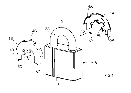
Fig. 1 shows an example of a padlock protector according to the
invention,
Fig. 2 shows the example of Fig. 1 as installed on the padlock,
Fig. 3 shows another example of a padlock protector according to the
in-
vention, and
Fig. 4 shows the example of Fig. 3 as installed on the padlock.
Description of the invention
Fig. 1 shows an example of a padlock protector according to the invention. The
padlock protector comprises a shackle protector composed from two parts 1A,
1B.
The parts are to be placed to the opposite sides of the shackle 2. The parts
are
formed into the shape of the loop and surface of the shackle 2A. The shackle
is a U-
shaped loop in shape, which together with the body 3 of the padlock 8 forms a
closed
loop. As can be seen from the figure, the side edges 4A, 4B, 40, 4D of the
parts are
jigsaw puzzle edges in their shape.
The jigsaw puzzle edges of the parts 1A, 1B fit against each other.
Additionally, the
parts are manufactured from a suitably flexible material, such as from a
plastic suita-
ble for the purpose. When the parts are placed from the opposite sides of the
shackle
2 against each other, the jigsaw puzzle edges 4A, 4B, 40, 4D flex such that
the parts
settle against the surface 2A of the shackle and the edges go against each
other. The
outer surfaces 40 of the parts are therefore curved, and they curve according
to the

CA 02911074 2015-10-30
WO 2014/207302 PCT/F12014/050484
3
surface 2A of the shackle. The parts cover the surface of the shackle of the
padlock 8
in the locking position, wherein the shackle 2 is not free to come into direct
contact
with its corresponding part(s) to be locked. Arrows Al and A2 show, how the
parts of
the shackle protector are placed onto the shackle. Fig. 2 shows, how the parts
1A, 1B
of the shackle protector cover the shackle. The jigsaw puzzle edges 4A, 4B,
40, 4D
fit against each other, wherein the parts 1A, 1B on the opposite sides of the
shackle 2
are connected to each other via the jigsaw puzzle edges.
The doors of many storages and properties are provided with metal loops or
metal
plates having holes for the shackle of a padlock, so that they can be locked
with a
padlock. The metal plates and metal loops are often made from stainless steel,
wherein the shackle of the padlock begins to rust due to electrochemical
corrosion.
The shackle of the padlock is generally of hardened steel, which can also be
chrome-
plated. If the chrome is worn or has been broken, then the shackle is readily
suscep-
tible to corrosion.
Fig. 3 shows an example of a padlock protector according to the invention, com-
prising, in addition to the shackle protector 1A, 1B described above, a
protective case
6 having solid sides 6A and an open base 60. The case has a top side 6B with a
hole
7. The case is easy to place onto the padlock 8 by threading it from the side
of the
shackle 2 onto the lock body 3. The arrow A3 shows the placing of the case
onto the
body of the padlock. The hole 7 of the top side 6B is fitted such that the
shackle fits
through the hole. The solid area of the top side 6B settles against the upper
surface
3A of the body of the padlock. The protective case 6 protects the surface of
the body
of the padlock from wear and also largely prevents direct contact of external
parts
with the body 3. Fig. 4 shows, how the padlock is protected with a case 6 and
a
shackle protector 1A, 1B.
Both the shackle protector 1A, 1B and the protective case 6 are manufactured
from a plastic suitable for the purpose, one which flexes suitably. Thus, the
shackle
protector and protective case flex somewhat, and the jigsaw puzzle edges 4A,
4B,
40, 4D of the shackle protector can be placed against the surface 2A of the
shackle.
A suitable plastic also insulates the shackle from above said metal plates or
metal
loops, preventing corrosion conditions from forming. A shackle protector also
protects

CA 02911074 2015-10-30
WO 2014/207302 PCT/F12014/050484
4
the surface of the shackle from wear. Because the shackle 2 itself withstands
water
quite well, thus it does not need to be waterproof. A shackle protector is
fast and easy
to install around a shackle. It can also be refitted to existing padlocks. A
shackle pro-
tector can be symmetrical, i.e. the parts 1A, 1B are similar, as is shown in
the figures.
In this case, the same component fits both sides of the shackle. The parts can
also
be manufactured as different, i.e. asymmetrical. In asymmetrical parts, the
jigsaw
puzzle edges also settle against each other.
As can be observed from the figures, the end edges 5A, 5B, 50, 5D of the parts
are even in the present embodiment. Depending on the shape of the padlock, the
end edges can also be formed to follow the shape of the body of the padlock.
The
end edges 5A, 5B, 50, 5D can therefore be, for example, curved. The jigsaw
puzzle
edges 4A, 4B, 40, 4D can be formed in a different manner, nor do they
therefore
necessarily need to be in the shape shown in the figures. Both parts of the
shackle
protector are formed into a U-shape. Because the shackle 2 (the loop of the
shackle)
can be formed in many various manners, by U-shape is meant, in this
connection,
any shape of the bent shackle, which forms with the padlock a closed loop. The
most
common cross-section of the loop of the shackle is a circle, as it is
advantageous in
relation to manufacture and use. However, it is possible that the cross-
section has
some other shape, wherein the shape of the surface of the loop deviates from
being a
circular surface, and the shackle protector is formed into the corresponding
shape of
the surface. The outer surfaces of the parts of the shackle protector are
therefore
curved. The parts curve onto the shackle.
In light of the examples presented above, it is obvious that an embodiment
accord-
ing to the invention can be provided by many various solutions, not merely by
the ex-
amples presented in this connection. The invention can therefore be
implemented by
various embodiments within the scope of the presented claims.

Representative Drawing
A single figure which represents the drawing illustrating the invention.
Administrative Status

2024-08-01:As part of the Next Generation Patents (NGP) transition, the Canadian Patents Database (CPD) now contains a more detailed Event History, which replicates the Event Log of our new back-office solution.

Please note that "Inactive:" events refers to events no longer in use in our new back-office solution.

For a clearer understanding of the status of the application/patent presented on this page, the site Disclaimer , as well as the definitions for Patent , Event History , Maintenance Fee  and Payment History  should be consulted.

Event History

Description Date
Inactive: Dead - No reply to s.86(2) Rules requisition 2021-10-15
Application Not Reinstated by Deadline 2021-10-15
Letter Sent 2021-06-18
Common Representative Appointed 2020-11-07
Deemed Abandoned - Failure to Respond to an Examiner's Requisition 2020-10-15
Examiner's Report 2020-06-15
Inactive: Report - QC passed 2020-06-09
Common Representative Appointed 2019-10-30
Letter Sent 2019-05-30
Request for Examination Requirements Determined Compliant 2019-05-24
Request for Examination Received 2019-05-24
All Requirements for Examination Determined Compliant 2019-05-24
Change of Address or Method of Correspondence Request Received 2018-01-09
Application Received - PCT 2015-11-06
Inactive: Notice - National entry - No RFE 2015-11-06
Inactive: IPC assigned 2015-11-06
Inactive: First IPC assigned 2015-11-06
National Entry Requirements Determined Compliant 2015-10-30
Application Published (Open to Public Inspection) 2014-12-31

Abandonment History

Abandonment Date Reason Reinstatement Date
2020-10-15

Maintenance Fee

The last payment was received on 2020-05-25

Note : If the full payment has not been received on or before the date indicated, a further fee may be required which may be one of the following

  • the reinstatement fee;
  • the late payment fee; or
  • additional fee to reverse deemed expiry.

Please refer to the CIPO Patent Fees web page to see all current fee amounts.

Fee History

Fee Type Anniversary Year Due Date Paid Date
Basic national fee - standard 2015-10-30
MF (application, 2nd anniv.) - standard 02 2016-06-20 2016-05-26
MF (application, 3rd anniv.) - standard 03 2017-06-19 2017-05-24
MF (application, 4th anniv.) - standard 04 2018-06-18 2018-05-24
MF (application, 5th anniv.) - standard 05 2019-06-18 2019-05-23
Request for examination - standard 2019-05-24
MF (application, 6th anniv.) - standard 06 2020-06-18 2020-05-25
Owners on Record

Note: Records showing the ownership history in alphabetical order.

Current Owners on Record
ABLOY OY
Past Owners on Record
TONI HEDMAN
VEIKKO VIITANEN
VELI-PEKKA KYLLONEN
Past Owners that do not appear in the "Owners on Record" listing will appear in other documentation within the application.
Documents

To view selected files, please enter reCAPTCHA code :


To view images, click a link in the Document Description column. To download the documents, select one or more checkboxes in the first column and then click the "Download Selected in PDF format (Zip Archive)" or the "Download Selected as Single PDF" button.

List of published and non-published patent-specific documents on the CPD .

If you have any difficulty accessing content, you can call the Client Service Centre at 1-866-997-1936 or send them an e-mail at CIPO Client Service Centre.


Document
Description 
Date
(yyyy-mm-dd) 
Number of pages   Size of Image (KB) 
Drawings 2015-10-30 2 31
Claims 2015-10-30 1 25
Abstract 2015-10-30 1 52
Description 2015-10-30 4 179
Representative drawing 2015-10-30 1 8
Cover Page 2016-02-03 1 33
Notice of National Entry 2015-11-06 1 193
Reminder of maintenance fee due 2016-02-22 1 110
Reminder - Request for Examination 2019-02-19 1 115
Acknowledgement of Request for Examination 2019-05-30 1 175
Courtesy - Abandonment Letter (R86(2)) 2020-12-10 1 549
Commissioner's Notice - Maintenance Fee for a Patent Application Not Paid 2021-07-30 1 552
National entry request 2015-10-30 3 79
International search report 2015-10-30 2 58
Request for examination 2019-05-24 2 49
Examiner requisition 2020-06-15 4 168