Note: Descriptions are shown in the official language in which they were submitted.
CA 02911184 2015-11-02
P1096-1CA
1
SUSPENSION ROTARY WATER PRESSURE
ENERGY CONVERSION POWER OUTPUT DEVICE
FIELD OF THE TECHNOLOGY
[I] The present invention relates to a Hydroenergy conversion device of energy
conversion
equipment, and particularly to a suspension rotary water pressure energy
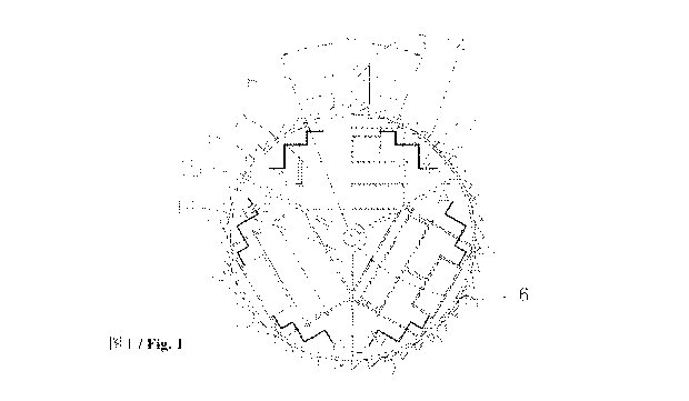
conversion power
output device.
TECHNOLOGY BACKGROUND
[2] Hydroenergy is a renewable and clean energy. Hydroenergy refers to energy
resources
such as kinetic energy, potential energy and pressure energy of a body of
water. Currently,
Hydroenergy applications only make use of kinetic energy and potential energy
of water.
Hydropower is a typical and single use of kinetic energy and potential energy
of water to
generate power. Hydropower has the problems of difficulty in construction,
high installation
cost, low controllability, and low efficiency in power generation. As a clean
and renewable
energy, in addition to kinetic energy and potential energy, hydroenergy in
fact possesses
enormous pressure energy. This pressure energy can be utilized to
significantly improve
hydroenergy operation efficiency and to serve the humanity. In today's
increasing shortage of
energy, we can take full advantage of the development of conversion of water
pressure
energy to hydraulic energy, or use the pressure energy to generate
electricity. It is cost
effective and has far-reaching social significance.
CA 02911184 2015-11-02
P1096-1CA
2
[3] Chinese Patent CN200820089479.0 provided a float-type power-generating
device. The
main structure is characterized by having at least two or more single set of
power-generating
device. Each single set of power-generating device includes water tank, float,
piston, and
hydraulic cylinder. The float is placed in the water tank formed with a water
inlet and a water
outlet. The float is connected with the piston through a connecting rod. The
piston is provided
inside the hydraulic cylinder. The body of the hydraulic cylinder is fixed to
the water tank by
a fixing frame. The hydraulic cylinder is connected with a generator via a
hydraulic pump.
An oil tank is provided on an oil return passage between the hydraulic
cylinder and the
hydraulic pump. A one-way valve is provided on an oil passage between the
hydraulic
cylinder and the oil tank. Another one-way valve is provided on an oil passage
between the
hydraulic pump and the oil tank. Although the structure of the device is
simple, it is not
suitable for industrial production of electricity. Since water flow must have
to be ensured
during production process, it limits the geographical environment usage of the
invention.
Also, in each process of water filling and water draining, the generated
hydraulic energy is
not continuous, and therefore it exists the shortcomings of poor operability
and
controllability.
DISCLOSURE OF THE INVENTION
[4] The technical problem to be solved is to provide a high efficient power
output device
which is simple in structure, easy to operate, low in friction and wearing,
higher in energy
conversion efficiency, more stable and reliable, and able to make better use
of various forms
of water energy, especially water pressure energy that can be converted into
industrial
hydraulic power.
CA 02911184 2015-11-02
P1096-1CA
3
[5] The present invention can solve the above-mentioned existing technical
problems through
the implementation of the below technical solutions.
[6] The present invention includes a supporting base, a rotating shaft, energy
converters, and
a hydraulic transmission mechanism, characterizing in that at least three
energy converters 2
are radially and uniformly provided inside a ring-shaped frame 1 which is
concentric with the
rotating shaft 6 provided on the supporting base 4. The ring-shaped frame 1 is
driven to rotate
by a turnover mechanism3. The transmission mechanism includes a hydraulic
cylinder 19,
one-way valves 24, 25, oil pipes 26, 27, a hydraulic oil tank 11, a high-
pressure oil
accumulator 12 and a hydraulic actuator 5.
[7] To achieve a better operating effect, the following technical solutions
can also be
implemented.
[8] The rotating shaft 6 has a hollow center. A high-pressure oil inlet pipe
28 connecting with
oil inlets A passes through a hollow portion at one end of the rotating shaft
6 and connects
with a hydraulic oil tank 11 through a rotary joint 9, and a high-pressure oil
outlet pipe 29
connecting with oil outlets B passes through a hollow portion at the other end
of the rotating
shaft 6 and connects with a high-pressure oil accumulator 12 through a second
rotary joint 10.
The number of the energy converters 2 can be an odd number greater than three.
An oil pipe
27 at the oil outlet B of each energy converter 2 is provided with a hydraulic
valve 7, and a
hydraulic valve control device 8 is provided on an upper part of the ring-
shaped frame I. The
hydraulic valve 7 can be a magnetically-controlled hydraulic valve, and the
hydraulic valve
control device 8 can be a magnetically-controlled hydraulic valve control
device. The
hydraulic valve 7 can be a mechanically-controlled hydraulic valve, and the
hydraulic valve
control device 8 can also be a mechanically-controlled hydraulic valve control
device. The
hydraulic valve control device 8 is disposed at an angle of 5 --- 20 with
respect to a vertical
axis of the ring-shaped frame 1. The turnover mechanism 3 includes a ring-
shaped driving
CA 02911184 2015-11-02
P1096-1CA
4
gear 14 provided on an outer side of the ring-shaped frame 1, and a driving
motor 13 with a
mating gear which is provided at an outer portion of the ring-shaped driving
gear 14 and
engageable therewith. The driving motor 13 with the mating gear is a passively-
operating
power-generating electric motor. The turnover mechanism 3 includes a ring-
shaped blade set
15 provided on an outer side of the ring-shaped frame 1. The rotating shaft 6,
the ring-shaped
frame 1 or the energy converters 2 is provided with a counterweight 16 to
counteract the
buoyancy of the floating buoy. This renders the entire device, including the
counterweight 16,
the rotating shaft 6, the ring-shaped frame 1 and the energy converters 2, to
be in a
microgravity suspension state in water.
[9] The present invention uses counterweight to make the entire device, except
for the
supporting base 4, to be in microgravity suspension state in water. With the
aid of small
kinetic energy, potential energy, or smaller external force of water, the
entire device can be
rotated. Also, the entire device can be rotated by a driving motor so as to
result in the energy
converters being turned upside down. During rotation process, floating buoys
release pressure
energy of water to realize the conversion of hydraulic energy. Multiple set of
devices can be
combined in order to continuously press hydraulic oil into a high-pressure oil
accumulator for
direct use, or for use in hydraulic power generation etc.
BRIEF DESCRIPTION OF THE DRAWINGS
[10] Fig. 1 is a left side half-sectional view of the first embodiment of the
present invention;
[11] Fig. 2 is an illustrative diagram of the structure of the first
embodiment of the present
invention;
[12] Fig. 3 is an illustrative diagram of the structure of an energy converter
of the first
embodiment of the present invention;
CA 02911184 2015-11-02
P1096-1CA
[13] Fig. 4 is a left side half-sectional view of the second embodiment of the
present
invention; and
[14] Fig. 5 is an illustrative diagram of the structure of an energy converter
of the second
embodiment of the present invention.
BEST EMBODIMENTS EMBODYING THE INVENTION
[15] The present invention will be described by way of the following
accompanying
embodiments.
[16] Embodiment 1
[17] The device of the present invention includes energy converters 2 fixedly
connected with
a rotating shaft 6, a ring-shaped frame 1 coaxial and fixedly connected with
the rotating shaft
6, a turnover mechanism 3, a supporting base 4, and a hydraulic transmission
mechanism.
The transmission mechanism includes a hydraulic cylinder 19, one-way valves
24, 25, oil
pipes 26, 27, a hydraulic oil tank 11, a high-pressure oil accumulator 12 and
a hydraulic
actuator 5.
[18] The energy converter 2 includes a floating buoy 22, upper and lower base
plates 17, 18,
the hydraulic cylinder 19, and a piston 20. The upper and lower base plates
17, 18 are fixedly
connected together by at least two fixation rods 21. The hydraulic cylinder 19
is mounted on
the upper base plate 17. An upper end of the floating buoy 22 is provided with
a connecting
rod 23, which is connected with the piston 20 of the hydraulic cylinder 19.
The floating buoy
22 and the fixation rods 21 are movably connected by linear bearings. The
floating buoy 22
can slide along the fixation rods 21. Oil inlet of the hydraulic cylinder 19
is provided with the
one-way valve 24, and is connected with an oil inlet A through the oil pipe
26. Oil outlet of
CA 02911184 2015-11-02
P1096-1CA
6
the hydraulic cylinder 19 is provided with the one-way valve 25, and is
connected with an oil
outlet B through the oil pipe 27 and a magnetically-controlled hydraulic valve
7.
[19] The ring-shaped frame 1 is fixedly connected with the rotating shaft 6.
Three energy
converters 2 are radially and uniformly provided around the rotating shaft 6
inside the
ring-shaped frame 1. The rotating shaft 6 is fixed on the supporting base 4
through a pair of
underwater bearings. The rotating shaft 6 has a hollow center. A high-pressure
oil inlet pipe
28 connecting with the oil inlets A of the three sets of energy converters 2
passes through a
hollow portion at one end of the rotating shaft 6 through a rotary joint 9. A
high-pressure oil
outlet pipe 29 connecting with the oil outlets B of the three sets of energy
converters 2 passes
through a hollow portion at the other end of the rotating shaft 6 through a
rotary joint 10.
[20] A magnetically-controlled hydraulic valve control device 8 is provided on
the supporting
base 4 directly above the ring-shaped frame 1. The magnetically-controlled
hydraulic valve
control device 8 is coaxial with the rotating shaft 6, and is disposed at an
angle of +20 with
respect to a vertical axis of the ring-shaped frame 1. That means the
magnetically-controlled
hydraulic valve control device 8 has a radian of 40 . The turnover mechanism 3
includes a
ring-shaped driving gear 14 provided on an outer side of the ring-shaped frame
1, and a
driving motor 13 with a mating gear which is provided at an outer portion of
the ring-shaped
driving gear 14 and engageable therewith. The outer side of the ring-shaped
frame 1 is
provided with a ring-shaped blade set 15 which is coaxial with the rotating
shaft 6.
[21] To achieve a better operation effect and reduce energy input of the
driving motor 13, a
counterweight 16 is provided on the rotating shaft 6 and the energy converters
2 so as to
counteract the buoyancy of the floating buoys 22 of the energy converters 2.
This renders the
entire device, except for the supporting base 4, to be in a microgravity
suspension state in
water.
CA 02911184 2015-11-02
P1096-1CA
7
[22] The present invention is implemented this way. Pre-operation equipment is
first installed.
The supporting base 4 is fixed vertically. The entire device, including the
three energy
converters 2 fixedly connected with the rotating shaft 6, is submerged in
water. Two ends of
the rotating shaft 6 are mounted on the supporting base 4 by the pair of
underwater bearings
respectively. The ring-shaped driving gear 14 coaxial with the rotating shaft
6 is just exposed
above the water surface, and engageable with the mating gear of the driving
motor 13. The
counterweight 16 makes the weight of the entire device, including the
counterweight 16, the
rotating shaft 6, the ring-shaped frame 1 and the energy converters 2 equals
to the buoyancy
in water. This renders the entire device, except for the supporting base 4, to
be in a
microgravity suspension state in water. When the device is in operation, the
driving motor 13
with the mating gear drives the ring-shaped driving gear 14, which is coaxial
with the rotating
shaft 6. This causes the energy converters 2 to rotate around the rotating
shaft 6. When one of
the energy converters 2 rotates to an operating range of the upper
magnetically-controlled
hydraulic valve control device 8, the hydraulic cylinder 19 is above the
floating buoy 22. This
renders the opening of the magnetically-controlled hydraulic valve 7 provided
at the oil outlet
B. The floating buoy 22 moves upwards under the influence of strong buoyancy
of the
floating buoy 22, and pushes the piston 20 of the hydraulic cylinder 19.
Guiding by the
one-way valves 24, 25, hydraulic oil flows through the oil pipe 27 and the
magnetically-controlled hydraulic valve 7, passes through the oil outlet B,
the rotary joint 10,
the high-pressure oil outlet pipe 29, and then presses into the high-pressure
oil accumulator
12. When the energy converter 2 rotates out of the operating range of the
magnetically-controlled hydraulic valve control device 8, the magnetically-
controlled
hydraulic valve 7 is closed. When the energy converter 2 rotates to a lower
portion of the
ring-shaped frame 1, the hydraulic cylinder 19 is underneath the floating buoy
22. The
floating buoy 22 moves upwards under the influence of strong buoyancy of the
floating buoy
22. The piston 20 of the hydraulic cylinder 19 also moves upwards under the
influence of the
pulling force of the floating buoy 22. Guiding by the one-way valves 24, 25,
and flowing
CA 02911184 2015-11-02
P1096-1CA
8
through the high-pressure oil inlet pipe 28, the rotary joint 9, the oil inlet
A, and hydraulic oil
inside the hydraulic oil tank 11 is sucked into the hydraulic cylinder 19
through the oil pipe
26. This completes an operating process.
[23] The device continues to rotate and enter into the next operating cycle.
This repeats again
and again. The energy converters 2 repeat their operation and continue to
generate hydraulic
energy.
[24] High-pressure hydraulic oil enters the high-pressure oil accumulator 12
with the use of
an optimized combination of an odd number of greater than three energy
converters 2 rotating
around the rotating shaft 6, or an optimized combination of a multiple set of
suspension
rotary water pressure energy conversion power output devices. High-pressure
oil outlet of the
high-pressure oil accumulator 12 connects with the hydraulic actuator 5 and
operates
externally. The hydraulic oil discharged from the hydraulic actuator 5 after
back pressure
adjustment returns to the hydraulic oil tank 11 again. This completes a closed
cycle system of
the hydraulic oil, and completes a cycle of power transmission. The hydraulic
actuator 5 can
be a hydraulic power generator which converts hydraulic energy into electrical
energy. The
hydraulic actuator 5 can also be a hydraulic cylinder which converts hydraulic
energy into
mechanical energy. The hydraulic valve 7 can be a mechanically-controlled
hydraulic valve.
The hydraulic valve control device 8 can also be a mechanically-controlled
hydraulic valve
control device. Considering the suspension rotary water pressure energy
conversion power
output device as a single unit, multiple units can be combined and used to
continuously
generate more steady hydraulic energy.
[25] Embodiment 2
[26] The structure of the energy converter in embodiment 2 is different from
that of
embodiment 1. The energy converter 2 includes a floating buoy 38, upper and
lower base
CA 02911184 2015-11-02
P1096-1CA
9
plates 31, 32, two opposite hydraulic cylinders 33, 34 with pistons 35, 36
provided on the
upper and lower base plates 31, 32 respectively. The upper and lower base
plates 31, 32 are
fixedly connected together by at least two fixation rods 37. Upper and lower
ends of the
floating buoy 38 are provided with connecting rods 39, 40 respectively, which
are connected
with the pistons 35, 36 of the two hydraulic cylinders 33, 34 mounted on the
upper and lower
base plates 31, 32 respectively. The floating buoy 38 is movably connected
with the fixation
rods 37 by linear bearings. The floating buoy 38 can slide along the fixation
rods 37. Oil inlet
ends of the two hydraulic cylinders 33, 34 are provided with one-way valves
41, 42
respectively, and are connected with oil inlet A through an oil pipe 45. Oil
outlet ends of the
two hydraulic cylinders 33, 34 are provided with one-way valves 43, 44
respectively, and are
connected with one side of an oil outlet B through an oil pipe 46. The other
side of the oil
outlet B is provided with a hydraulic valve 7.
[27] Upper and lower hydraulic valve control devices 8 are provided on the
supporting base 4
directly above and below the ring-shaped frame 1 respectively. The upper and
lower
hydraulic valve control devices 8 are coaxial with the rotating shaft 6, and
are disposed at an
angle of 50 with respect to a vertical axis of the ring-shaped frame 1. That
means the
hydraulic valve control devices 8 have a radian of 10 . The hydraulic valve 7
can be
magnetically-controlled, and the hydraulic valve control device 8 can also be
magnetically-controlled. The hydraulic valve 7 can be mechanically-controlled,
and the
hydraulic valve control device 8 can also be mechanically-controlled.
[28] A counterweight 16 is provided on the rotating shaft 6 and the energy
converters 2 so as
to counteract the buoyancy of the floating buoy of the energy converters 2.
This renders the
entire device, including the counterweight 16 and the energy converters 2, to
be in a
microgravity suspension state in water.
CA 02911184 2015-11-02
P1096-1CA
[29] When the device is in operation, the driving motor 13 with the mating
gear drives the
ring-shaped driving gear 14, which is coaxial with the rotating shaft 6. This
causes the energy
converters 2 to rotate around the rotating shaft 6. When the energy converters
2 rotate to
operating ranges of the upper and lower hydraulic valve control devices 8, the
floating buoy
is released to operate. When the energy converters 2 rotate a circle in the
device, the upper
and lower hydraulic cylinders are released to operate a second time. Its
efficiency is higher
than that of the embodiment 1. The production of high-pressure hydraulic oil
is more stable.
The rest of the device of embodiment 2 is the same as that of embodiment 1.
[30] Furthermore, the potential energy of the body of water can drive the
energy converters 2
to rotate around the rotating shaft 6. The device of the present invention can
be installed like
the structure of an impulse turbine. An intake basin leads fluid to a tiny
hydraulic head which
is connected with a nozzle through a pressurized water pipe. Fluid from the
nozzle
continuously hits against the ring-shaped blade set 15 coaxial with the
rotating shaft 6. The
angle of the nozzle is adjusted so as to ensure efficient usage of jet-flow
energy. Because of
the use of the counterweight 16, the rotating shaft 6 and energy converters 2
are entirely in a
microgravity suspension state in water. Small amount of jet-flow energy can
drive the energy
converters 2 to rotate around the rotating shaft 6. Through the increase and
decrease of the
number of nozzles, the angle of the nozzles and the distance of the jet-flow,
the speed of
rotation of the energy converters 2 around the rotating shaft 6 can remain
steady. The present
device can realize the conversion of water pressure power energy to hydraulic
energy. At this
time, the ring-shaped driving gear 14 can be separated from the mating gear of
the driving
motor 13.
[31] Hydroenergy resource (hydraulic resource) is energy resource stored in
the body of
water in the form of potential energy, pressure energy and kinetic energy. The
kinetic energy
of water flow can drive the energy converters 2 to rotate around the rotating
shaft 6 through
the ring-shaped blade set 15. Small amount of water flow can drive the energy
converters 2 to
CA 02911184 2015-11-02
P1096-1CA
11
rotate around the rotating shaft 6 so long as flowing water source is
introduced or the device
is installed in water with water flow, and the entire device, except for the
supporting base 4,
is in a microgravity suspension state in water. So long as the flow of water
is properly
controlled, the speed of rotation of the energy converters 2 around the
rotating shaft 6 can
remain steady. The present device can realize the conversion of water pressure
power energy
to hydraulic energy. At this time, the ring-shaped driving gear 14 can be
separated from the
mating gear of the driving motor 13.
[32] The kinetic energy of the body of water can drive the energy converters 2
to rotate
around the rotating shaft 6. At this time, the ring-shaped driving gear 14 and
the driving
motor 13 with the mating gear that is engageable with the ring-shaped driving
gear 14 form a
constant speed device. It can keep the speed of rotation of the energy
converters 2 around the
rotating shaft 6 steady. When kinetic energy of the body of water is too weak
to push the
energy converters 2 around the rotating shaft 6, the driving motor 13 with the
mating gear of
the constant speed device can supplement the operation. When the water power
is too strong
and the floating buoys 22 of the energy converters 2 cannot complete a cycle,
the driving
motor 13 with the mating gear operates and changes into a power generator that
generates
extra power. At the same time, it can exert resistance force against the
rotation of the energy
converters 2 around the rotating shaft 6 in order to keep the rotation of the
energy converters
2 around the rotating shaft 6 steady. The present device can realize the
conversion of water
pressure power energy to hydraulic energy. The driving motor 13 with the
mating gear can be
a rare earth permanent magnet motor with the mating gear.
[33] Embodiment 3
[34] The device of the present invention can be installed in a water
reservoir. The device of
the present invention includes a supporting base, a rotating shaft, energy
converters and a
CA 02911184 2015-11-02
P1096-1CA
12
hydraulic transmission mechanism. At least three energy converters 2 are
radially and
uniformly arranged inside a ring-shaped frame 1 concentric with and fixed to
the rotating
shaft 6. The transmission mechanism includes a hydraulic cylinder 19, one-way
valves 24, 25,
oil pipes 26, 27, a hydraulic oil tank 11, a high-pressure oil accumulator 12
and a hydraulic
actuator 5. The turnover mechanism 3 is directly connected to the rotating
shaft 6 to directly
drive the rotating shaft 6. The energy converter 2 fixedly connected with the
rotating shaft 6,
the ring-shaped frame 1 which is coaxial and fixedly connected with the
rotating shaft 6, the
turnover mechanism 3 and the supporting base 4 are all disposed under water.
The
counterweight 16 makes the weight of the entire device, including the
counterweight 16, the
rotating shaft 6, the ring-shaped frame 1 and the energy converter 2 equals to
the buoyancy in
water. This renders the entire device, except for the supporting base 4, to be
in a microgravity
suspension state in water.
[35] Four energy converter 2 are marked with I#, II#, III#, IV# respectively.
Oil inlets A and
oil outlets B of the four energy converter 2 are converged into the I# energy
converter 2
through oil pipe.
[36] When the I# energy converter 2 moves to the lowest end and the III#
energy converter 2
moves to the highest end, the floating buoys of the I# and III# energy
converters 2 are
respectively and automatically released to their highest regions, and press
high-pressure
hydraulic oil into the high-pressure oil accumulator 12. At this time, the
turnover mechanism
3 rotates in the opposite direction. When the I# energy converter 2 moves 90
degrees in the
opposite direction, the II# energy converter 2 moves to the highest end of the
device and the
IV# energy converter 2 moves to the lowest end of the device. The II# and IV#
energy
converters 2 are automatically released to their highest regions, and press
high-pressure
hydraulic oil into the high-pressure oil accumulator 12. When the I# energy
converter 2
accumulatively moves 180 degrees in the opposite direction, the I# energy
converter 2 moves
to the highest end of the device and the III# energy converter 2 moves to the
lowest end of
CA 02911184 2015-11-02
P1096-1CA
13
the device. At this time, the floating buoys of the I# and III# energy
converters 2 are
respectively and automatically released to their highest regions, and press
high-pressure
hydraulic oil into the high-pressure oil accumulator 12. When the I# energy
converter 2
accumulatively moves 270 degrees in the opposite direction, the IV# energy
converter 2
moves to the highest end of the device and the II# energy converter 2 moves to
the lowest end
of the device. The II# and IV# energy converters 2 are automatically released
to their highest
regions, and press high-pressure hydraulic oil into the high-pressure oil
accumulator 12.
When the I# energy converter 2 accumulatively moves 360 degrees in the
opposite direction,
the I# energy converter 2 moves to the lowest end of the device and the III#
energy converter
2 moves to the highest end of the device. At this time, the floating buoys of
the I# and III#
energy converters 2 are respectively and automatically released to their
highest regions, and
press high-pressure hydraulic oil into the high-pressure oil accumulator 12.
At this time, the
turnover mechanism 3 changes its rotation direction again. This repeats again
and again. By
controlling the rotation speed of the turnover mechanism 3, the four energy
converters 2 can
move and complete the entire operating journey.
[37] To achieve better technical effect, hollow rotating shaft 6 can be used
so that the oil
pipes of the transmission mechanism can respectively connect with the
hydraulic cylinder and
the hydraulic oil tank 11 of the energy converter 2, and the high-pressure oil
accumulator 12.