Language selection

Search

Patent 2911197 Summary

Third-party information liability

Some of the information on this Web page has been provided by external sources. The Government of Canada is not responsible for the accuracy, reliability or currency of the information supplied by external sources. Users wishing to rely upon this information should consult directly with the source of the information. Content provided by external sources is not subject to official languages, privacy and accessibility requirements.

Claims and Abstract availability

Any discrepancies in the text and image of the Claims and Abstract are due to differing posting times. Text of the Claims and Abstract are posted:

  • At the time the application is open to public inspection;
  • At the time of issue of the patent (grant).
(12) Patent Application: (11) CA 2911197
(54) English Title: METHOD FOR DETERMINING A HYDROGEN TANK PRESSURE
(54) French Title: PROCEDE PERMETTANT DE DETERMINER LA PRESSION D'UN RESERVOIR D'HYDROGENE
Status: Deemed Abandoned and Beyond the Period of Reinstatement - Pending Response to Notice of Disregarded Communication
Bibliographic Data
(51) International Patent Classification (IPC):
  • F17C 5/00 (2006.01)
(72) Inventors :
  • REESE, WILFRIED-HENNING (Germany)
  • KRAUS, HARALD (Germany)
  • KEDERER, TOBIAS (Germany)
  • WESTERMEIER, MICHAEL (Germany)
(73) Owners :
  • LINDE AKTIENGESELLSCHAFT
(71) Applicants :
  • LINDE AKTIENGESELLSCHAFT (Germany)
(74) Agent: GOWLING WLG (CANADA) LLP
(74) Associate agent:
(45) Issued:
(86) PCT Filing Date: 2014-06-26
(87) Open to Public Inspection: 2015-01-08
Availability of licence: N/A
Dedicated to the Public: N/A
(25) Language of filing: English

Patent Cooperation Treaty (PCT): Yes
(86) PCT Filing Number: PCT/EP2014/001735
(87) International Publication Number: WO 2015000563
(85) National Entry: 2015-11-02

(30) Application Priority Data:
Application No. Country/Territory Date
10 2013 011 052.1 (Germany) 2013-07-02

Abstracts

English Abstract

The invention relates to a method for determining a tank pressure (12) in a tank (5) before the tank (5) is filled with pressurised, gaseous hydrogen, according to which method an accumulator (1), in which the hydrogen to be used to fill the tank is stored as liquid hydrogen, is connected to the tank (5) by means of a filling line (2) and a subsequent check valve (4) of the tank (5), wherein hydrogen is pumped from the accumulator (1) into the filling line (2) by means of a pump (3) and the filling-line pressure (11) arising in the filling line (2) during the pumping is measured, wherein the check valve (4) is opened if the filling-line pressure (11) exceeds the tank pressure (12), and wherein the tank pressure (12) is determined as the filling-line pressure (11) that exists when the check valve (4) is opened.


French Abstract

L'invention concerne un procédé permettant de déterminer une pression (12) dans un réservoir (5) avant le remplissage de ce réservoir (5) en hydrogène gazeux sous pression. Selon ce procédé, un accumulateur (1) dans lequel l'hydrogène destiné à être utilisé pour le remplissage est accumulé sous forme d'hydrogène liquide est relié au réservoir (5) par une conduite de remplissage (2) et un clapet anti-retour (4), monté en aval (4), du réservoir (5). L'hydrogène est pompé de l'accumulateur (1) dans la conduite de remplissage (2) au moyen d'une pompe (3) et la pression (11) de la conduite de remplissage se formant ainsi dans la conduite de remplissage (2) est mesurée, le clapet anti-retour (4) étant ouvert lorsque la pression (11) de la conduite de remplissage dépasse la pression (12) du réservoir, et la pression (12) du réservoir étant définie comme la pression (11) de la conduite de remplissage régnant à l'ouverture du clapet anti-retour (4).

Claims

Note: Claims are shown in the official language in which they were submitted.

CLAIMS
1. A method for determining a tank pressure (12) in a
tank (5) before the tank (5) is filled with
pressurized, gaseous hydrogen, in which an
accumulator (1) that stores the hydrogen to be
used for filling purposes as a liquid hydrogen is
hooked up to the tank (5) by means of a filling
line (2) as well as a subsequent check valve (4)
of the tank (5), characterized in that the
hydrogen is pumped from the accumulator (1) into
the filling line (2) by a pump (3), and the
filling line pressure (11) that here arises in the
filling line (2) is measured, wherein the check
valve (4) is opened if the filling line pressure
(11) exceeds the tank pressure (12), and wherein
the tank pressure (12) is determined as the
prevailing filling line pressure (11) when opening
the check valve (4).
2. The method according to claim 1, characterized in
that the liquid hydrogen is converted into the
gaseous phase downstream from the pump (3), in
particular by means of a high-pressure evaporator
(V), which is then fed into the filling line (2).
3. The method according to claim 1 or 2,
characterized in that the tank pressure (12) is
determined based on the chronological progression
of the filling line pressure (11).
4. The method according to one of the preceding
claims, characterized in that the tank pressure
(12) is determined as the filling line pressure
(11) that prevails after a leveling (8) of the
chronological progression of the filling line
pressure (11).

-8-
5. The method according to one of the preceding
claims, characterized in that no additional
hydrogen is initially pumped into the tank (5)
over a predefined timespan after the tank pressure
(12) has been determined for performing a
tightness test (9) on the filling line (2),
wherein the filling line (2) is presumed tight in
particular given a constant chronological
progression of the filling line pressure (11) over
that time span.
6. The method according to one of the preceding
claims, characterized in that the tank (5) is
filled with hydrogen at a predefined pressure ramp
(10), proceeding from the determined tank pressure
(12).

Description

Note: Descriptions are shown in the official language in which they were submitted.


CA 02911197 2015-11-02
WO 2015/000563 Al
SPECIFICATION
METHOD FOR DETERMINING A HYDROGEN TANK PRESSURE
The invention relates to a method for determining a
tank pressure in a tank before the tank is filled with
pressurized, gaseous hydrogen according to the preamble
of claim 1.
Vehicles that take gaseous hydrogen as fuel require
specially designed filling stations, which guide
hydrogen exposed to a comparatively high pressure (up
to 850 bar) into the vehicle tank. Such filling
stations can exhibit a vacuum-insulated, cryostatic
accumulator with liquid hydrogen (-253 C), which serves
as a reservoir for supplying hydrogen to the filling
station. Since the hydrogen is to be present in the
gaseous phase for filling purposes, such a filling
station normally has gas buffer accumulators, which are
supplied from the reservoir, and from which a tank
(e.g., of a hydrogen-powered vehicle) is then filled.
In order to ensure the safety (explosion hazard) of the
environment while filling vehicles of this kind and
create a standard for the filling process, a consortium
comprised of several vehicle manufacturers arrived at
Standard SAE J2601. Among other things, the standard
establishes safety-relevant limits and performance
requirements for the filling process in particular of
vehicles that lack onboard communication. SAE J2601
provides that hydrogen-powered vehicles be fueled to
700 bar within three minutes, without the temperature
of the tank rising to in excess of a temperature of
85 C in the process. In addition, Standard SAE J2601
provides that a pressure and tightness test be
performed before filling the tank, among other things
to ensure that the filling line of the filling station

CA 02911197 2015-11-02
- 2 -
was correctly hooked up to the vehicle tank. During
aforesaid pressure test, the initially unknown pressure
in the tank of the vehicle is determined by having a
pressure shock briefly open the tank with the filling
line hooked up, so as to induce a pressure equalization
between the filling line and tank of the vehicle. The
pressure in the filling line then corresponds to the
tank pressure of the tank.
The pressure shock for the pressure and tightness test
is normally performed right from a gas buffer
accumulator exposed to a high pressure, so that
downstream elements in the filling line, e.g., pressure
transmitters, thermometers, flowmeters, valves and
screw connections, are directly exposed to this
pressure shock (approx. 850 bar). In addition, such a
pressure test at the start of the actual filling
process is often accompanied by another pressure peak
in the downstream elements, which can be attributed to
a pressurized residual volume. Such load changes in the
filling line contribute to a more rapid wearing of the
downstream elements, and hence to a shortening of the
service life for these components.
Proceeding from the above, the object of the present
invention is to create a method for determining the
tank pressure in a tank, in which such load changes in
the filling line are ameliorated.
This object is achieved by a method with the features
in claim 1.
The latter provides that the hydrogen is pumped from
the accumulator into the filling line by a pump, and
that the filling line pressure which here arises in the
filling line is measured, wherein the check valve is
opened if the filling line pressure exceeds the tank

CA 02911197 2015-11-02
- 3 -
pressure, and wherein the tank pressure is determined
as the prevailing filling line pressure when opening
the check valve. The pump preferably involves a
cryogenic pump, which pumps hydrogen out of the
accumulator into the filling line at a constant mass
flow, wherein said accumulator is in particular a
vacuum-insulated, cryostatic accumulator.
The liquid hydrogen is preferably compressed by the
pump before it is converted by a high-pressure
evaporator into the gaseous phase, which then is fed
into the filling line.
In addition, such a pump is preferably designed as a
piston pump, which pumps a specific volume per piston
stroke into the filling line, in particular one
corresponding to the cylinder volume of the piston
pump. In this way, the pressure in the filling line can
be increased in roughly a continuous manner,
specifically until there is enough filling line
pressure to push open the check valve.
It is here ensured that the pump can pressurize the
filling line in particular to approx. 850 bar, so as to
reliably open the check valve; the tank of the vehicle
can be pressurized with hydrogen to at most 700 bar.
The pressure in the filling line is preferably acquired
by a pressure transmitter, so that the progression of
pressure in the filling line over time can be
reconstructed. In particular when the check valve is
open, the filling line pressure corresponds to the tank
pressure. In one variant of the invention, the tank
pressure is therefore determined based on the
chronological progression of the filling line pressure.

CA 02911197 2015-11-02
- 4 -
In a preferred embodiment of the invention, the tank
pressure is in this regard determined as the filling
line pressure that prevails after the chronological
progression of the filling line pressure has leveled
off. This holds true in particular when the check valve
opens, and the volume to be pressurized by the pump
becomes greater, since the tank represents an
additional volume for the filling line. This lowers the
pressure rise at a constant pump capacity.
In a variant of the invention, no additional hydrogen
is initially pumped into the tank over a predefined
timespan of preferably 5 to 25 seconds after the tank
pressure has been determined for performing a tightness
test on the filling line, wherein the filling line is
presumed tight in particular given a constant
chronological progression of the filling line pressure
over that time span. A test is here performed in
particular to determine whether the filling line has
been correctly hooked up to the vehicle tank, and
whether one can rule out a leak in the connection to
the tank, which would cause potentially significant
quantities of hydrogen to escape during the ensuing
filling process.
Given a tight filling line, the tank is preferably
filled with hydrogen at a predefined pressure ramp,
proceeding from the determined tank pressure. This
takes place in particular at a constant pressure rate,
which is selected in particular according to the
aforementioned standard as a function of the ambient
temperature and pressure in the vehicle tank.
Additional details and advantages of the invention are
to be explained by the following descriptions to the
figures of an exemplary embodiment based on the
figures.

CA 02911197 2015-11-02
- 5 -
Shown on:
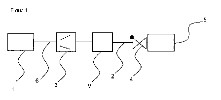
Fig. 1 is a schematic view of a device for filling a
tank with gaseous hydrogen, and
Fig. 2 is a schematic view of a pressure progression in
the filling line during a pressure and tightness test
and the ensuing filling of the tank.
Fig. 1 presents a schematic view of a device for
filling a tank with gaseous hydrogen, which exhibits an
accumulator 1 that preferably stores liquid hydrogen.
The accumulator 1 is here hooked up by means of a pump
line 6 with a pump 3, which is connected with the tank
by means of a filling line 2 and a check valve 4 of
the tank 5 to be filled.
Fig. 2 presents the schematic, chronological pressure
progression 11 in the filling line 2 while implementing
the method according to the invention. The filling line
pressure p is here plotted on the ordinate, while the
abscissa shows time t during the pressure and tightness
test and the ensuing filling of the tank 5.
A pressure rise 7 is initially observed, which is
caused by pressurizing the filling line 2 with the pump
3, but is at first too low to open the check valve 4 of
the tank 5. As soon as the check valve 4 has been
opened by the continuous pumping of the pump 3, the
pressure rise 8 levels off, since an additional volume,
specifically that of the tank 5, must be pressurized.
The tank pressure 12 prevailing in the tank 5 is now
the filling line pressure p measured in the filling
line 2. After determining the leveled pressure rise 8,
the tightness test 9 is performed, during which no
additional hydrogen is pumped into the tank 5 over a
predefined time span. If the pressure 9 in the filling

CA 02911197 2015-11-02
- 6 -
line 2 remains ideally constant, it may be concluded
that the filling line 2 is tight or the connection with
the tank 5 is sealed. As soon as the tightness test 9
has been successfully concluded, the actual filling
process takes place with a predefined pressure ramp 10.
REFERENCE LIST
1 Accumulator
2 Filling line
3 Pump
4 Check valve
Tank
6 Pump line
7 Pressure rise in filling
line
8 Leveling off of pressure
rise
9 Tightness test
Pressure ramp
11 Pressure progression
12 Tank pressure
Filling line pressure
Time
V High-pressure evaporator

Representative Drawing
A single figure which represents the drawing illustrating the invention.
Administrative Status

2024-08-01:As part of the Next Generation Patents (NGP) transition, the Canadian Patents Database (CPD) now contains a more detailed Event History, which replicates the Event Log of our new back-office solution.

Please note that "Inactive:" events refers to events no longer in use in our new back-office solution.

For a clearer understanding of the status of the application/patent presented on this page, the site Disclaimer , as well as the definitions for Patent , Event History , Maintenance Fee  and Payment History  should be consulted.

Event History

Description Date
Application Not Reinstated by Deadline 2018-06-27
Time Limit for Reversal Expired 2018-06-27
Change of Address or Method of Correspondence Request Received 2018-01-10
Deemed Abandoned - Failure to Respond to Maintenance Fee Notice 2017-06-27
Inactive: Notice - National entry - No RFE 2015-11-09
Application Received - PCT 2015-11-09
Inactive: First IPC assigned 2015-11-09
Inactive: IPC assigned 2015-11-09
National Entry Requirements Determined Compliant 2015-11-02
Application Published (Open to Public Inspection) 2015-01-08

Abandonment History

Abandonment Date Reason Reinstatement Date
2017-06-27

Maintenance Fee

The last payment was received on 2016-05-25

Note : If the full payment has not been received on or before the date indicated, a further fee may be required which may be one of the following

  • the reinstatement fee;
  • the late payment fee; or
  • additional fee to reverse deemed expiry.

Please refer to the CIPO Patent Fees web page to see all current fee amounts.

Fee History

Fee Type Anniversary Year Due Date Paid Date
Basic national fee - standard 2015-11-02
MF (application, 2nd anniv.) - standard 02 2016-06-27 2016-05-25
Owners on Record

Note: Records showing the ownership history in alphabetical order.

Current Owners on Record
LINDE AKTIENGESELLSCHAFT
Past Owners on Record
HARALD KRAUS
MICHAEL WESTERMEIER
TOBIAS KEDERER
WILFRIED-HENNING REESE
Past Owners that do not appear in the "Owners on Record" listing will appear in other documentation within the application.
Documents

To view selected files, please enter reCAPTCHA code :


To view images, click a link in the Document Description column. To download the documents, select one or more checkboxes in the first column and then click the "Download Selected in PDF format (Zip Archive)" or the "Download Selected as Single PDF" button.

List of published and non-published patent-specific documents on the CPD .

If you have any difficulty accessing content, you can call the Client Service Centre at 1-866-997-1936 or send them an e-mail at CIPO Client Service Centre.


Document
Description 
Date
(yyyy-mm-dd) 
Number of pages   Size of Image (KB) 
Description 2015-11-02 6 204
Representative drawing 2015-11-02 1 3
Claims 2015-11-02 2 48
Drawings 2015-11-02 1 6
Abstract 2015-11-02 2 85
Cover Page 2016-02-11 1 38
Notice of National Entry 2015-11-09 1 193
Reminder of maintenance fee due 2016-02-29 1 110
Courtesy - Abandonment Letter (Maintenance Fee) 2017-08-08 1 176
International search report 2015-11-02 2 55
National entry request 2015-11-02 3 85