Note: Descriptions are shown in the official language in which they were submitted.
CA 02911282 2015-11-03
WO 2013/166379
PCT/US2013/039455
COVER REMOVAL SYSTEM FOR USE IN CONTROLLED
ENVIRONMENT ENCLOSURES
FIELD OF THE INVENTION
This document relates generally to controlled environment enclosures and in
particular to a method and apparatus for removing covers from sealed
containers in
controlled environment enclosures.
BACKGROUND OF THE INVENTION
Controlled environment enclosures are known in the art and are used, for
example, for containment of hazardous materials or to provide controlled
environments with limited numbers of particulates.
In the art. controlled environment enclosures are typically fitted with ports
for transfer of materials in and out of the enclosure and the ports are fitted
with
gloves for manual manipulation of equipment, parts or materials inside the
enclosure. Such gloves are subject to significant risk of puncture, the
consequences
of which can be severe.
In some examples known in the art the controlled environment enclosure is
also used to limit exposure to viable particulates such a bacteria and fungi.
The
controlled environment enclosures may be required for aseptic processing of
cell
cultures or for the manufacture of pharmaceutical products, medical devices,
food or
food ingredients. In such applications the requirement is for the controlled
environment enclosure to be decontaminated. This can be done thermally using
steam or chemically using chemical agents. Suitable chemical agents known in
the
art include hydrogen peroxide, ozone, beta-propiolactone, aziridine,
formaldehyde,
chlorine dioxide, ethylene oxide, propylene oxide, and peracetic acid. In most
cases
the decontamination and sterilization operations have to be preceded by a
cleaning
process. Such cleaning processes have the function of removing major
contamination by simple mechanical and chemical action.
In some prior art examples the controlled environment also contains
automated equipment. Such automated equipment can include machines for
manipulation of parts or as containers, including test tubes, roller bottles,
cell culture
CA 02911282 2015-11-03
WO 2013/166379
PCT/US2013/039455
dishes, bottles, vials, ampoules and syringes. Typical examples of such
manipulations are inspection, filling and capping.
Parts to be manipulated in controlled environment enclosures can be
packaged in a container such as a tub. The container can be closed with a
cover
consisting of a sheet of flexible material, which generally is heat sealed to
the
container. The container and contents are decontaminated using a chemical
agent,
plasma or radiation.
The automated equipment located in the controlled environment is typically
of such a size and complexity that it cannot be operated fully automatically
without
human intervention. Such human intervention typically requires the use of
gloves
with the associated risk of puncture. A typical example of human intervention
that
involves the use of gloves is the removal of container covers.
SUMMARY OF THE INVENTION
In view of the above background there remains a need for an apparatus and
method for removal of container covers within controlled environments that
does
not require human intervention via the use of gloves.
In a first aspect a method is presented for removing within a controlled
environment enclosure a container cover from a sealed container, the sealed
container sealed by the container cover, the method comprising moving the
container while holding a gripping area of the container cover substantially
stationary. The moving of the container comprises holding the container with
an
articulated arm apparatus disposed within the controlled environment whilst
removing the container cover by a first manipulation of the articulated arm
apparatus. The method further comprises a second manipulating of the
articulated
arm apparatus to position along a trajectory the sealed container within a
reach of a
gripping apparatus disposed within the controlled environment, and gripping
the
gripping area with the gripping apparatus.
The positioning of the sealed container comprises placing the gripping area
of the container cover between two gripping elements of the gripping
apparatus, the
first and second of the two gripping elements respectively comprising first
and
second mutually parallel and mutually engagable grip surfaces. The method
further
comprises rotating at least one of the gripping elements. The positioning of
the
gripping area can comprise placing the gripping area proximate and
substantially
2
CA 02911282 2015-11-03
WO 2013/166379
PCT/US2013/039455
facing the first grip surface. The rotating of at least one of the gripping
elements can
comprise moving the second of the two gripping elements in a plane
substantially
parallel to the first grip surface.
The positioning of the container can further comprise straightening the
gripping area if the gripping area is bent toward the first grip surface by
contacting
to the first grip surface to one of the gripping area and a part of the cover
in contact
with the gripping area. The moving of the the second gripping element can
comprise
straightening the gripping area if the gripping area is bent toward the second
gripping element by contacting the second grip surface to the other of the
gripping
area and the part of the cover in contact with the gripping area.
The method can further comprise lowering the container or rotating the
container about an axis substantially in the plane of the cover. This is done
by a
third manipulating of the articulated arm apparatus. The rotating or raising
of the
gripping area is to an extent that allows the gripping apparatus to remain
clear of the
container during the removing the container cover.
The removing the container cover can be removing the container cover
simultaneously along two edges of the container. The first manipulating of the
articulated arm apparatus can comprise moving the container with respect to
the
gripping apparatus. Moving the container with respect to the gripping
apparatus can
comprise moving the container substantially diagonally with respect to the
gripping
apparatus. The moving the container with respect to the gripping apparatus can
comprise moving the container along a predetermined path within a
predetermined
space.. One or both of the predetermined path and the predetermined space can
be
determined using a controller. The predetermined path can be a circular path.
The trajectory of the container can be based on information obtained from a
sensor. The information can comprise one or both of position information and
orientation information about the gripping area.
The method can further comprise inspecting the container cover using a
sensor. The method can further comprise selecting an alternative gripping area
of
the container cover based on the inspecting; gripping the alternative gripping
area
with the gripping apparatus; and removing the container cover by moving the
container.
3
CA 2911282 2017-05-23
CA 2911282
The method can further comprise moving the gripping apparatus away from an
operational area
of the articulated arm apparatus after removing the container cover.
In a further aspect there is provided an apparatus comprising a controlled
environment enclosure;
and within the controlled environment enclosure an articulated arm apparatus
and a rotary gripping
apparatus. The articulated arm apparatus can be configurable for holding and
moving a container in three
dimensions; and the rotary gripping apparatus can be configured for gripping a
gripping area of a
container cover sealing the container. The rotary gripping apparatus can
comprise two gripping elements
having facing mutually engagable surfaces, at least one of the two gripping
elements being rotatable about
a common axis with the other of the two gripping elements to grip the gripping
area of the container cover
between the two facing mutually engagable surfaces. The the articulated arm
apparatus can comprise at
least two arm segments, at least one arm segment being configurable to hold
the container.
The articulated arm apparatus and the rotary gripping apparatus can be
separated by a distance
large enough for the gripping apparatus to not interefere with the working of
the articulated arm
apparatus. The apparatus can further comprise a controller for controlling at
least the articulated arm
apparatus and the gripping apparatus. The moving the container can be moving
the container along a path
that is determined by the controller and the moving the container is contained
within a space determined
by the controller.
The apparatus can further comprise a sensor configured for supplying
information to the
controller for determining at least one of a location of the container cover
gripping area and an orientation
of the container cover. The articulated arm apparatus can be at least one of
automatically controlled and
reprogrammable. The gripping apparatus can be at least one of automatically
controlled and
reprogrammab le.
Various embodiments of the claimed invention pertain to a method for removing
within a
controlled environment enclosure a container cover from a sealed container,
the sealed container sealed
by the container cover, the method comprising moving the container while
holding a gripping area of the
container cover substantially stationary, wherein moving the container
comprises holding the container
with an articulated arm apparatus disposed within the controlled environment,
and removing the container
cover is by a first manipulating of the articulated arm apparatus.
Various embodiments of the claimed invention also pertain to an apparatus for
removing within a
controlled environment enclosure a container cover from a sealed container
comprising the controlled
environment enclosure; and within the controlled environment enclosure an
articulated arm apparatus and
a rotary gripping apparatus, wherein the articulated arm apparatus is
configurable for
4
CA 2911282 2017-05-23
CA 2911282
holding and moving the container in three dimensions, andthe rotary gripping
apparatus is configured for
gripping a gripping area of the container cover sealing the container.
BRIEF DESCRIPTION OF THE DRAWINGS
In the drawings, which are not necessarily drawn to scale, like numerals may
describe similar
components in different views. Like numerals having different letter suffixes
may represent different
instances of similar components. The
4a
CA 02911282 2015-11-03
WO 2013/166379
PCT/US2013/039455
drawings illustrate generally, by way of example, but not by way of
limitation,
various embodiments discussed in the present document.
FIG. 1 shows a controlled environment enclosure containing an articulated
arm apparatus for handling of containers and an apparatus for gripping of
container
covers.
FIG. 2 shows an example of a container.
FIG. 3 shows a detail view of a container showing an example of the cover
extending outside the outline of the top surface of the container.
FIG. 4 shows a gripping apparatus with gripping jaws partially opened.
FIG. 5 shows a top view perspective of an articulated arm apparatus and
gripping apparatus near an initial stage of removal of a cover from a
container.
FIG. 6 shows a top view perspective of an articulated arm apparatus and
gripping apparatus at a first intermediate stage of removal of a container
cover from
a container.
FIG. 7 shows a top view perspective of an articulated arm apparatus and
gripping apparatus at a second intermediate stage of removal of a container
cover
from a container.
FIG. 8 shows a top view perspective of an articulated arm apparatus and
gripping apparatus at near complete stage of removal of a container cover from
a
container
FIG. 9A is a flow diagram for a method to remove a cover of a container in
a controlled environment enclosure.
FIG.9B is a more detailed flow diagram of part of the method of FIG. 9A.
FIG. 9C is a more detailed flow diagram of part of the method of FIG. 9A.
FIG. 10A is a flow diagram for a further method to remove a cover of a
container in a controlled environment enclosure.
FIG. 10B is a more detailed flow diagram of part of the method of
FIG.10A.
FIG. 10C is a more detailed flow diagram of part of the method of
FIG.10A.
FIG. 11 is a more detailed flow diagram of part of FIG. 9A and FIG. 10A.
CA 02911282 2015-11-03
WO 2013/166379
PCT/US2013/039455
DETAILED DESCRIPTION
FIG. 1 shows an apparatus 100 comprising a controlled environment
enclosure 120, a gripping apparatus 113 and an articulated arm apparatus 115,
both
inside the controlled environment enclosure 120 and arranged for positioning
and
relocation of a container 114 within the controlled environment enclosure 120
without requiring direct human intervention and the associated use of gloves.
Container 114 can be, for example, a tub. The term "tub- as used herein is
used to
describe any container suitable for holding parts, trays of nested
arrangements of
parts, a stack of trays with nested arrangements of parts, or combinations
thereof.
The apparatus 100 can further comprise of a sensor 160 for sensing the
container 114.
The controlled environment enclosure 120 can comprise windows 121, an
inlet filter 130, an inlet valve 131, a blower 132, an outlet filter 133 and
an outlet
valve 134. The characteristics of blower 132, inlet filter 130, and outlet
filter 133 are
chosen to yield a controlled environment inside controlled environment
enclosure
120. The contents of the controlled environment enclosure 120 can be protected
by
airflow while having one or more openings (not shown).
In another embodiment the controlled environment enclosure 120 can be
fully sealed and be operated at a positive or negative pressure differential
relative to
the surroundings. Those skilled in the art will understand that several other
filter and
blower arrangements can be used to establish a controlled environment inside
controlled environment enclosure 120. A suitable controlled environment can be
obtained, for example without limitation, by means of any one or more of
turbulent
airflow, horizontal unidirectional airflow and vertical unidirectional
airflow.
The operation of the gripping apparatus 113 and the articulated arm
apparatus 115 is controlled by a means located outside of environment
enclosure
120. In some embodiments the means of controlling apparatus 113, apparatus 115
and enclosure 120 require a local or remote operator input device such as joy
stick
control, push button control, emergency stop, touch screen human machine
interface, keyboard, mouse, handheld device or the like. Typically one or more
of
such input devices are connected to a controller 140. In FIG.!, a laptop
computer
programmed with suitable software is shown as an example of controller 140. In
other embodiments controller 140 can be a variety of other means such as
operator
interface panel, programmable logic controller, programmable automation
6
CA29I1282
controller, a desktop computer or a remote I/0 module with embedded logic
functions. In some
embodiments the controller 140 can consist of a plurality of the aformentioned
controllers.
The controller 140 provides control instructions to apparatus 100 over control
line 150.
Control line 140 is a schematic representation of all of the required
mechanical linkages, electrical
wiring, pneumatic, hydraulic and wireless connections to operate apparatus
100.
The container 114 can be manipulated inside the controlled environment
enclosure 120 by
mechanical means, for example, an articulated arm apparatus 115. Suitable
robotic arm manipulation
systems for mechanically manipulating the container 114 include, but are not
limited to, 6-axis
robotic arms, Selective Compliant Articulated Robot Arm (SCARA) systems, r-
theta robots, and
assemblies of linear actuators and rotary actuators, or combinations thereof.
In one embodiment of the apparatus 100 the articulated arm apparatus 115 can
be the
articulated arm apparatus described in US Provisional Patent Application
61/596,698.
The controlled environment enclosure 120, in some examples, includes a sensor
160 for
sensing the container 114 and a container cover 116 for the container 114. In
the example shown in
FIG. !the sensor is mounted to the top surface of the controlled environment
enclosure 120. In other
embodiments it can be mounted at another suitable location to monitor the
interior of controlled
environment enclosure 120. The sensor 160, in one example is an optical
sensor. In other examples
the sensor 160 can be one of a variety of other types of sensors, such as a
camera system, a laser
system or an ultrasonic sensing system. In yet other examples the sensor 160
is an assembly that
consists of a plurality of sensing elements. The sensor 160 has a sensing cone
(not shown) or
multiple sensing cones than can cover a small, a large area or both; depending
on the characteristics
of the sensor 160 used.
In other embodiments of this invention the controlled environment chamber 120
contains
articulated arm apparatus 115 plus at least one further articulated arm
apparatus (not shown in the
interest of clarity). The additional at least one further articulated arm
apparatus can be used, for
example, for activities that can follow removal of the container cover 116
from the container 114.
Apparatus 100 can be used for functions preceding the function of the filling
system described in US
patent application 12/393,183.
In yet another embodiment gripping apparatus 113 is added to a filling system
as described
in United States Patent Application 61/033,682, with element 30 of United
States
7
CA 2911282 2017-11-10
CA2911282
Patent Application 61/033,682 as the equivalent of articulated arm apparatus
115 of the present
specification, chamber 20 of United States Patent Application 61/033,682 as
the equivalent of
controlled environment enclosure 120 of the present specification, and optical
sensor 12 of
United States Patent Application 61/033,682 as the equivalent of sensor 160 of
the present
specification. United States Patent Application 61/033,682.
The articulation of arm apparatus 115 can be remoted operated by the operator.
In
another embodiment the articulated arm apparatus 115 can be an automatically
controlled
articulated arm. In yet another embodiment the articulated arm apparatus can
be a
reprogrammable automatically controlled articulated arm.
FIG. 2 shows a bottom view of an example of the container 114. The container
114 can
be made of a metal, glass, plastic or a composite material, but typically the
tub 114 is a single use
thin walled container. Thin walled single use containers are typically made by
a low cost
process, such as thermoforming or injection molding. As shown in FIG 2, the
container 114 can
have features such as tapered sidewalls that assist in manufacturability, but
are more difficult to
hold than an object with rigid parallel walls. All four walls forming the
sides of the container 114
can have a step 201.
FIG. 3 shows a detail view of container 114. The kind of container 114
typically
employed in the pharmaceutical industry is characterized by a top lip 302 that
provides a surface
area for a sealed connection to the container cover 116. The term "cover" is
used here to describe
any surface material, including but not limited to a flexible sheet made of
plastic material, a
polymeric membrane or an impermeable laminated foil.
The container cover 116 can extend outside the outline of the top lip 302 of
the tub 114 in
at least one location, and typically extends outside the outline of the top
lip 302 in a plurality of
locations. The at least one area of container cover 116 that extends outside
the outline of the top
lip 302 provides a gripping area 301 that can be used as access for clamping.
Clamping on the
gripping area 301 can be complicated by the flexibility of the material of the
container cover
116. The gripping area 301 can be level, bent upwards, or bent downwards.
8
CA 2911282 2017-10-02
CA 02911282 2015-11-03
WO 2013/166379
PCT/US2013/039455
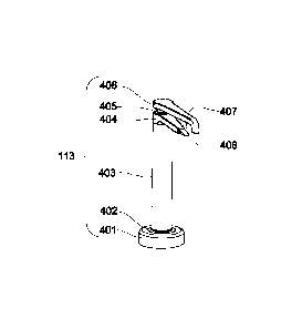
FIG 4 shows an example embodiment of the gripping apparatus 113. An
upper arm 406 is rotatably connected to a main shaft 403 by a radial seal 405.
The
main shaft 403 is rigidly connected to a lower arm 404 by a fully sealed
joint. The
main shaft 403 is rotatably connected to a base flange 401 by a radial seal
402. The
base flange 401 is sealably connected to controlled environment enclosure 120.
The
tip of lower arm 404 and the tip of upper arm 406 have mutually facing and
mutually engagable grip surfaces 407 and 408 respectively such that the
mutually
facing flat grip surfaces 407 and 408 are mutually engagable in the absence of
any
material, such as container cover material, being disposed between the
surfaces. The
grip surface 407 can be an upper surface of the tip of lower arm 404 and the
grip
surface 408 can be a lower surface of the tip of the upper arm 406.
In one embodiment of the gripping apparatus 113 the lower arm 404 is
stationary and upper arm 406 is rotatable about a cylindrical axis of main
shaft 403.
In another embodiment of the gripping apparatus 113 the upper arm 406 is
stationary and lower arm 404 is rotatable about the cylindrical axis of main
shaft
403. In yet a further embodiment both upper arm 406 and lower arm 404 are
rotatable about the cylindrical axis of main shaft 403.
The gripping apparatus 113 can be remotely operated by the operator. In
another embodiment the gripping apparatus 113 can be automatically controlled.
In
yet another embodiment the gripping appartatus 113 can be a reprogrammable
automatically controlled gripping apparatus.
We now describe at the hand of FIG.!, FIG.2, FIG.3, and FIG.4, as well as
the flow diagrams in FIG.9A, FIG.9B, FIG.9C, FIG.10A, FIG.10B, FIG.10C and
FIG.11, a method for using the apparatus 100 to remove the cover 116 of the
container 114. The method comprises using the sensor 160 to detect an
orientation
of the gripping area 301, and to communicate with the controller 140 over
control
line 150. The method further comprises planning the trajectory of the
container 114
using the controller 140 so that gripping apparatus 113 can access the
gripping area
301.
In one example embodiment, shown in FIG.9A and expanded on in FIG.9B
and FIG.9C, the method comprises the sensor 160 sensing [510] information
concerning the gripping area 301 and communicating [512] the sensed infomation
to
the controller 140 over control line 150. The sensed information can be the
position
of the gripping area 301 or the orientation of gripping area 301 or both. The
sensed
9
CA 02911282 2015-11-03
WO 2013/166379
PCT/US2013/039455
infomation can be used as input information by the controller 140 for
determining
[514] a trajectory for the articulated arm apparatus 115 along which to
position the
sealed container 114 within a reach of the gripping apparatus 113.
The cover gripping sequence can be initiated by rotating [520] the upper arm
406 and the lower arm 404 of the gripping apparatus 113 with respect to each
other
by an angle that separates the mutually facing grip surfaces 407 and 408
located on
respectively lower arm 404 and upper arm 406 by at least the width of the
container
114. This can be done by rotating one or both of the arms 406 and 404.
The method further comprises manipulating [530] articulated arm apparatus
115 to move the container 114 along the trajectory that places the gripping
area 301
above the grip surface 407 of the lower arm 404. This has the result of moving
[532]
the container 114 towards the lower arm 404 in a trajectory that results in a
bottom
surface of the top lip 302 of container 114 nearing or contacting the grip
surface 407
of the lower arm 404. At least during the last section of the approach, the
container
114 can be moved to cause the bottom surface of the top lip 302 to
substantially
slide along the grip surface 407 of the lower arm 404. During this section of
the
approach, the tip of the lower arm 404 can be bending [534] the gripping area
301
upward in the case where gripping area 301 happens to be orientated downward
to
below the top lip 302.
The method further comprises rotating [540] upper arm 406 to grip the
gripping area 301. This comprises moving [542] the tip of upper arm 406
comprising the surface 408 over the container cover 116 during its travel to
the
gripping area 301. As the upper arm 406 approaches the gripping area 301, it
can
slide over the container cover 116 above the top surface of top lip 302.
During this
action, the tip of the upper arm 406 can be bending [544] down to a
substantially
horizontal orientation any upward bent parts of cover 116, including
specifically the
gripping area 301.
In another example embodiment of the method, shown in FIG.10A and
expanded on in FIG.10B and FIG10C, the sensor 160 also senses the orientation
of
the gripping area 301 and communicates the sensed orientation to the
controller 140
over control line 150. The sensed orientation of the gripping area 301 can, as
before,
be used as input information by controller 140 to determine a trajectory for
the
articulated arm apparatus 115 along which to position the sealed container 114
within a reach of the gripping apparatus 113.
CA 02911282 2015-11-03
WO 2013/166379
PCT/US2013/039455
The cover gripping sequence can, as above, be initiated with the rotating
[550] of the upper arm 406 and the lower arm 404 of the gripping apparatus 113
with respect to each other by an angle that separates the mutually facing grip
surfaces 407 and 408 located on respectively lower arm 404 and upper arm 406
by
at least the width of the container 114.
The method further comprises manipulating [560] articulated arm apparatus
115 to move the container 114 along the trajectory that places the gripping
area 301
below the grip surface 408 of the upper arm 406. This has the result of moving
[562]
the container 114 towards the upper arm 406 in a trajectory that results in a
top
surface of the top lip 302 of container 114, covered by cover 116, nearing or
contacting the grip surface 408 of the upper arm 406. At least during the last
section
of the approach, the container 114 can be moved to cause the top surface of
the top
lip 302, covered by cover 116, to substantially slide along the surface 408 of
the
upper arm 406. During this section of the approach, the tip of the upper arm
406 can
be bending [564] the gripping area 301 downward in the case where gripping
area
301 happens to be orientated upward to above the top lip 302.
The method further comprises rotating [570] the lower arm 404 to grip the
gripping area 301. This comprises moving [572] the tip of lower arm 404
comprising the grip surface 407 under the bottom surface of top lip 302 during
its
travel to the gripping area 301. As the lower arm 404 approaches the gripping
area
301, it can slide along the bottom surface of top lip 302. During this action,
the tip
of the lower arm 404 can be bending [574] up to a substantially horizontal
orientation any downward bent parts of cover 116, including specifically the
gripping area 301.
The gripping apparatus 113 works for a wide range of thickness of the
container cover 116 by clamping the gripping area 301 of container cover 116
in
between the mutually facing grip surfaces 407 and 408 located on respectively
the
lower arm 404 and the upper arm 406.
The method provides for removing [580] the container cover 116 in the
controlled environment enclosure 420. This is shown in expanded form in
FIG.11.
Once the gripping apparatus 113 has gripped the gripping area 301 and is
holding
the gripping area 301 substantially stationary, the method can proceed further
with
manipulating [582] the articulated arm apparatus 120 to either lower the
container
114 or rotate the container 114 about an axis substantially in the plane of
the cover.
11
CA 02911282 2015-11-03
WO 2013/166379
PCT/US2013/039455
This manipulating [582] is to a degree that positions and/or orients the
container 114
and cover 116 such that clearance is established for the two arms 404 and 406
of the
gripping apparatus 113 to clear the cover 116 and container 114 during the
subsequent removal of the cover 116 from the container 114.
Referring to the articulated arm apparatus 115 and the gripping apparatus
113 as shown in FIGS 5-8, the container cover 116 can be removed by moving the
container 114 in a substantially diagonal trajectory by manipulating [584]
articulated arm apparatus 115 while the gripping apparatus 113 is holding the
gripping area 301 substantially stationary. The term "substantially diagonal
is used
in this specification to describe a direction of motion parrallel to the
diagional of the
container 114 between the two sides of the container 114 that teminate jointly
at the
location of the gripping area 301. The substantially diagonal trajectory
minimizes a
total length of adhesive that is being opened at any given time. As shown in
FIGS
5-8, the substantially diagonal trajectory can be obtained by rotating the
articulated
arm apparatus 115 in direction A. This particular choice of motion can keep
all
moving parts participating in removing the container cover 116 confined to a
small
space within the controlled environment enclosure 420. The controller 140 can
be
configured for predetermining the small space before the motion is conducted
by
predetermining the path for the container 114 to follow while being held by
the
articulated arm apparatus 115. The predetermined path can be, but is not
limited to,
a cicular path.
In another embodiment the container cover 116 can be removed by a more
general direction of motion of container 114 by manipulating [584] articulated
arm
apparatus 115 while the gripping apparatus 113 is holding the gripping araea
301
substantially stationary. In this embodiment the articulated arm apparatus 115
is not
limited to being rotated. This motion of the container 114 can be executed in
a
fashion and direction such as to remove the container cover 116 simultaneously
along two edges of the container 114, starting from the gripping area 301.
FIGS 5-8 provide an example of removal of the container cover 116 by a
pushing motion of articulated arm apparatus 115. In a further embodiment, the
container cover 116 can be removed in a pulling motion by articulated arm
apparatus 115.
The sensor 160 can be used for verifying the completeness of removal of the
container cover 116. If, for some undetermined reason, the gripping apparatus
113
12
CA2911282
were to lose its grip on the container cover 116 during the removal of the
container cover 116,
the articulated arm apparatus 115 can continue moving the containcr 114 with
the partially
removed container cover 116. In the event of such partial removal of container
cover 116; the
previously described process of orienting substantially horizontally any up-or
downward bent
areas of the cover 116, including the gripping area 301, can be repeated after
the articulated arm
apparatus 115 repositions the gripping area 301 near the tip of the lower arm
404. If the gripping
area 301 were to be no longer available, for example if the gripping area 301
were torn off, the
process of gripping the gripping area 301 can be repeated after redirecting
the articulated arm
apparatus 115 to another suitable available gripping area 301.
For the sake of clearly differentiating between the different manipulations
that are
undertaken by the articulated arm apparatus 120, we refer to the manipulating
[584] of the
articulated arm apparatus 120 to remove the cover 116 as a "first
manipulation", and the
manipulating [530] and [560] of the articulated arm apparatus 120 to position
the container 114
between the lower arm 402 and the upper arm 406 as a "second manipulating",
while we refer to
the manipulating [582] of the articulated arm apparatus 120 to lower the
container 114 or to
rotate the container 114 about an axis substantially in the plane of the cover
116 as a "third
manipulating". The gripping apparatus 113 is not limited to the example shown
in FIG 4. In
other embodiments the gripping apparatus 113 can comprise a pair of prongs
with narrow gap in
between, one of which slides over and the other slides under the gripping
area, thereby clamping
the cover by friction caused by rotation of both prongs. In yet another
embodiment the gripper
can be of the type described in German Patent DE4419475. In yet other
embodiments the gripper
apparatus can comprise gripping devices that are commercially available, such
as parallel
grippers, angular grippers or inflatable bellow grippers.
ADDITIONAL NOTES
The drawings and the associated descriptions are provided to illustrate
embodiments of
the invention and not to limit the scope of the invention. Reference in the
specification to "one
embodiment" or "an embodiment" is intended to indicate that a particular
feature, structure, or
characteristic described in connection with the embodiment is included in at
least an embodiment
of the invention. The
13
CA 2911282 2017-10-02
CA 02911282 2015-11-03
WO 2013/166379
PCT/US2013/039455
appearances of the phrase "in one embodiment" or "an embodiment" in various
places in the specification are not necessarily all referring to the same
embodiment.
As used in this disclosure, except where the context requires otherwise, the
term "comprise" and variations of the term, such as "comprising," "comprises"
and
"comprised" are not intended to exclude other additives, components, integers
or
steps.
In the foregoing specification, the invention has been described with
reference to specific embodiments thereof. It will, however, be evident that
various
modifications and changes may be made thereto without departing from the
broader
spirit and scope of the invention. The specification and drawing are,
accordingly, to
be regarded in an illustrative rather than a restrictive sense. It should be
appreciated
that the present invention should not be construed as limited by such
embodiments.
From the foregoing description it will be apparent that the present invention
has a number of advantages, some of which have been described herein, and
others
of which are inherent in the embodiments of the invention described or claimed
herein. Also, it will be understood that modifications can be made to the
device,
apparatus and method described herein without departing from the teachings of
subject matter described herein. As such, the invention is not to be limited
to the
described embodiments except as required by the appended claims.
PARTS LIST
100 apparatus
113 gripping apparatus
114 container
115 articulated arm apparatus
116 container cover
120 controlled environment enclosure
140 controller
150 control line
160 sensor
121 window
130 inlet filter
131 inlet valve
132 blower
14
CA 02911282 2015-11-03
WO 2013/166379
PCT/US2013/039455
133 outlet filter
134 outlet valve
201 step
301 gripping aea
302 top lip
401 base flange
402 radial seal
403 main shaft
404 lower arm
405 radial seal
406 upper arm
407 grip surface
408 grip surface
[5101 sensing the orientation of the gripping area
[512] communicating the sensed orientation to
[514] determining a trajectory
[520] rotating the upper arm and the lower arm with respect to each other
[530] manipulating the articulated arm apparatus
[532] moving the container toward the lower arm
[534] bending up the gripping area
[540] rotating the upper arm to grip the gripping area
[542] moving the tip of the upper arm over the container cover
[5441 bending down bent parts of the cover including the gripping area
[550] rotating the upper arm
[560] manipulating the articulated arm apparatus
[562] moving the container toward the upper arm
[564] bending down the gripping area
[570] rotating the lower arm to grip the gripping area
[572] moving the tip of lower arm under the bottom surface of the container
top lip
[574] bending up bent parts of the cover including the gripping area
[580] removing the container cover
[582] manipulating the articulated arm apparatus to establish clearance for
arms
[584] moving the container in a substantially diagonal trajectory