Note: Descriptions are shown in the official language in which they were submitted.
14-MCB-214
-1-
ELECTRICAL SWITCHING APPARATUS, AND INDICATION ASSEMBLY AND
TRIP CAM THEREFOR
10 BACKGROUND
Field
The disclosed concept pertains generally to electrical switching apparatus
such as
for example, circuit breakers. The disclosed concept also pertains to
indication assemblies for
electrical switching apparatus. The disclosed concept further relates to trip
cams for indication
assemblies.
Background Information
Electrical apparatus, such as electrical switching apparatus or electrical
meters
used in power distribution systems, are often mounted on or within an
electrical enclosure (e.g.,
without limitation, a panelboard; a load center; a meter breaker panel) either
individually or in
combination with other electrical meters or switchgear (e.g., without
limitation, circuit switching
devices and circuit interrupters such as circuit breakers, contactors, motor
starters, motor
controllers and other load controllers). Such circuit breakers are used to
protect electrical
circuitry from damage due to a trip condition, such as, for example, an
overcurrent condition, an
overload condition, an undervoltage condition, a relatively high level short
circuit or fault
condition, a ground fault or arc fault condition.
Molded case circuit breakers, for example, include at least one pair of
separable
contacts which are operated either manually by way of a handle disposed on the
outside of the
case, or automatically by way of a trip unit in response to the trip
condition. Generally, the trip
unit includes a cradle assembly which is operable between a latched
configuration during normal
4340805
Date Recue/Date Received 2020-11-02
CA 02911301 2015-11-04
14-MCB-214
circuit breaker operation, and an unlatched position in which the separable
contacts are tripped
open, in response to the trip condition.
Known circuit breakers include mechanisms that allow the tripping of one pole
to
cause other poles to trip, and further include mechanisms that provide a
visual indication that the
circuit breaker has tripped. Such mechanisms are complex and take up
significant space within
the circuit breaker.
There is thus room for improvement in electrical switching apparatus, and in
indication assemblies and trip cams therefor.
SUMMARY
These needs and others are met by embodiments of the disclosed concept wherein
a trip cam is provided which among other benefits, enables circuit status of
an electrical
switching apparatus to be determined.
In accordance with one aspect of the disclosed concept, a trip cam for an
indication assembly of an electrical switching apparatus is provided. The
electrical switching
apparatus comprises a housing and a number of poles, each of the number of
poles comprising a
pair of separable contacts and an operating mechanism structured to open and
close the separable
contacts, the indication assembly comprising a cradle member, the trip cam
comprising: a
mounting portion; a transfer leg extending from the mounting portion, the
transfer leg being
structured to cooperate with each of the number of poles; a driving leg
extending from the
mounting portion in a first direction, the driving leg being structured to be
driven by the cradle
member; and a trip indicator leg comprising a base portion. The base portion
extends from the
mounting portion in a second direction generally opposite the first direction.
As another aspect of the disclosed concept, an indication assembly for an
electrical switching apparatus is provided. The electrical switching apparatus
comprises a
housing and a number of poles, each of the number of poles comprising a pair
of separable
contacts and an operating mechanism structured to open and close the separable
contacts, the
indication assembly comprising: a cradle member structured to engage the
housing; and a trip
cam comprising: a mounting portion, a transfer leg extending from the mounting
portion, the
transfer leg being structured to be cooperate with each of the number of
poles, a driving leg
CA 02911301 2015-11-04
14 -MCB-214
-3-
extending from the mounting portion in a first direction, the driving leg
being structured to be
driven by the cradle member, and a trip indicator leg comprising a base
portion. 'The base
portion extends from the mounting portion in a second direction generally
opposite the first
direction.
As a further aspect of the disclosed concept, an electrical switching
apparatus is
provided. 'fhe electrical switching apparatus comprises: a housing; a number
of poles, each of
the number of poles comprising a pair of separable contacts and an operating
mechanism
structured to open and close the separable contacts; and at least one
indication assembly
comprising: a cradle member disposed in the housing, and a trip cam
comprising: a mounting
portion, a transfer leg extending from the mounting portion, the transfer leg
cooperating with
each of the number of poles, a driving leg extending from the mounting portion
in a first
direction, the driving leg being structured to be driven by the cradle member,
and a trip indicator
leg comprising a base portion. The base portion extends from the mounting
portion in a second
direction generally opposite the first direction.
BRIEF DESCRIPTION OF THE DRAWINGS
A full understanding of the disclosed concept can be gained from the following
description of the preferred embodiments when read in conjunction with the
accompanying
drawings in which:
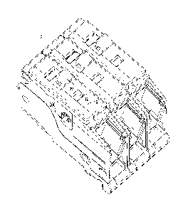
Figure 1 is an isometric view of an electrical switching apparatus, in
accordance
with an embodiment of the disclosed concept;
Figure 2 is an elevation view of the electrical switching apparatus of Figure
1, shown
with the movable arm in the CLOSED position and with portions of the
electrical switching
apparatus removed to show hidden structures;
Figure 3 is an elevation view of the electrical switching apparatus of Figure
2,
showing the movable arm in an open position;
Figure 4 is an elevation view of the electrical switching apparatus of Figure
2,
showing the movable arm in an EXTENDED OPEN position;
Figure 5 is an isometric view of a portion of the contact assembly for the
electrical
__ switching apparatus of Figure 4;
CA 02911301 2015-11-04
14-MCB-214
-4-
Figure 6 is an isometric view of a portion of the housing for the electrical
switching
apparatus of Figure 4;
Figures 7A-7F are different views of a trip cam for the electrical switching
apparatus
of Figure 1;
Figure 8 is an elevation view of an indication assembly for the electrical
switching
apparatus of Figure 1, shown in the loaded position;
Figure 9 is an elevation view of the indication assembly of Figure 8, shown in
the
unloaded position;
Figure 10 is an isometric view of an operating handle assembly for the
electrical
switching apparatus of Figure 1, showing the cradle member in the TRIPPED
position;
Figure 11 is an elevation view of the operating handle assembly of Figure 10
as
employed in a portion of the electrical switching apparatus, showing the
cradle member in the
CLOSED position; and
Figure 12 is an elevation view of the operating handle assembly of Figure 11,
showing the cradle member in the TRIPPED position.
DESCRIPTION OF THE PREFERRED EMBODIMENTS
As employed herein, the term "number" shall mean one or an integer greater
than
one (i.e., a plurality).
As employed herein, the statement that two or more parts are "connected" or
"coupled" together shall mean that the parts are joined together either
directly or joined through
one or more intermediate parts.
As employed herein, the statement that two or more parts or components
"engage" one another shall mean that the parts touch and/or exert a force
against one another
either directly or through one or more intermediate parts or components.
Figure 1 shows an electrical switching apparatus (e.g., without limitation,
circuit
breaker 2) in accordance with the disclosed concept. The example circuit
breaker 2 includes a
housing 10, a number of operating handles (one operating handle 50 is
indicated) extending into
the housing 10, and a number of trip cams (only one trip cam 200 is partially
visible in Figure 1)
located within the housing 10.
CA 02911301 2015-11-04
14-MCB-214
-5-
Figures 2 through 4 show different views of the circuit breaker 2 with
portions
removed in order Co see internal components. As seen, the circuit breaker 2
further includes a
cradle member 40 located in and engaging the housing 10, an operating
mechanism (e.g., without
limitation, spring 60) coupled to the cradle member 40, and a contact assembly
100. The circuit
breaker 2 has a number of poles and a corresponding contact assembly (e.g.,
without limitation,
substantially similar to or the same as the contact assembly 100) for each of
the poles of the
circuit breaker 2.
Continuing to refer to Figures 2 through 4, the contact assembly 100 includes
a
stationary contact 102 located in the housing 10, and a movable arm 110. The
movable arm 110
has a movable contact 112 structured to engage the stationary contact 102. As
will be discussed
in greater detail hereinbelow, the movable arm 110 is structured to move
between a CLOSED
position (Figure 2) and an EXTENDED OPEN position (Figure 4). In order to
maintain the
movable arm 110 in the EXTENDED OPEN position (Figure 4), the contact assembly
100
advantageously further includes an extension apparatus 150 located on the
housing 10.
As seen in Figure 5, the extension apparatus 150 includes a generally U-shaped
link member 170 and an elongated extension 160 located on the movable arm 110.
The link
member 170 is coupled to the elongated extension 160 and further structured to
be located on
and engage the housing 10, as will be discussed below. The movable arm 110
includes a distal
portion 120 located proximate the movable contact 112 and opposite the
elongated extension
160. Furthermore, the movable arm 110 has a cutout 122 located between the
elongated
extension 160 and the distal portion 120. In operation, the operating handle
50 is structured to be
located in the cutout 122, as shown in Figure 4. Additionally, the elongated
extension 160
extends from the movable arm 110 proximate the cutout 122. In the example non-
limiting
embodiment, the elongated extension 160 is integral with the movable arm 110.
Stated
differently, the movable arm 110, and thus the elongated extension 160,
preferably form a single
unitary component composed of the same single piece of material (as opposed to
a plurality of
separate components being joined together). However, it will be appreciated
that an elongated
extension (not shown) may be an individual component separately coupled to a
movable arm
(not shown), without departing from the scope of the disclosed concept.
CA 02911301 2015-11-04
14-MCB-214
-6-
Continuing to refer to Figure 5, the link member 170 includes a pair of
opposing
legs 172 (partially shown in hidden line drawing),174 and a middle portion 176
generally normal
to the legs 172,174 and connecting the leg 172 to the leg 174. As seen, the
elongated extension
160 includes a pair of spaced apart and opposing end portions 161,163.
Furthermore, the
elongated extension 160 has an aperture 162 located proximate the end portion
161. The leg 172
of the link member 170 at least partially extends into the aperture 162 of the
elongated extension
160 in order to couple the link member 170 to the elongated extension 160, and
thus the movable
arm 110. Moreover, the movable contact 112 includes a contact surface 118
located in a plane
(indicated generally as 118-1), and the elongated extension 160 has a
longitudinal axis 160-1 at
an angle 130 with the plane 118-1. As seen, the angle 130 is preferably
greater than 90 degrees.
It will be appreciated that when the movable arm 110 is in the EXTENDED OPEN
position, the
extension apparatus 150, and particularly the configuration of the elongated
extension 160 and its
relation with the link member 170, and internal portion 14 of housing 10,
advantageously enables
the movable arm 110 to be maintained in the EXTENDED OPEN position (Figure 4),
as will be
discussed in greater detail hereinbelow. It will also be appreciated that an
extension apparatus
(not shown) may have any known or suitable alternative shape and/or
configuration to perform
the desired function of maintaining the movable arm 110 in an EXTENDED OPEN
position.
Figure 6 shows a portion of the example housing 10. As seen, the housing 10
includes a wall portion 12 and an internal portion 14 adjacent the wall
portion 12. The internal
portion 14 has a slot 20 that has a pair of opposing and spaced apart end
portions 22,24 and a
center portion 26 located generally midway between the end portions 22,24. The
end portion 22
is adjacent the wall portion 12 and the end portion 24 is internal with
respect to the wall portion
12.
Referring again to Figure 2, in which the movable arm 110 is in the CLOSED
position, the leg 174 of the link member 170 is located on the housing 10
proximate the center
portion 26 of the slot 20 (i.e., spaced from the end portion 22). Although the
leg 174 partially
extends into the slot 20, it is within the scope of the disclosed concept for
an internal portion (not
shown) to alternatively include a slot for a leg (not shown) to extend
entirely therethrough.
Additionally, the middle portion 176 of the link member 170 has a longitudinal
axis 176-1 that is
generally normal to the plane 118-1 of the contact surface 118, as shown.
CA 02911301 2015-11-04
14-MCB-214
-7-
Furthermore, Figure 2 shows the operating handle 50 is in an ON position.
Responsive to the operating handle 50 moving from the ON position toward an
OFF position
(Figures 3 and 4), the movable arm 110 moves from the CLOSED position (Figure
2) toward the
EXTENDED OPEN position (Figure 4). It will further be appreciated that
responsive to the
movable arm 110 moving from the CLOSED position (Figure 2) toward the EXTENDED
OPEN
position (Figure 4), the cradle member 40 remains substantially stationary. In
other words, the
example extension apparatus 150 is significantly advantageous when the
operating handle 50 is
manually moved between ON and OFF positions.
Figure 3 shows the movable arm 110 in an open position. For ease of
illustration
and purposes of discussion, the contact assembly 100 is illustrated in Figure
3 without the link
member 170 (Figures 2, 4 and 5). As will be discussed below, by incorporating
the link member
170 with the elongated extension 160, the movable arm 110 is advantageously
able to be
maintained in the EXTENDED OPEN position (Figure 4). Additionally, in the open
position of
Figure 3, the spring 60 is in a static position in which it does not tend to
cause the movable arm
110 to rotate one direction or the other. Furthermore, as seen, the movable
contact 112 is spaced
a distance 114 from the stationary contact 102.
Figure 4 shows the movable arm 110 in the EXTENDED OPEN position. In this
position, the movable contact 112 is spaced a distance 116 from the stationary
contact 102. The
distance 116 (Figure 4) is greater than the distance 114 (Figure 3). In other
words, the movable
contact 112 is spaced a farther distance from the stationary contact 102 in
the EXTENDED
OPEN position than in the open position of Figure 3. Additionally, in the
EXTENDED OPEN
position (Figure 4), the elongated extension 160 extends from proximate the
cutout 122 toward
the stationary contact 102, and the middle portion 176 generally overlies and
is parallel to the
slot 20.
Furthermore, responsive to the operating handle 50 moving from the ON position
(Figure 2) to the OFF position (Figure 4), the leg 174 of the link member 170
slides in the slot 20
from proximate the center portion 26 to the end portion 22 and exerts a force
on the wall portion
12 of the housing 10. In this manner, the movable arm 110 to be maintained in
the EXTENDED
OPEN position (Figure 4). Thus, responsive to the movable arm 110 moving from
the CLOSED
position (Figure 2) toward the EXTENDED OPEN position (Figure 4), the end
portion 163 of
CA 02911301 2015-11-04
14-MCB-214
-8-
the elongated extension 160 moves toward the leg 174 of the link member 170,
and the leg 174
of the link member 170 moves away from the distal portion 120 of the movable
arm 110.
Moreover, as the operating handle 50 is rotated toward the OFF position
(Figures
3 and 4), the stored energy of the spring 60 initially forces the movable arm
110 to move from
the CLOSED position (Figure 2) toward the EXTENDED OPEN position (Figure 4).
After the
spring 60 passes its static position (also the OFF position)(Figure 3),
inertia allows the movable
arm 110 to continue rotating to the EXTENDED OPEN position (Figure 4).
Typically, the
movable arm 110 would rotate from the EXTENDED OPEN position (Figure 4) back
toward the
CLOSED position (Figure 2), and continue to oscillate until it became steady
in the open
position shown in Figure 3. However, when the movable arm 110 initially
reaches the
EXTENDED OPEN position (Figure 4), the leg 174 of the link member 170 engages
and
substantially presses against the wall portion 12 of the housing 10 in order
to maintain the
movable arm 110 in the EXTENDED OPEN position (Figure 4). The wall portion 12
exerts an
opposing force on the link member 170, which in turn exerts a moment on the
movable arm 110
to advantageously maintain the movable arm 110 in the EXTENDED OPEN position
(Figure 4).
Thus, the stored energy of the spring 60 forces the movable arm 110 to the
EXTENDED OPEN
position (Figure 4) and the extension apparatus 150 in turn advantageously
maintains the
movable arm 110 in the EXTENDED OPEN position (Figure 4). Stated differently,
when the
movable arm 110 is in the EXTENDED OPEN position, the extension apparatus 150
retains the
movable arm 110 in the EXTENDED OPEN position until an operator moves the
operating
handle 50 from the OFF position toward the ON position, which causes the
movable arm 110 to
be released from the EXTENDED OPEN position and move toward the CLOSED
position.
It is well known that a circuit breaker having minimal contact separation
while
moving from ON to OFF positions will have extended arcing times. This in turn
results in
excessive damage to the electrical contacts, which corresponds to elevated
resistance and
subsequent failure due to exceeding temperature rises when conducting current.
Thus, it will be
appreciated that the stationary contact 102 and the movable contact 112 are
significantly well
protected. Specifically, responsive to the operating handle 50 moving from the
ON position
(Figure 2) to the OFF position (Figure 4), the movable contact 112 moves past
the open position
shown in Figure 3 to the EXTENDED OPEN position (Figure 4), and is maintained
at a farther
CA 02911301 2015-11-04
14-MCB-214
-9-
distance from the stationary contact 102 (i.e., the distance 116 is greater
than the distance 114).
Thus, arcing times, device resistance, and temperature rises are all decreased
by employing the
extension apparatus 150. Additionally, problematic oscillations associated
with prior art
equilibrium open positions, which result in momentary reduced contact gaps,
are eliminated. In
this manner, the circuit breaker 2, particularly the stationary contact 102
and the movable contact
112, are advantageously well protected.
Accordingly, it will be appreciated that the disclosed concept provides for an
improved (e.g., without limitation, reduced electrical resistance and
increased protection from
damage due to temperature rises) electrical switching apparatus (e.g., without
limitation, circuit
breaker 2), and contact assembly therefor, which among other benefits,
provides additional
separation for electrical contacts (e.g., without limitation, stationary
contact 102 and movable
contact 112).
Figures 7A-7F show different views of the trip cam 200 for the circuit breaker
2
(Figures 1-4). In the illustrated embodiment, the trip cam 200 includes a
generally cylindrical-
shaped mounting portion 210, a transfer leg 212, a driving leg 214, and a trip
indicator leg 220.
Although the circuit breaker 2 (Figures 1-4) has been described hereinabove in
association with
the operating handle 50 being manually moved from ON to OFF positions, when
the circuit
breaker 2 (Figures 1-4) does undergo a tripping event (e.g., without
limitation, an overcun-ent
condition), the transfer leg 212 cooperates with each of the poles of the
circuit breaker 2 (Figures
1-4) in a manner generally well known in the art. Additionally, during the
tripping operation, the
cradle member 40 (Figures 2-4) drives the driving leg 214, as will be
discussed in greater detail
hereinbelow.
Referring to Figure 7B, the transfer leg 212 extends from the mounting portion
210 in a direction 213 and the driving leg 214 extends from the mounting
portion 210 in a
direction 215. Furthermore, the trip indicator leg 220 includes a base portion
222 that extends
from the mounting portion 210 in a direction 223 generally opposite the
direction 215. This
position of the trip indicator leg 220 advantageously enables the trip cam 200
to provide a visual
indication of circuit status within the circuit breaker 2 (Figures 1-4, 11 and
12), as will be
discussed in greater detail hereinbelow.
CA 02911301 2015-11-04
14-MCB-214
-10-
Continuing to refer to Figures 7A and 7B, the base portion 222 includes a pair
of
opposing and spaced apart end portions 224,226. The end portion 224 extends
from the
mourning portion 210 and the trip indicator leg 220 further has a trip flag
228 that extends from
the end portion 226 at an angle 229. As seen, the angle 229 is preferably less
than 100 degrees.
The trip flag 228 has a generally rectangular-shaped trip indicating surface
230 (Figure 7A), the
function of which will be described below. The trip indicator leg 220 further
includes a support
portion 232 that extends from the base portion 222 and further extends from
the mounting
portion 210 in a direction 233 (Figure 7C) generally opposite the direction
213. During the
tripping operation, responsive to the cradle member 40 driving the driving leg
214, the trip cam
200 rotates about the mounting portion 210. Because of the relatively high
rotational velocity of
the trip cam 200, the support portion 232 advantageously provides support for
the trip indicator
leg 220.
The support portion 232 includes a pair of generally triangular-shaped
parallel
surfaces 234,236. The triangular-shaped surfaces 234,236 substantially extend
along the base
portion 222 as well as the mounting portion 210 (see Figures 7A-7C). Thus,
support for the trip
indicator leg 220 is advantageously further increased. The triangular-shaped
surface 234 is
opposite and spaced apart from the triangular-shaped surface 236. Of course,
it will be
appreciated that a support portion (not shown) may have any known or suitable
alternative shape
and/or configuration and/or interaction with the base portion 222 and the
mounting portion 210
in order to perform the desired function of supporting the trip indicator leg
220 during the
tripping operation. Additionally, the mounting portion 210 includes a pair of
generally parallel
end surfaces 240,242 and the base portion 222 extends from proximate the end
surface 240 to
proximate the end surface 242. Thus, there is a relatively strong connection
between the base
portion 222 and the mounting portion 210.
Furthermore, the base portion 222 includes a pair of generally rectangular-
shaped
parallel side surfaces 244,246. The side surface 244 extends from proximate
the end surface 242
of the mounting portion 210. The side surface 246 extends from proximate the
end surface 240
of the mounting portion 210 and is opposite and spaced apart from the side
surface 244. As seen
in Figure 7D. the surfaces 234,236,240,242,244,246 are generally parallel to
each other.
Additionally, the support portion 232 is located generally midway between the
end surfaces
CA 02911301 2015-11-04
14-MCB-214
-11-
240,242. In this manner, as the trip cam 200 rotates during the tripping
operation, the structure
of the trip indicator leg 220 significantly enables the trip indicator leg 220
to remain relatively
stable.
Figures 8 and 9 show an indication assembly 300 for the circuit breaker 2
(Figures
1-4). The indication assembly 300 includes the cradle member 40 and the trip
cam 200. More
specifically, the indication assembly 300 is structured to move between a
loaded position (Figure
8) corresponding to the contacts 102,112 (Figures 2-4) being CLOSED and an
unloaded position
(Figure 9) corresponding to the contacts 102,112 (Figures 2-4) in the
different position shown,
after having TRIPPED OPEN.
Furthermore, the cradle member 40 includes a hook portion 42, a protrusion 44
and an extension arm 46. The protrusion 44 is located between the hook portion
42 and the
extension arm 46. The hook portion 42 is opposite the extension arm 46 and
engages the
housing 10. As seen, responsive to the indication assembly 300 moving from the
loaded position
(Figure 8) toward the unloaded position (Figure 9), the protrusion 44 drives
the driving leg 214
of the trip cam 200. As will be discussed below in connection with Figures 11
and 12, it follows
that responsive to the driving leg 214 being driven by the cradle member 40,
the trip indicator leg
220 rotates about the mounting portion 210.
Figures 11 and 12 show different views of the indication assembly 300 employed
in a portion of the circuit breaker 2. Specifically, Figure 11 shows the
circuit breaker 2 with the
indication assembly 300 in the loaded position and Figure 12 shows the circuit
breaker 2 with the
indication assembly 300 in the unloaded position. The housing 10 includes a
generally planar
external surface 16 (see also, for example, Figures 1 and 6) that has a window
18. Although only
the window 18 and the indication assembly 300 are described herein, it will be
appreciated that
the circuit breaker 2 includes a plurality of windows and a plurality of
indication assemblies for
each of the poles. It will further be appreciated that responsive to any one
of the indication
assemblies (only one indication assembly 300 is shown) moving from the loaded
position to the
unloaded position, each of the other indication assemblies also moves from a
corresponding
loaded position to a corresponding unloaded position.
The side surfaces 244 (see Figures 7A and 7D for side surface 246) and the
triangular-shaped surfaces 234 (see Figures 7A and 7D for triangular-shaped
surface 236) of the
CA 02911301 2015-11-04
14-MCB-214
-12-
trip cam 200 are generally normal to the external surface 16. As seen, when
the indication
assembly 300 is in the unloaded position (Figure 12), the direction 233 is
generally parallel to the
extension arm 46 and is substantially normal to the external surface 16.
Continuing to refer to Figure 11, when looking through the window 18 at an
observation point 19 (i.e., an observation point directly above and looking
into the window 18),
the trip indicating surface 230 is not visible. Responsive to the indication
assembly 300 moving
from the loaded position (Figures 8 and 11) toward the unloaded position
(Figures 9 and 12), the
trip indicating surface 230 moves from a position where it is not visible
through the window 18
from the observation point 19, toward a position where it is substantially
located in the window
18. In this position (i.e., the unloaded position), the trip indicating
surface 230 is visible through
the window 18 from the observation point 19.
Stated differently, when the indication assembly 300 is in the unloaded
position,
an operator looking through the window 18 would observe the trip indicating
surface 230. Thus,
in the unloaded position the trip indicating surface 230 substantially faces
the observation point
.. 19 and there is nothing (e.g., housing 10) between the trip indicating
surface 230 and the
observation point 19. Stated differently, in the unloaded position light is
able to pass directly
from the observation point 19 to the trip indicating surface 230. By contrast,
when the indication
assembly 300 is in the loaded position, the operator looking through the
window 18 from the
observation point 19 would not be able to see the trip indicating surface 230.
Specifically, in the
loaded position the trip indicating surface 230 substantially faces the
housing 10, which is
located between the observation point 19 and the trip indicating surface 230.
Thus, in the loaded
position light is not able to pass directly from the observation point 19 to
the trip indicating
surface 230.
Because the loaded position corresponds to the contacts 102,112 (Figures 2-4)
being CLOSED and the unloaded position corresponds to the contacts 102,112
(Figures 2-4)
having TRIPPED OPEN, circuit status within the circuit breaker 2 is
advantageously able to be
determined by employing the trip indicator leg 220. Specifically, a visible
trip indicating surface
230 from the observation point 19 signals that the contacts 102,112 (Figures 2-
4) have TRIPPED
OPEN. The absence of the trip indicating surface 230 from the observation
point 19 signals that
the contacts 102,112 (Figures 2-4) are CLOSED, or that the circuit breaker 2
has been manually
CA 02911301 2015-11-04
14-MCB-214
-13-
opened. While the disclosed concept has been described in association with the
base portion 222
extending in the direction 223 in order to have a visible trip indicating
surface 230 when the
contacts 102,112 (Figures 2-4) have TRIPPED OPEN, it will be appreciated that
a base portion
(not shown) may extend in a suitable alternative direction without departing
from the scope of
the disclosed concept, so long as different indications correspond to
different positions (i.e.,
CLOSED or manually being opened versus TRIPPED OPEN) of the contacts 102,112
(Figures
2-4). Additionally, the disclosed concept has been described in association
with the generally
rectangular-shaped trip indicating surface 230 and COITesponding window 18.
However, it will
be appreciated that a trip indicating surface (not shown) and corresponding
window (not shown)
may have any known or suitable alternative shape and/or configuration in order
to perform the
desired function of enabling circuit status to be visually determined.
As an additional benefit, by employing the trip indicator leg 220 in
conjunction
with the trip cam 200, manufacturing is able to be simplified. More
specifically, separate
assemblies and/or mechanisms which provide visual indication of circuit status
(not shown) no
.. longer need to be employed because the separate function of indication of
circuit status has been
combined with the component (e.g., trip cam) whose primary function is to trip
all poles of an
electrical switching apparatus. This advantageously corresponds to a reduction
in device cost
and assembly time, as well as a more efficient use of available space.
Additionally, the trip cam
200 is preferably a single piece of material (e.g., without limitation, an
injection molded piece),
thus further simplifying manufacturing and reducing cost.
Accordingly, it will be appreciated that the disclosed concept provides for an
improved (e.g., without limitation, less expensive, easier to assemble, more
compact) electrical
switching apparatus (e.g., without limitation, circuit breaker 2), and
indication assembly 300 and
trip cam 200 therefor, which among other benefits, combines the functions of
providing visual
indication of circuit status with a means for tripping all poles of the
circuit breaker 2.
Referring again to Figures 7A and 7B, the mounting portion 210 includes a
first
region 212-1, a second region 260-1 located generally opposite the first
region 212-1, and a third
region 214-1 located generally between the first region 212-1 and the second
region 260-1. Each
of the regions 212-1,214-1,260-1 generally extends from the end surface 240 of
the mounting
portion 210 to the end surface 242 of the mounting portion 210. The transfer
leg 212 extends
CA 02911301 2015-11-04
14-MCB-214
-14-
from the first region 212-1 and the driving leg 214 extends from the third
region 214-1.
Additionally, the trip cam 200 further includes a partially cylindrical-shaped
operating handle
protrusion 260 that extends from the second region 260-1 and is structured to
engage the
operating handle 50 (Figures 1-4 and 10-12). It will be appreciated that a
trip cam may include
either one of, or both of the trip indicator leg 220 and the operating handle
protrusion 260,
without departing from the scope of the disclosed concept. As will be
discussed below, the
operating handle protrusion 260 advantageously enables the cradle member 40 to
cooperate with
the operating handle 50.
The operating handle protrusion 260 includes a pair of spaced apart generally
planar side surfaces 262,264 and a curved surface 266 connecting the first
side surface 262 to the
second side surface 264. The side surfaces 262.264 are located between and are
preferably
parallel to each of the end surfaces 240,242 of the mounting portion 210. As
seen in Figure 7B,
the operating handle protrusion 260 substantially extends from the second
region 260-1 in a
direction 261 generally normal to the direction 215. Additionally, referring
to Figures 7E and
7F, the operating handle protrusion 260 extends from proximate the end surface
240 to generally
midway between the end surfaces 240,242. In this position, the operating
handle protrusion 260
is advantageously able to substantially align with and engage a portion of the
operating handle
50, as will be discussed in greater detail hereinbelow.
Figure 10 shows an isometric view of an example operating handle assembly 400
for the circuit breaker 2 (Figures 1-4), in accordance with the disclosed
concept. It will be
appreciated that the circuit breaker 2 may include a plurality of operating
handle assemblies (i.e.,
substantially similar to or the same as the operating handle assembly 400) for
each of the poles
of the circuit breaker 2. As seen, the example operating handle assembly 400
includes the cradle
member 40, the trip cam 200, and the operating handle 50.
Figures 11 and 12 show different views of the operating handle assembly 400
installed in a portion of the circuit breaker 2. More specifically, the cradle
member 40 is
structured to move from a CLOSED position (Figure 11) corresponding to the
contacts 102,112
(Figures 2-4) being CLOSED to a TRIPPED position (Figure 12) corresponding to
the contacts
102,112 (Figures 2-4) having TRIPPED OPEN. As will be discussed below, by
employing the
operating handle protrusion 260, the operating handle 50 always moves from an
ON position to a
CA 02911301 2015-11-04
14-MCB-214
-15-
TRIPPED position after the circuit breaker 2 (Figures 2-4, 11 and 12)
experiences a tripping
event.
As seen in Figure 10, the operating handle 50 includes an engaging surface 52
structured to engage the curved surface 266 of the operating handle protrusion
260. Because the
operating handle protrusion 260 extends from proximate the end surface 240 to
generally
midway between the end surfaces 240,242 (see for example Figures 7E and 7F),
it will be
appreciated that in operation, the engaging surface 52 is located between the
end surface 240 and
midway between the end surfaces 240,242. Furthermore, the engaging surface 52
is substantially
normal to each of the first side surface 262 and the second side surface 264.
Referring to Figure 11, in which the cradle member 40 is in the CLOSED
position, the operating handle protrusion 260 is spaced from the engaging
surface 52. In this
position, the operating handle 50 is at an angle 50-1 with the external
surface 16 of the housing
10, as shown. Responsive to the cradle member 40 moving from the CLOSED
position (Figure
11) toward the TRIPPED position (Figure 12), the operating handle protrusion
260 rotates about
the mounting portion 210. In this manner, the space between the operating
handle protrusion
260 and the engaging surface 52 decreases until the operating handle
protrusion 260 engages the
engaging surface 52 of the operating handle 50. At this point, because the
trip cam 200 is
rotating relatively quick, and because of the relative position of the
operating handle protrusion
260 (i.e., extending in the direction 261), the operating handle protrusion
260 gives the operating
handle 50 a "kick" and drives the operating handle 50 from the ON position to
the TRIPPED
position. It will however be appreciated that an operating handle protrusion
(not shown) in
accordance with an alternative embodiment of the disclosed concept may extend
in any suitable
alternative direction, and/or engage any suitable alternative surface (not
indicated) other than the
engaging surface 52, and/or be located in any suitable alternative position
relative to the
mounting portion 210, in order to perform the desired function of driving the
operating handle 50
from the ON position to the TRIPPED position.
Figure 12 shows the operating handle assembly 400 in a position in which the
operating handle protrusion 260 is engaging the engaging surface 52 of the
operating handle 50
and has caused the operating handle 50 to rotate to the TRIPPED position.
Specifically, the
CA 02911301 2015-11-04
14-MCB-214
-16-
operating handle 50 is at an angle 50-2 with the external surface 16 of the
housing 10, as shown.
The angle 50-2 is greater than the angle 50-1 (Figure 11).
The operating handle protrusion 260 advantageously imparts an additional force
to the operating handle 50 during the tripping operation that is significant
enough to always
.. cause the operating handle 50 to rotate to the TRIPPED position. In this
manner, frictional
forces within the circuit breaker 2 are no longer able to cause the operating
handle 50 to get stuck
during a tripping operation. Thus, when the circuit breaker 2 undergoes a
tripping event (e.g.,
without limitation, an overcurrent condition), the operating handle 50 always
moves from the
ON position to the TRIPPED position, advantageously providing a more reliable
means for an
operator to know whether a circuit breaker has tripped or not, overcoming the
disadvantages of
known circuit breakers (not shown) which have operating handles (not shown)
that often get
stuck during a tripping operation due to frictional forces.
Additionally, while the disclosed concept has been described in association
with
the partially cylindrical-shaped operating handle protrusion 260, it will be
appreciated that an
operating handle protrusion (not shown) may have any known or suitable
alternative shape,
and/or configuration with respect to a mounting portion (not shown), in order
to perform the
desired function of driving the operating handle 50 from the ON position to
the TRIPPED
position in response to a tripping event. Furtheimore, while the trip cam 200
is preferably made
of a single piece of material (e.g., without limitation, an injection molded
piece), it will be
appreciated that an operating handle protrusion (not shown) may be a separate
component
coupled to a trip cam (not shown), without departing from the scope of the
disclosed concept.
Accordingly, it will be appreciated that the disclosed concept provides for an
improved (e.g., without limitation, more reliable in terms of correlation
between operating
handle position and electrical contact position) electrical switching
apparatus (e.g., without
limitation, circuit breaker 2), and operating handle assembly 400 and trip cam
200 therefor,
which among other benefits, provides a mechanism to ensure that the operating
handle 50 always
rotates to the TRIPPED position during after experiencing a tripping event.
While specific embodiments of the disclosed concept have been described in
detail, it will be appreciated by those skilled in the art that various
modifications and alternatives
.. to those details could be developed in light of the overall teachings of
the disclosure.
CA 02911301 2015-11-04
14 -MCB-214
-17-
Accordingly, the particular arrangements disclosed are meant to be
illustrative only and not
limiting as to the scope of the disclosed concept which is to be given the
full breadth of the
claims appended and any and all equivalents thereof.