Note: Descriptions are shown in the official language in which they were submitted.
=
CARTON FOR ARTICLES
[0001]
[0002]
BACKGROUND OF THE DISCLOSURE
[0003] The present disclosure generally relates to cartons for holding
beverage containers
or other types of articles. More specifically, the present disclosure relates
to cartons
configured to receive articles in a nested arrangement.
SUMMARY OF THE DISCLOSURE
[0004] In general, one aspect of the disclosure is directed to a carton for
containing a
plurality of articles. The carton can comprise a plurality of panels that
extends at least
partially around an interior of the carton. The plurality of panels can
comprise a bottom
panel, a top panel, and a side panel. At least two end flaps are respectively
foldably attached
to respective panels of the plurality of panels. The at least two end flaps
can at least partially
form an at least partially closed end of the carton, and the at least two end
flaps can comprise
a first end flap foldably connected to at least one panel of the plurality of
panels at a first fold
line and a second end flap foldably connected to the at least one panel at a
second fold line.
The second fold line is oblique relative to the first fold line.
[0005] In another aspect, the disclosure is generally directed to a blank
for forming a carton
for containing a plurality of articles. The blank can comprise a plurality of
panels comprising
- 1 -
CA 2911328 2020-04-30
CA 02911328 2015-10-30
WO 2014/190267
PCMJS2014/039351
a bottom panel, a top panel, and a side panel, and at least two end flaps
respectively foldably
attached to respective panels of the plurality of panels. The at least two end
flaps can be for
at least partially forming an at least partially closed end of the carton
formed form the blank,
and the at least two end flaps can comprise a first end flap foldably
connected to at least one
panel of the plurality of panels at a first fold line and a second end flap
foldably connected to
the at least one panel at a second fold line. The second fold line is oblique
relative to the first
fold line.
[0006] In
another aspect, the disclosure is generally directed to a method of forming a
carton for containing a plurality of articles. The method can comprise
obtaining a blank
comprising a plurality of panels comprising a bottom panel, a top panel, and a
side panel, and
at least two end flaps respectively foldably attached to respective panels of
the plurality of
panels. The at least two end flaps can comprise a first end flap foldably
connected to at least
one panel of the plurality of panels at a first fold line and a second end
flap foldably
connected to the at least one panel at a second fold line. The second fold
line is oblique
relative to the first fold line. The method further can comprise forming an
interior of the
carton at least partially defined by the plurality of panels. The forming the
interior of the
carton can comprise forming an open-ended sleeve. Additionally, the method can
comprise
forming an at least partially closed end of the carton by at least partially
overlapping the at
least two end flaps.
[0007] In
another aspect, the disclosure is generally directed to a package comprising a
carton and a plurality of articles. The carton can comprise a plurality of
panels that extends at
least partially around an interior of the carton. The plurality of panels can
comprise a bottom
panel, a top panel, and a side panel. At least two end flaps can be
respectively foldably
attached to respective panels of the plurality of panels. The at least two end
flaps can at least
partially form an at least partially closed end of the carton, and the at
least partially closed end
can comprise a first portion and a second portion. At least one of the first
portion and the
second portion can be oblique with respect to the side panel. The plurality of
articles can be
arranged in a plurality of rows of articles comprising at least a first row
generally aligned with
the first portion of the at least partially closed end and a second row
generally aligned with
the second portion of the at least partially closed end. The first row can
comprise at least one
more article than the second row.
-2-
CA 02911328 2015-10-30
WO 2014/190267
PCT/US2014/039351
[0008] In
another aspect, the disclosure is generally directed to a method of forming a
carton containing a plurality of articles. The method can comprise obtaining a
blank
comprising a plurality of panels comprising a bottom panel, a top panel, and a
side panel, and
at least two end flaps respectively foldably attached to respective panels of
the plurality of
panels. The method also can comprise forming an interior of the carton at
least partially
defined by the plurality of panels. The forming the interior of the carton can
comprise
forming an open-ended sleeve. Further, the method can comprise loading the
plurality of
articles into the interior of the carton in a plurality of rows of articles
comprising at least a
first row and a second row. The first row can comprise at least one more
article than the
second row. Additionally, the method can comprise forming an at least
partially closed end
of the carton by at least partially overlapping the at least two end flaps.
The forming the at
least partially closed end can comprise forming a first portion and a second
portion of the at
least partially closed end so that at least one of the first portion and the
second portion is
oblique with respect to the side panel and so that the first row is generally
aligned with the
first portion and the second row is generally aligned with the second portion.
[0009] Those
skilled in the art will appreciate the above stated advantages and other
advantages and benefits of various additional embodiments reading the
following detailed
description of the embodiments with reference to the below-listed drawing
figures.
[0010]
According to common practice, the various features of the drawings discussed
below are not necessarily drawn to scale. Dimensions of various features and
elements in the
drawings may be expanded or reduced to more clearly illustrate the embodiments
of the
disclosure.
BRIEF DESCRIPTION OF THE DRAWINGS
[0011] Fig. 1
is a plan view of a blank for forming a carton according to a first embodiment
of the disclosure.
[0012] Fig. 2
is a detail view of an end of the blank of Fig. 1 showing the bottom end flaps
and the side flaps.
[0013] Figs.
3-7A are perspective views showing the formation of the carton from the blank
of Fig. 1 according to the first embodiment of the disclosure.
-3-
CA 02911328 2015-10-30
WO 2014/190267
PCT/US2014/039351
[0014] Fig. 8
is a perspective view of the erected carton according to the first embodiment
of the disclosure.
[0015] Fig. 9
is a plan view of a blank for forming a carton according to a second
embodiment of the disclosure.
[0016] Fig.
10 is a plan view of a blank for forming a carton according to a third
embodiment of the disclosure.
[0017] Fig.
11 is a perspective view of a carton formed from the blank of Fig. 10
according
to the third embodiment of the disclosure.
[0018] Fig.
12 is a plan view of a blank for forming a carton according to a fourth
embodiment of the disclosure.
[0019] Figs.
13 and 14 are perspective views showing the formation of the carton from the
blank of Fig. 12 according to the fourth embodiment of the disclosure.
[0020] Figs.
15 and 16 are perspective views of the erected carton according to the fourth
embodiment of the disclosure.
[0021] Fig.
17 is a plan view of a blank for forming a carton according to a fifth
embodiment of the disclosure.
[0022] Figs.
18-21 are perspective views showing the formation of the carton from the
blank of Fig. 17 according to the fifth embodiment of the disclosure.
[0023] Fig.
22 is a perspective view of the erected carton according to the fifth
embodiment
of the disclosure.
[0024] Fig.
23 is a plan view of a blank for forming a carton according to a sixth
embodiment of the disclosure.
[0025] Figs.
24 and 25 are perspective views showing the formation of the carton from the
blank of Fig. 23 according to the sixth embodiment of the disclosure.
[0026] Fig.
26 is a perspective view of the erected carton according to the sixth
embodiment of the disclosure.
-4-
CA 02911328 2015-10-30
WO 2014/190267
PCT/US2014/039351
[0027] Fig.
27 is a perspective view of the carton of Fig. 26 with an actuated dispenser
according to the sixth embodiment of the disclosure.
[0028] Fig.
28 is a plan view of a blank for forming a carton according to a seventh
embodiment of the disclosure.
[0029] Figs.
29 and 30 are perspective views of the erected carton according to the seventh
embodiment of the disclosure.
[0030] Figs.
31 and 32 are perspective views of the carton showing the removal of the
dispenser panel according the seventh embodiment of the disclosure.
[0031] Fig.
33 is a perspective view of the carton with the dispenser panel removed
according to the seventh embodiment of the disclosure.
[0032] Fig.
34 is a perspective view of a carton according to an eighth embodiment of the
disclosure.
[0033] Fig.
35 shows various perspective views of article arrangements that can be used
with various embodiments of the disclosure or alternative embodiments of the
disclosure.
[0034]
Corresponding parts are designated by corresponding reference numbers
throughout
the drawings.
DETAILED DESCRIPTION OF THE EXEMPLARY EMBODIMENT
[0035] The
present disclosure generally relates to cartons that contain articles such as
containers, bottles, cans, etc. The articles can be used for packaging food
and beverage
products, for example. The articles can be made from materials suitable in
composition for
packaging the particular food or beverage item, and the materials include, but
are not limited
to, aluminum and/or other metals; glass; plastics such as PET, LDPE, LLDPE,
HDPE, PP,
PS, PVC, EVOH, and Nylon; and the like, or any combination thereof.
[0036]
Cartons according to the present disclosure can accommodate articles of any
shape.
For the purpose of illustration and not for the purpose of limiting the scope
of the disclosure,
the following detailed description describes beverage containers (e.g., glass
beverage bottles
or aluminum cans) as disposed within the carton embodiments. In this
specification, the
-5-
CA 02911328 2015-10-30
WO 2014/190267
PCT/US2014/039351
terms "inner," "outer," "lower," "bottom," "upper," and "top" indicate
orientations
determined in relation to fully erected and upright cartons.
[0037] Fig. 1
is a plan view of the exterior side 1 of a blank, generally indicated at 3,
used
to form a carton 5 (Figs. 7 and 8) according to the first exemplary embodiment
of the
disclosure. The carton 5 can be used to house a plurality of articles such as
containers in the
form of beverage bottles B (Fig. 35). In the first embodiment, the carton 5 is
sized and
configured to contain twenty-six bottles B in a single layer in a "nested"
arrangement having
two outer rows of six bottles per row and two inner rows of seven bottles per
row. Fig. 35
shows various nested bottle arrangements that could be used with the first
embodiment, or
other illustrated and non-illustrated embodiments of the disclosure. The
nested arrangement
Ni in Fig. 35 is the nested twenty-six pack container configured for the
carton 5 of the first
embodiment. The carton 5 includes features for facilitating conservation of
board material
when housing the containers B in a nested arrangement. Additionally, the
carton 5 can be
more noticeable on a shelf by having a different look than other cartons, in
one embodiment.
[00381 Fig.
35 shows alternative nested pack arrangement including arrangement N2 with
twenty-two bottles B, arrangement N3 with 18 bottles B, arrangement N4 with 14
bottles B,
arrangement N5 with 10 bottles, additional arrangements N6-N9 of bottles B,
and further
arrangements N10-N13 of cans C. The arrangements N1-N5 and/or other
arrangements
shown and not shown in the illustrated embodiments can be considered "fully
nested"
arrangements. In one embodiment, a fully nested arrangement of containers can
have at least
one outer row and at least one inner row, wherein each of the inner row(s) can
have at least
one more container than an outer row. For example, nested arrangement Ni can
have six
containers in each of two outer rows and seven containers in each of two inner
rows, wherein
each of the outer rows is nested with a respectively adjacent inner row. In
one embodiment,
at least the nesting arrangements N6-N11 can be considered "inverted" or
"internal" nesting
arrangements since one or more of the interior rows of containers B or C are
generally shorter
than the outer rows of containers. Other nested or non-nested arrangements of
the containers
including bottles B or cans C could be provided without departing from the
disclosure.
[0039] The
blank 3 has a longitudinal axis Li and a lateral axis L2. In the illustrated
embodiment, the blank 3 comprises a bottom panel 10 foldably connected to a
first side panel
20 at a first lateral fold line 21, a first top panel 30 foldably connected to
the first side panel
20 at a second lateral fold line 31, a second side panel 40 foldably connected
to the bottom
-6-
CA 02911328 2015-10-30
WO 2014/190267
PCT/US2014/039351
panel at a third lateral fold line 41, and a second top panel 50 foldably
connected to the
second side panel at a fourth lateral fold line 51.
[0040] The
bottom panel 10 is foldably connected to a first group of bottom end flaps
comprising three bottom end flaps 12, 14, 16 respectively foldably connected
to the bottom
panel at respective fold lines 13, 15, 17. In one embodiment, the bottom end
flaps 12, 16 are
corner bottom end flaps that are oblique with respect to the side panels 20,
40 and the bottom
end flap 14 when the carton 5 is erected. The first side panel 20 is foldably
connected to a
first side end flap 22 at a diamond corner panel 24. The diamond corner panel
24 is foldably
connected to the side end flap 22 at a fold line 25 and is foldably connected
to the side panel
20 at a fold line 27. The first top panel 30 is foldably connected to a first
top end flap 32 at a
respective fold line 33. Similarly, the second side panel 40 is foldably
connected to a second
side end flap 42 at a diamond corner panel 44. The diamond corner panel 44 is
foldably
connected to the side end flap 42 at a fold line 45 and is foldably connected
to the second side
panel 40 at a fold line 47. The second top panel 50 is foldably connected to a
second top end
flap 52 at a respective fold line 53. In an alternative embodiment, the
diamond corner panels
24, 44 could be omitted. One or more of the bottom end flaps 12, 14, 16, the
side end flaps
22, 42, and the top end flaps 32, 52 could be omitted or could be otherwise
shaped, arranged,
configured, and/or positioned without departing from the disclosure.
[0041] In one
embodiment, the first top panel 30 is foldably connected to the first side end
flap 22 at a gusset 54 that includes a first gusset panel 56 and a second
gusset panel 58. The
second gusset panel 58 is foldably connected to the first side end flap 22 at
a portion 31a of
the fold line 31 and is foldably connected to the second gusset panel 58 at an
oblique fold line
57. The first gusset panel 56 is foldably connected to the first top panel 30
at an oblique fold
line 59. Similarly, a gusset 64 foldably connects the second side end flap 42
and the second
top panel 50. The second gusset 64 includes first gusset panel 66 and a second
gusset panel
68. The first gusset panel 66 is foldably connected to the second side end
flap 42 at a portion
51a of the fold line 51 and is foldably connected to the second gusset panel
68 at an oblique
fold line 67. The second gusset panel 68 is foldably connected to the second
top panel 50 at
an oblique fold line 69. The gussets 54, 64 could be omitted or could be
otherwise shaped,
arranged, configured, and/or positioned without departing from the disclosure.
[0042] In the
illustrated embodiment, the blank 3 is generally a mirror-image about its
longitudinal centerline CL such that the end flaps 12, 14, 16, 22, 32, 42, 52
and gussets 54, 64
-7-
CA 02911328 2015-10-30
WO 2014/190267
PCT/US2014/039351
that extend along one marginal area of the blank have similar or identical
features at the
second marginal area of the blank that are mirror images of the features at
the first marginal
area of the blank. The end flaps 12, 14, 16, 22, 32, 42, 52 and gussets 54, 64
at the first
marginal areal of the blank are configured to close a first end 71 of the
carton 5 and the end
flaps 12, 14, 16, 22, 32, 42, 52 and gussets 54, 64 at the second marginal
area of the blank are
configured to close a second end 73 of the carton (Figs. 7, 7A, and 8). One or
both of the
ends 71, 73 of the carton could be could be otherwise shaped, arranged,
configured, and/or
positioned without departing from the disclosure.
[0043] In the
illustrated embodiment, the bottom end flaps 12, 16 each have a respective
oblique fold line 75, 77 extending at least partially across the end flap.
Each of the bottom
end flaps 12, 14, 16 has a respective longitudinal fold line 79, 81, 83
extending across the
width of the respective bottom end flap to form an outer foldable portion 12a,
14a, 16a and a
base portion 12b, 14b, 16b of each respective bottom end flap. As shown in
Fig. 2, each of
the base portions 12b, 16b of the respective bottom end flaps 12, 16 comprises
a first section
12c, 16c (e.g., base section) foldably connected to a second section 12d, 16d
(e.g., base
section) along the respective fold lines 75, 77. In the illustrated
embodiment, the first base
sections 12c, 16c of the respective bottom end flaps 12, 16 are foldably
connected to the
respective outer portions 12a, 16a of the respective bottom end flaps 12. 16
along respective
longitudinal fold lines 79, 83 and are foldably connected to the respective
side end flaps 22,
42 along a respective portion 21a, 41a of the respective lateral fold lines
21, 41. The second
base sections 12d, 16d of the respective bottom end panels 12, 16 are foldably
connected to
the bottom panel 10 along the respective oblique fold lines 13, 17. The outer
portion 14a is
foldably connected to the base portion 14b of the bottom end flap 14 along the
longitudinal
fold line 81, and the base portion 14b of the bottom end flap 14 is foldably
connected to the
bottom panel 10 along the fold line 15. Each of the side end flaps 22, 42 has
a fold line 99,
101 extending across a respective portion of the side end flap 22, 42 to at
least partially define
an outer foldable portion 22a, 42a and a base portion 22b, 42b of each side
end flap. The
outer foldable portions 22a, 42a are foldably connected to the respective base
portions 22b,
42b and the base portions are foldably connected to the respective diamond
corner panel 24,
44. Any of the bottom end flaps 12, 14, 16 and the side end flaps 22, 42 could
be omitted or
could be otherwise shaped, arranged, configured, and/or positioned without
departing from
the disclosure.
-8-
CA 02911328 2015-10-30
WO 2014/190267
PCT/US2014/039351
[0044] As
shown in Fig. 1, each of the side panels 20, 40 includes a respective lateral
fold
line 85, 87 extending across each respective side panel and across a
respective adjacent
diamond corner panel 24, 44. In the illustrated embodiment, each of the side
end flaps 22, 42
includes a respective cut 91, 93 extending from a respective fold line 85, 87.
The cuts 91, 93
are aligned with an opening 95, 97 in a respective side end flap 22, 42. The
cuts 91, 93 and
openings 95, 97 divide each of the side end flaps 22, 42 into two portions
that are
independently foldable relative to the other at respective portions of the
fold lines 25, 45
connecting the side end flaps to a respective diamond corner panel 24, 44. One
or more of
the fold lines 75, 77, 79, 81, 83, 85, 87, the cut lines 91, 93, and the
openings 95, 97 could be
omitted without departing from the disclosure.
[0045] In one
embodiment, the first top panel 30 and the second top panel 50 have handle
features for forming a handle 105 in the carton 5 (Figs. 7, 7A, and 8). As
show in Fig. 1, the
handle features include a first handle panel 107 extending in the first top
panel 30 and into the
top end flaps 32, a handle reinforcement flap 109 foldably connected to the
first handle panel
107, a second handle panel 111 foldably connected to the second top panel 50
at a fold line
113 and extending into the first top end flap 52, and a third handle panel 115
foldably
connected to the second top panel 50 at a fold line 117 and extending into the
second top end
flap 52. The first handle panel 107 can be separable from the first top panel
30 and the top
end flaps 32 along cut or tear lines 108 (e.g., cuts with nicks spaced
therealong). The second
handle panel 111 can be separable from the second top panel 50 and the first
top end flap 52
along two cuts 112, 114, and the third handle panel 115 can be separable from
the second top
panel 50 and the second top end flap 52 along two cuts 116, 118. When the
carton 5 is
erected, the first handle panel can at least partially overlap and/or can be
at least partially
glued to the second and third handle panels 111, 115 to form the handle 105.
In one
embodiment, the handle 105 can be actuated by grasping the first handle panel
107 at an
access feature 110 and pulling upwardly on the first handle panel 107. The
handle 105 and
handle features could be omitted or could be otherwise shaped, arranged,
configured, and/or
positioned without departing from the disclosure.
[0046] Figs.
3-8 show various features and steps of one exemplary method of forming the
carton 5 from the blank 3. As shown in Fig. 3, the side panels 20, 40 are
positioned relative
to the bottom panel 10 and the first top panel 30 and second top panel 50 are
overlapped (Fig.
5) to form an open-ended sleeve 121 (Figs. 3-5). In the illustrated
embodiment, at least a
-9-
CA 02911328 2015-10-30
WO 2014/190267
PCT/US2014/039351
portion of the interior surface of the first top panel 30 is glued to at least
a portion of the
exterior surface of the second top panel 50. The handle reinforcement panel
109 can be
folded along the tear line 108 into face-to-face contact with the first handle
panel 107. The
handle reinforcement panel 109 can be glued to the handle panel 107 in one
embodiment.
Alternatively, the handle reinforcement handle 109 could remain planar with
the remainder of
the first top panel 30 and can be glued to the exterior surface of the second
top panel 50. The
top end flap 32 can overlap and/or be glued to the top end flap 52 (Figs. 5-
7). In one
embodiment, the containers B are grouped together and loaded into the open-
ended sleeve
121 in the nested configuration N1 shown in Fig. 35. One of the ends 71, 73
can be closed
prior to loading the containers B or the ends can remain open during loading
of the containers
without departing from the disclosure. Further, the containers B could be
arranged in a
different nesting configuration (e.g., nesting configurations N1-N9 or any
other suitable
nesting configuration).
[0047] As
shown in Figs. 3-7, the closing of one of the ends 71 of the carton 5 is shown
and
will be described, but the closing of the other end 73 can be identical to the
end 71 described
herein. Alternatively, the end 73 can have other features and/or could have
other closing
steps without departing from the disclosure. As shown in Fig. 4, the bottom
end flaps 12, 16
are inwardly folded about fold lines 13, 17 by folding each end flap 12, 16 at
a respective
oblique fold line 75, 77 so that each oblique fold line is raised. In the
illustrated embodiment,
the base portions 12b, 16b of the respective bottom end flaps 12, 16 are
folded along the
oblique fold lines 75, 77 so that the base sections 12c, 16c overlap the
respective base
sections 12d, 16d of the respective bottom end flaps 12, 16. In one
embodiment, the outer
portions 12a, 16a of the respective bottom end flaps 12, 16 can be at least
partially overlapped
with respect to one another and can be generally aligned with the longitudinal
fold line 15
(Fig. 5). Each adjacent side flap 22, 42 is folded inward by the foldable
connection with a
respective bottom end flap 12, 16 at the portions 21a, 41a of fold lines 21,
41. When the
adjacent side end flaps 22, 42 are folded inward, the portion 21a, 4Ia of the
fold line 21, 41
connecting a respective side end flap to a respective bottom end flap 12, 16
is brought in an
overlapping or closely adjacent relationship with the oblique fold line 13, 17
connecting a
respective bottom end flap to the bottom panel 10 (Fig. 5). The bottom
portions of the side
end flaps 22, 42 below the cuts 91, 93 can be adhesively connected to the
inwardly folded
bottom end flaps 12, 16 to partially close a bottom portion of the end 71 of
the carton 5. In
-10-
CA 02911328 2015-10-30
WO 2014/190267
PCT/US2014/039351
one embodiment, the base portions 22b, 42b of the respective side end flaps
22, 42 can be
glued to the respective base sections 12c, 16c of the respective bottom end
flaps 12, 16.
[0048] Next,
the upper portions of the side end flaps 22, 42 can be inwardly folded to the
position shown in Fig. 6 to further close the end 71 of the carton 5.
Alternatively, the upper
and lower portions of the side end flaps 22, 42 can be closed at the same
time. As the upper
portion of the side end flap 22 is folded inwardly, the gusset 54 can fold
inwardly into the
interior 123 of the open-ended sleeve 121 along fold lines 57, 59 and along
portion 31a of
fold line 31. Similarly, as the upper portion of the side end flap 42 is
folded inwardly, the
gusset 64 can fold inwardly into the interior 123 of the open-ended sleeve 121
along fold lines
67, 69 and along portion 51a of fold line 51. In one embodiment, either of the
gussets 54, 64
can be folded against the respective top panels 30, 50 or the respective side
end flaps 22, 42.
The overlapped top end flaps 32, 52 can be downwardly folded from the position
of Fig. 6
and the bottom end flap 14 can be upwardly folded to partially overlap the
downwardly
folded top end flaps (Fig. 7). Glue or other adhesive can be used to secure
the bottom end
flap 14 and the top end flaps 32, 52. Further, the outwardly foldable portions
12a, 16a of the
bottom end flaps 12, 16 can be overlapped and secured to the outwardly
foldable portions
22a, 42a of the side end flaps 22, 42. Additionally, the top end flaps 32, 52
can be glued to
one or more of the outer portions 22a, 42a of the side end flaps 22, 42, and
the bottom end
flap 14 can be glued to one or more of the outer portions 22a, 42a of the side
end flaps 22, 42
and the outer portions 12a, 16a of the bottom end flaps 12, 16. The ends 71,
73 could be
closed by other forming or folding steps as described herein without departing
from the
disclosure. For example, the top end flaps 32, 52 can at least partially
overlap the bottom end
flap 14 in an alternative embodiment.
[0049] As
shown in Figs. 7, 7A, and 8, the ends 71, 73 of the carton 5 have a central
portion 131 that is generally perpendicular to the side panels 20, 40 and is
generally aligned
with the fold lines 15, 33, 53. The ends 71, 73 have two oblique side portions
133, 135 on a
respective side of the central portion 131 that are respectively aligned with
the fold lines 13,
17. The central portion 131 can comprise the overlapped top end flaps 32, 52,
the central
bottom end flap 14, some or all of the outer portions 12a, 16a of the bottom
end flaps 12, 16,
and the outer portions 42a, 22a of the side end flaps 42, 22. In one
embodiment, the central
portion 131 can include some of the base portions 12b, 16b (including portions
of the base
sections 12c, 16c and/or 12d, 16d). The oblique side portions 133, 135 can
include respective
-11-
=
=
base portions 42b, 22b of the side end flaps 22, 42 and the base portions 12b,
16b (with the
respectively overlapped base sections 12c, 12d and 16c, 16d). In the
illustrated embodiment,
the configuration of the ends 71, 73 with central portion 131 and oblique side
portions 133,
135 facilitates receiving the nested arrangement Ni (Fig. 35) of containers B.
In one
embodiment, the nested arrangement Ni includes two end containers B1 (Fig. 35)
in the two
middle rows of containers that are positioned to be adjacent the central
portion 131 of an end
71, 73 of the carton 5, and two end containers B2 of a respective outer row of
containers that
are positioned to be adjacent a respective oblique side portion 133, 135 of
the ends 71, 73.
Either of the ends 71, 73 of the carton 5 could be otherwise shaped, arranged,
positioned,
and/or configured without departing from the disclosure, and the nested
arrangement N1
could be an alternative nested arrangement (e.g., nested arrangement N2-N9, or
a nested
arrangement that is otherwise configured) without departing from the
disclosure.
[0050] Fig. 9 is a plan view of a blank 3' for forming a carton (not shown)
of a second
embodiment of the disclosure. The second embodiment is generally similar to
the first
embodiment, except for variations noted and variations that will be apparent
to one of
ordinary skill in the art. Accordingly, similar or identical features of the
embodiments have
been given like or similar reference numbers. The blank 3' has article
protection flaps 103 in
the bottom panel 10. The article protection flaps 103 are for being upwardly
folded relative
to the bottom panel 10 to be located between adjacent containers B in the
nested arrangement
Ni. The article protection flaps 103 protect the containers B by providing
cushioning
between adjacent containers that reduces breakage of the containers. In one
embodiment, the
article protection flaps 103 and/or other article protection features can be
similar or identical
to the features described in any of the embodiments disclosed in U.S. Patent
Application No.
13/419,740, which was filed on March 14, 2012, U.S. Patent Application No.
13/768,079,
which was filed on February 15, 2013, and U.S. Patent Application No.
13/833,542, which
was filed on March 15, 2013. The article protection flaps 103 could be
otherwise shaped,
arranged, positioned, and/or configured without departing from the disclosure.
[0051] Fig. 10 is a plan view of a blank 203 for forming a carton 205 (Fig.
11) of a third
embodiment of the disclosure. The third embodiment is generally similar to the
first
embodiment, except for variations noted and variations that will be apparent
to one of
- 12 -
CA 2911328 2020-04-30
CA 02911328 2015-10-30
WO 2014/190267
PCT/US2014/039351
ordinary skill in the art. Accordingly, similar or identical features of the
embodiments have
been given like or similar reference numbers. The blank 203 includes handle
openings 308 in
the side end flaps 222, 242 for forming handles 305 (Fig. 11) in both ends
271, 273 of the
carton. A handle flap 307 can be foldably connected to respective grip
portions 310 of the
respective side end flaps 222, 242 along respective lateral fold lines 309
adjacent each of the
handle openings 308. As shown in Fig. 10, the side end flaps 222, 242 can be
foldably
connected to the respective side panels 220, 240 along respective longitudinal
fold lines 225,
245, and each of the side end flaps 222, 242 can include an outer portion
222a, 242a foldably
connected to a respective base portion 222b, 242b. In the illustrated
embodiment, the handle
openings 308 can be disposed in the base portions 222b, 242b of the side end
flaps 222, 242.
In an alternative embodiment, the diamond corner panels 24, 44 of the first
embodiment
could be included. As shown in Fig. 10, the cuts 91, 93 and openings 95, 97 in
the respective
side end flaps 22, 42 of the first embodiment can be omitted in the side end
flaps 222, 242,
and the lateral fold lines 85, 87 in the side panels 20, 40 can be omitted in
the side panels 220,
240. Alternatively, any of the cuts 91, 93, the openings 95, 97, and the fold
lines 85, 87 could
be included in the blank 203.
[0052] As
shown in Figs. 10 and 11, the blank 203 can include handle features in the
second side panel 240 for forming a handle 305' in the carton 205. The handle
features can
include handle openings 308' in the second side panel 240 (and/or in any of
the panels 10,
220, 230, 250). Handle flaps 307' are foldably connected to a grip portion
310' of the second
side panel 240 along respective lateral fold lines 309'. Any of the handle
openings 308, 308'
and/or handle flaps 307, 307' could be omitted or could be otherwise shaped,
arranged,
configured, and/or positioned without departing from the disclosure. For
example, the blank
203 and the carton 205 could omit the handle openings 308' and the handle
flaps 307' and/or
one or more of the handle openings 308 and handle flaps 307.
[0053] Figs.
12-16 illustrate a fourth embodiment of the disclosure that includes a carton
405 formed from a blank 403. The fourth embodiment is generally similar to the
first
embodiment, except for variations noted and variations that will be apparent
to one of
ordinary skill in the art. Accordingly, similar or identical features of the
embodiments have
been given like or similar reference numbers. In the fourth embodiment, the
blank 403 and
the carton 405 are configured to contain fourteen containers B in the nested
arrangement N4
shown in Fig. 35. In the embodiment of Fig. 12, the blank 403 does not have
diamond corner
-13-
CA 02911328 2015-10-30
WO 2014/190267
PCT/US2014/039351
panels 24, 44 (Fig, 1), so side end flaps 422, 442 are foldably connected to a
respective side
panel 420, 440 at a longitudinal fold line 425, 445. In an alternative
embodiment, the
diamond corner panels 24, 44 could be included in the blank 403. In the
illustrated
embodiment, each of the side end flaps 422, 442 can include an outer portion
422a, 442a
foldably connected to a base portion 422b, 442b. As shown in Fig. 12, the cuts
91, 93 and
openings 95, 97 in the respective side end flaps 22, 42 of the first
embodiment can be omitted
in the side end flaps 422, 442, and the lateral fold lines 85, 87 in the side
panels 20, 40 can be
omitted in the side panels 420, 440. Alternatively, any of the cuts 91, 93,
the openings 95, 97,
and the fold lines 85, 87 could be included in the blank 403.
[0054] As
shown in Fig. 12, the bottom panel 410 can be foldably connected to bottom end
flaps 412, 416 along oblique fold lines 13, 17 and to a bottom end flap 414
along a
longitudinal fold line 15. The bottom end flaps 412, 414, 416 are generally
similar to the
bottom end flaps 12, 14, 16 of the first embodiment (Fig. 1) except the outer
portions 12a,
14a, 16a arc omitted in the bottom end flaps 412, 414, 416. The bottom end
flaps 412, 416
include a respective first base section 412c, 416c foldably connected to a
respective second
base section 412d, 416d along the respective oblique fold lines 75, 77.
[0055] As
shown in Fig. 12, the first top panel 430 and the second top panel 450 of the
blank 403 have alternative features for forming the handle 505. The handle
features can
include a handle panel 507 that is separable from the first top panel 430
along a cut or tear
line 508 and that extends into the top end flaps 432. A first handle
reinforcement flap 509a is
foldably connected to reinforcing end flaps 434, which are foldably connected
to the
respective top end flaps 432 along lateral fold lines 435. An opening 510 can
extend between
the handle panel 507 and the first handle reinforcement flap 509a. Inner
handle panels 511
can extend from the second top end flaps 452 adjacent respective openings 512
in the second
top panel 450, and a second handle reinforcement panel 509b is foldably
connected to
reinforcing end flaps 454, which are foldably connected to the respective top
end flaps 452
along lateral fold lines 455. As shown in Fig. 12, the second handle
reinforcement flap 509b
is separable from the second top panel 450 along a cut or tear line 514. The
handle features
can include two handle flaps 515 foldably connected to the first handle panel
507 along
respective lateral fold lines. One or more of the handle features could be
omitted or could be
otherwise shaped, arranged, positioned, and/or configured without departing
from the
disclosure.
-14-
CA 02911328 2015-10-30
WO 2014/190267
PCT/US2014/039351
[0056] As
shown in Figs. 13 and 14, the carton 405 can be erected in a similar manner as
the carton 5 in the first embodiment. The panels 420, 440, 430, 450 can be
folded relative to
the bottom panel 410 to form an open-ended sleeve 521 (Fig. 13). The handle
reinforcement
panels 509a, 509b and the respective reinforcing flaps 434, 454 can be folded
along the lateral
fold lines 435, 455 so that the handle reinforcement panels 509a, 509b are at
least partially in
face-to-face contact with the first handle panel 507 and the second handle
panels 511,
respectively, and the reinforcing end flaps 434, 454 are at least partially in
face-to-face
contact with the respective top end flaps 432, 452. When the first top panel
430 is positioned
to at least partially overlap the second top panel 450, the first handle panel
507 and the first
handle reinforcement panel 509a are positioned to at least partially overlap
the second handle
panels 511 and the second handle reinforcement panel 509b. Additionally, the
top end flaps
432 and the reinforcing end flaps 434 can overlap the top end flaps 452 and
the reinforcing
end flaps 454. The top panels, the handle panels, the handle reinforcement
panels, the top
end flaps, and/or the reinforcing end flaps can be at least partially glued to
form the handle
505 and the top of the carton (Figs. 15 and 16). A user can grasp the handle
505, folding the
handle flaps 515 downwardly or upwardly to carry the carton.
[0057] In the
illustrated embodiment, the containers B can be loaded in nesting
configuration N4 into the open-ended sleeve 521 before or after either of the
ends 471, 473 is
closed. The first end 471 can be closed by folding the oblique fold lines 75,
77 of the bottom
end flaps 412, 416 upwardly and folding the side end flaps 422, 442 inwardly
so that the base
portions 422b, 442b of the side end flaps 422, 442 overlap the respective
bottom end flaps
412, 416 and the base sections 412c, 416c of the bottom end flaps 412, 416
overlap the
respective base sections 412d, 416d. As shown in Figs. 14 and 15, the top end
flaps 432, 452
and the reinforcing end flaps 434, 454 can be downwardly folded to overlap the
outer portions
422a, 442a of the side end flaps 422, 442, and the bottom end flap 414 can be
upwardly
folded to overlap the outer portions 422a, 442a of the side end flaps 422,
442. Accordingly,
as shown in Fig. 15, the bottom end flap 414, the top end flaps 432, 452,
reinforcing end flaps
434, 454, and the outer portions 422a, 442a of the side end flaps form the
central portion 531
of the first end 471, the bottom end flap 416 and the base portion 422b of the
side end flap
422 form the first oblique portion 533 of the first end 471, and the bottom
end flap 412 and
the base portion 442b of the side end flap 442 form the second oblique portion
535 of the first
end 471. The second end 473 can be formed in substantially the same manner as
the first end
471. Alternatively, the ends 471, 473 could be different.
-15-
CA 02911328 2015-10-30
WO 2014/190267
PCT/US2014/039351
[00581 The
blank 403 and carton 405 could be otherwise shaped, arranged, and/or
configured without departing from the disclosure.
[0059] Figs.
17-22 illustrate a fifth embodiment of the disclosure that includes a carton
605
(Fig. 22) formed from a blank 603. The fifth embodiment is generally similar
to the first
embodiment, except for variations noted and variations that will be apparent
to one of
ordinary skill in the art. Accordingly, similar or identical features of the
embodiments have
been given like or similar reference numbers. In the fifth embodiment, the
blank 603 and the
carton 605 are configured to contain twenty-two containers in the form of 12-
ounce beverage
cans C arranged in a nested arrangement similar to the nested arrangement N2
shown for
bottles B in Fig. 35. In the embodiment of Fig. 17, the blank 603 has bottom
end flaps 612,
614, 616 and side end flaps 622, 642 that close in as similar manner as the
first embodiment
to form a central portion 731 and two oblique portions 733, 735 at each end
671, 673 of the
carton 405 (Fig. 22).
[0060] As
shown in Fig. 17, the bottom end flaps 612, 614, 616 in the fifth embodiment
can
have a slightly different shape than the end flaps 12, 14, 16 in the first
embodiment, but are
otherwise generally the same. The bottom end flaps 614 can be separable from
the bottom
end flaps 612, 616 along respective tear or cut lines 660. The side panels
620, 640 are similar
to the side panels 20, 40 of the first embodiment, except that the respective
lateral fold lines
85, 87 and the diamond corner panels 24, 44 are omitted. Accordingly the side
end flaps 622,
642 are foldably connected to the respective side panels 620, 640 along
longitudinal fold lines
625, 645. The side end flaps 622, 642 can otherwise be generally the same as
the side end
flaps 22, 42 of the first embodiment.
[0061] As
shown in Figs. 18-21, the blank 603 can be erected into an open-ended sleeve
721 (Figs. 18-20), the containers C can be loaded in a nesting configuration
N4, and the end
671 can be closed in a similar manner as in the first embodiment. Accordingly,
as shown in
Fig. 22, the closed end 671 of the carton 605 can have a central portion 731
that is generally
perpendicular to the side panels 620, 640 and two oblique portions 733, 735
that are oblique
with respect to the side panels 620, 640 and the central portion 731. The
blank 603 and/or
carton 605 could be otherwise shaped, arranged, and/or configured without
departing from the
disclosure.
-16-
CA 02911328 2015-10-30
WO 2014/190267
PCT/US2014/039351
[0062] Figs.
23-27 illustrate a sixth embodiment of the disclosure that includes a carton
805
formed from a blank 803. The sixth embodiment is generally similar to the
first and the fifth
embodiments, except for variations noted and variations that will be apparent
to one of
ordinary skill in the art. Accordingly, similar or identical features of the
embodiments have
been given like or similar reference numbers. In the sixth embodiment, the
blank 803 and the
carton 805 are configured to contain thirteen containers in the form of 12-
ounce beverage
cans C arranged in a nested arrangement with a middle row having five
containers and two
outer rows having four containers each (e.g., the containers C can be arranged
in nested
arrangement N13 shown in Fig. 35). In the embodiment of Fig. 23, the blank 803
has bottom
end flaps 812, 814, 816 and side end flaps 822, 842 that are generally the
same as the bottom
end flaps 612, 614, 616 and side end flaps 622, 642 of the fifth embodiment.
The general
shapes of the flaps may be different in the illustrated embodiment.
[0063] The
blank 803 can include two dispenser patterns 806 for forming respective
dispensers 808 at each end 871, 873 of the carton 805 (Fig. 27). Each of the
dispenser
patterns 806 and dispensers 808 can include a dispenser panel 941 defined by a
tear line 943.
In one embodiment, each dispenser panel 941 includes portions of the second
side panel 840,
the second top panel 50, the side end flap 842, the bottom end flap 812, and
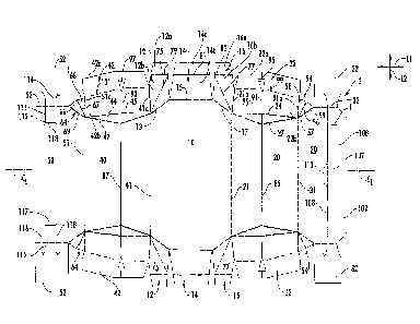
the bottom panel
10. Accordingly, each of the tear lines 943 includes a first curved portion
945a extending in
the second top panel 50 from an end of the oblique fold line 69 to the second
side panel 840,
a second curved portion 945b extending from an edge of the bottom end flap 812
and in the
bottom panel 10 to the second side panel 840, and a generally longitudinal
portion 945c
extending from an end of the first curved portion 945a to an end of the second
curved portion
945b. An opening feature 947 can be formed in the second side panel 840
adjacent the
longitudinal portion 945c of the tear line 943. The opening feature 947 can
help initiate
tearing of the tear line 943 to at least partially remove the dispenser panel
941. In one
embodiment, the fold line 79 and/or the fold line 101 in the respective end
flaps 812, 842 can
be tear lines. The dispenser panels 941, tear lines 943, and/or dispensers 808
could be
otherwise shaped, arranged, positioned, and/or configured without departing
from the
disclosure. Further one or both of the dispenser 808 and/or dispenser panels
941 could be
omitted without departing from the disclosure.
[00641 As
shown in Figs. 24 and 25, the blank 803 can be erected into an open-ended
sleeve 921 (Fig. 24), the containers C can be loaded into the sleeve (e.g., in
nested
-17-
CA 02911328 2015-10-30
WO 2014/190267
PCT/US2014/039351
arrangement N13), and the ends 871, 873 can be closed in a similar manner as
in the first and
fifth embodiments. Accordingly, as shown in Figs. 26 and 27, the closed ends
871, 873 of the
carton 805 can have a central portion 931 that is generally perpendicular to
the side panels
820, 840 and two oblique portions 933, 935 that are oblique with respect to
the side panels
820, 840 and the central portion 931. In one embodiment, the central portion
931 of the
carton 805 has a width D1 near the bottom of the carton 805 that is less than
the width D2 of
the central portion near the top of the carton. As shown in Fig. 26, the
distance D1 can be the
width of the central bottom end flap 814 and the distance D2 can be the
maximum width of
the overlapped top end flaps 32, 52.
[0065] Fig.
27 shows the carton 805 with one of the dispenser panels 941 of the dispenser
808 removed to form a dispenser opening 949 at one end 871 of the carton. The
carton 505
can be rotated 90 degrees from the carrying position (Fig. 26) to a dispensing
position (Fig.
27). In the dispensing position, the carton 805 is positioned with the first
side panel 820
positioned on a support surface S and the second side panel 840 positioned
opposite the
support surface. Removal of the dispenser panels 941 in the dispensing
position of Fig. 27
creates the dispenser openings 949, allows access to the containers C, and
helps prevent
unintended removal of containers. The row of containers C adjacent the second
side panel
840 has four containers and the middle row of containers with five containers
is retained in
the carton by the remaining portions of the end flaps 812, 814, 816, 822, 842,
852. 832 at the
closed end 871, 873. The blank 803 and/or carton 805 could be otherwise
shaped, arranged,
positioned, and/or configured without departing from the disclosure.
[0066] Figs.
28-33 illustrate a seventh embodiment of the disclosure that includes a carton
1005 formed from a blank 1003. The seventh embodiment is generally similar to
the first and
the sixth embodiments, except for variations noted and variations that will be
apparent to one
of ordinary skill in the art. Accordingly, similar or identical features of
the embodiments
have been given like or similar reference numbers. In the seventh embodiment,
the blank
1003 and the carton 1005 are configured to contain nine containers in the form
of 12-ounce
beverage cans C arranged in two layers: a bottom layer having five containers
and a top layer
having four containers. The two layers of containers are arranged so that the
ends 1071, 1073
of the carton 1005 are angled inwardly from the bottom of the carton 1005 to
the top of the
carton. The containers C could be otherwise shaped, arranged, positioned,
and/or configured
without departing from the disclosure.
-18-
CA 02911328 2015-10-30
WO 2014/190267
PCT/US2014/039351
[0067] In the
embodiment of Figs. 28-33, the blank 1003 comprises a bottom panel 1010, a
first side panel 1020 foldably connected to the bottom panel 1010 along a
lateral fold line
1021, a top panel 1030 foldably connected to the first side panel 1020 along a
lateral fold line
1031, and a second side panel 1040 foldably connected to the bottom panel 1010
along a
lateral fold line 1041. An adhesive or attachment flap 1050 is foldably
connected to the
second side panel 1040 along a lateral fold line 1051 for adhesive attachment
to the top panel
1030. In one embodiment, the blank 1003 has an upper side end flap 1022
foldably
connected to the first side panel 1020 at an oblique fold line 1023 and a
lower side end flap
1024 foldably connected to the first side panel 1020 at a longitudinal fold
line 1025.
Similarly, the blank 1003 has an upper side end flap 1042 foldably connected
to the second
side panel 1040 at an oblique fold line 1043 and a lower side end flap 1044
foldably
connected to the second side panel 1040 at a longitudinal fold line 1045. The
blank 1003
includes a top end flap 1032 foldably connected to the top panel 1030 at a
longitudinal fold
line 1033 and a bottom end flap 1014 foldably connected to the bottom panel
1010 at a
longitudinal fold line 1015. The end flaps 1014, 1022, 1024, 1032, 1042, 1044
can be
overlapped with respect to one another to at least partially close the first
end 1071 of the
carton. Additionally, the second end of the blank 1003 includes respective end
flaps 1014,
1022, 1024, 1032, 1042, 1044 that close the second end 1073 of the carton 1005
that are
identical to the end flaps for closing the first end 1071 of the carton.
Alternatively, the ends
1071, 1073 could be different from one another The blank 1003 could be
otherwise shaped,
arranged, positioned, and/or configured without departing from the disclosure,
[0068] As
shown in Fig. 28, each of the side panels 1020, 1040 includes a respective
oblique edge 1013, 1017 extending from respective ends of the longitudinal
fold line 1015 to
the respective longitudinal fold line 1025, 1045. The bottom end flap 1014
includes an outer
portion 1014a foldably connected to a base portion 1014b along a longitudinal
fold line 1081.
In the illustrated embodiment, the base portion 1014b is for being positioned
to extend
obliquely from the bottom panel 1010 along the oblique edges 1013, 1017 when
the carton
1005 is erected.
[0069] In the
embodiment of Figs. 28-33, the carton 605 includes two dispenser patterns
1006, each including a dispenser panel 1141 defined by a respective tear line
1143 in the
blank 1003 for forming a dispenser 1008 at each end 1071, 1073 of the carton
1005 (Figs. 29
and 30). In one embodiment, each dispenser panel 1141 includes portions of the
first side
-19-
CA 02911328 2015-10-30
WO 2014/190267
PCT/US2014/039351
panel 1020, the top panel 1030, the second side panel 1040, the attachment
flap 1050, the top
end flap 1032, and the upper side end flaps 1022,1042. As shown in Fig. 28,
the tear line
1143 can include a first curved portion 1145a extending in the first side
panel 1020 from an
end of the oblique fold line 1023 to the top panel 1030, a second curved
portion 1145b
extending in the second side panel 1040 to the attachment flap 1050, a first
longitudinal
portion 1145c extending from the end of the first curved portion 1145a to an
edge of the top
panel 1030, and a second longitudinal portion 1145d extending from the end of
the second
curved portion 1145b to an edge of the attachment flap 1050. When the carton
1005 is
erected, the first longitudinal portion 1145c can at least partially overlap
the second
longitudinal portion 1145d. In one embodiment, each of the top end flaps 1032
can include
an outer portion 1032a that is separable from a base portion 1032b along a
third longitudinal
portion 1045e of the tear line 1143. An access feature 1147 can be formed in
the top panel
1030 adjacent the first longitudinal portion 1145c of the tear line 1143 to
help initiate tearing
of the tear line 1143 when actuating the dispenser 1008. The dispenser panels
1141, tear lines
1143, or dispensers 1008 could be otherwise shaped, arranged, and/or
configured without
departing from the disclosure. Further, one or both of the dispensers 1008
and/or dispenser
panels 1141 could be omitted without departing from the disclosure.
[0070] In one
embodiment, the carton 1005 includes a handle 1105 formed in the top panel
1030 for grasping and carrying the carton 1005. The handle 1105 can include a
handle panel
1107 foldably connected to the top panel 1030 along a longitudinal fold line
1108. The
handle 1105 could be omitted or could be otherwise shaped, arranged,
positioned, and/or
configured without departing from the disclosure.
[0071] In one
embodiment, the beverage cans C have respective ends E and cylindrical
sides Si extending between the ends (e.g., Figs. 31-33). In the seventh
embodiment, the
containers C are positioned and arranged so that the sides Si of the
containers in the top row
or layer are positioned adjacent or in contact with the top panel 1030, and
the sides of the
bottom row of containers are positioned adjacent or in contact with the bottom
panel 1010.
The ends E of the containers are adjacent or in contact with one of the first
side panel 1020
and the second side panel 1040.
[0072] The
carton 1005 is formed in a similar manner as the cartons in the previous
embodiments. For example, an open-ended sleeve (not shown) can be formed by
folding the
panels 1010, 1020, 1030, 1040, 1050 around an interior of the sleeve and
adhering the
-20-
CA 02911328 2015-10-30
WO 2014/190267
PCT/US2014/039351
attachment flap 1050 to an interior surface of the top panel 1030. The ends
1071, 1073 of the
carton 1005 can be closed by folding the upper side end flaps 1022, 1042 and
the lower side
end flaps 1024, 1044 over the respective ends, upwardly folding the bottom end
flaps 1014,
and downwardly folding the top end flaps 1032 to overlap the respective side
end flaps 1022,
1042, 1024, 1044 at the respective ends. In one embodiment, the bottom end
flap 1014 can
be folded over the end of the carton so that the base portion 1014b is oblique
with respect to
the bottom panel 1010 and aligned with the oblique edges 1013, 1017. The outer
portion
1014a of the bottom end flap 1014 can overlap the lower side end flaps 1024,
1044, and the
portion 1014a and the flaps 1024, 1044 can be generally perpendicular to the
side panels
1020, 1040, the bottom panel 1010 and the top panel 1030. The base portion
1032b of the top
end flap 1032 can overlap the upper side end flaps 1022, 1042 and the base
portion 1032b and
the upper side end flaps 1022. 1042 can extend obliquely with respect to the
top panel 1030
and can be generally aligned with the oblique fold lines 1023, 1043. The outer
portion 1032a
of the top end flap 1032 can overlap the outer portion 1014a of the bottom end
flap 1014
and/or the lower side end flaps 1022, 1042. One or more of the end flaps 1014,
1022, 1024,
1032, 1042, 1044 can be secured together with adhesive such as glue. The
erected carton
1005 is shown in Figs. 29 and 30.
[0073] Either
or both of the dispensers 1008 can be activated as shown in Figs. 31-33 to at
least partially remove the respective dispenser panel 1141 from the carton
1005 and create a
respective dispenser opening 1149 for accessing the containers C at a
respective end 1071,
1073 of the carton. The dispenser 1008 at the first end 1071, for example, can
be actuated by
initiating tearing of the tear line 1143 at the access feature 1147, tearing
the tear line along the
longitudinal portions 1145c, 1145d, and tearing the tear line 1143 along the
curved
portions1145a, 1145b in the side panels 1020, 1040 as the dispenser panel 1141
is pivoted
away from the remainder of the carton 1005 along the longitudinal portion
1145e of the tear
line 1143 in the top end flap 1032. As shown in Fig. 31-33, when the dispenser
panel 1141 is
partially or completely removed to create the dispenser opening 1149, the
carton 1005
includes a retention portion 1151 at the bottom of the respective end 1071,
1073 of the carton
to retain the lower layer of containers C at the end of the carton. In one
embodiment, the
retention portion 1151 includes the lower side end flaps 1024, 1044, the
bottom end flap
1014, and the distal or outer portion 1032a of the top end flap 1032. As shown
in Figs. 32
and 33, the dispenser panel 1141 can be completely removed from the remainder
of the carton
1005 by further tearing the tear line 1143 along the longitudinal portion
1145e. The retention
-21-
CA 02911328 2015-10-30
WO 2014/190267
PCT/US2014/039351
portion 1151 extends across the width of the ends 1071, 1073 of the carton and
has a height to
retain the end container of at least the lower layer of containers C when the
dispenser panel
1141 is removed. The retention portion 1151 could be otherwise shaped,
arranged,
positioned, and/or configured without departing from the disclosure. For
example, the
retention portion 1151 could extend across less than the entire width of the
ends 1071, 1073
of the carton, or the retention portion could extend upward from the bottom
panel 1010 a
sufficient height to at least partially contact and retain the end container C
in the top layer of
the carton 1005.
[0074] The
blank 1003 and/or carton 1005 could be otherwise shaped, arranged, and/or
configured without departing from the disclosure.
[0075] Fig.
34 illustrates an eighth embodiment of the disclosure that includes a carton
1205 formed from a blank (not shown). The eighth embodiment is generally
similar to the
sixth embodiment and/or the seventh embodiment, except for variations noted
and variations
that will be apparent to one of ordinary skill in the art. Accordingly,
similar or identical
features of the embodiments have been given like or similar reference numbers.
In the eighth
embodiment, the carton 1205 is configured to contain ten bottles B in a single
layer in a
nested arrangement having two outer rows of three bottles per row and one
inner row of four
bottles. In one embodiment, the bottles B can be arranged similarly to the
nested arrangement
N4 in Fig. 35 except with only one inner row. The three layers of containers
are arranged so
that the ends are closed in a similar manner as the first embodiment to form a
central portion
1331 and two oblique portions 1333, 1335 at each end 1271, 1273 of the carton
1205. The
containers B could be otherwise shaped, arranged, positioned, and/or
configured without
departing from the disclosure.
[0076] As
shown in Fig. 34, the carton 1205 includes a dispenser 1208 that is similar to
one
of the dispensers 1008 of the seventh embodiment or one of the dispensers 806
of the sixth
embodiment. The dispenser 1208 includes a dispenser panel 1341 defined by a
tear line
(already torn as shown in Fig. 34) with curved portions in the bottom panel
1210 and the top
panel 1230 and oblique portions in the side panel 1240. When the dispenser
1208 is actuated
as shown in Fig. 34, a dispenser opening 1349 is formed in the first end 1271
of the carton, in
the side panel 1240, in the bottom panel 1210, and in the top panel 1230. The
carton 1205,
including the ends 1271, 1273 and/or the dispenser 1208 could be otherwise
shaped,
arranged, positioned, and/or configured without departing from the disclosure.
-22-
CA 02911328 2015-10-30
WO 2014/190267
PCT/US2014/039351
[0077] Any of
the features of the various embodiments of the disclosure can be combined
with, replaced by, or otherwise configured with other features of other
embodiments of the
disclosure without departing from the scope of this disclosure. Further, it is
noted that the
nesting arrangements and/or the features of the blanks and cartons of the
various
embodiments can be incorporated into a carton or blank having any carton style
or panel
configuration. The carton styles and panel configurations described above are
included by
way of example.
[0078] The
blanks according to any of the embodiments of the present disclosure can be,
for example, formed from coated paperboard and similar materials. For example,
the interior
and/or exterior sides of the blank can be coated with a clay coating. The clay
coating may
then be printed over with product, advertising, price coding, and other
information or images.
The blank may then be coated with a varnish to protect any information printed
on the blank.
The blank may also be coated with, for example, a moisture barrier layer, on
either or both
sides of the blank. In accordance with the above-described embodiments, the
blank may be
constructed of paperboard of a caliper such that it is heavier and more rigid
than ordinary
paper. The blank can also be constructed of other materials, such as
cardboard, hard paper, or
any other material having properties suitable for enabling the carton to
function at least
generally as described herein. The blank can also be laminated or coated with
one or more
sheet-like materials at selected panels or panel sections.
[0079] In
accordance with the above-described embodiments of the present disclosure, a
fold line can be any substantially linear, although not necessarily straight,
form of weakening
that facilitates folding therealong. More specifically, but not for the
purpose of narrowing the
scope of the present disclosure, fold lines include: a score line, such as
lines formed with a
blunt scoring knife, or the like, which creates a crushed portion in the
material along the
desired line of weakness; a cut that extends partially into a material along
the desired line of
weakness, and/or a series of cuts that extend partially into and/or completely
through the
material along the desired line of weakness; and various combinations of these
features.
[0080] As an
example, a tear line can include: a slit that extends partially into the
material
along the desired line of weakness, and/or a series of spaced apart slits that
extend partially
into and/or completely through the material along the desired line of
weakness, or various
combinations of these features. As a more specific example, one type tear line
is in the form
of a series of spaced apart slits that extend completely through the material,
with adjacent slits
-23-
CA 02911328 2015-10-30
WO 2014/190267
PCT/US2014/039351
being spaced apart slightly so that a nick (e.g., a small somewhat bridging-
like piece of the
material) is defined between the adjacent slits for typically temporarily
connecting the
material across the tear line. The nicks are broken during tearing along the
tear line. The
nicks typically are a relatively small percentage of the tear line, and
alternatively the nicks can
be omitted from or torn in a tear line such that the tear line is a continuous
cut line. That is, it
is within the scope of the present disclosure for each of the tear lines to be
replaced with a
continuous slit, or the like. For example, a cut line can be a continuous slit
or could be wider
than a slit without departing from the present disclosure.
[0081] The
above embodiments may be described as having one or more panels adhered
together by glue during erection of the carton embodiments. The term "glue" is
intended to
encompass all manner of adhesives commonly used to secure carton panels in
place.
[0082] The
foregoing description of the disclosure illustrates and describes various
exemplary embodiments. Various additions, modifications, changes, etc., could
be made to
the exemplary embodiments without departing from the spirit and scope of the
disclosure. It
is intended that all matter contained in the above description or shown in the
accompanying
drawings shall be interpreted as illustrative and not in a limiting sense.
Additionally, the
disclosure shows and describes only selected embodiments of the disclosure,
but the
disclosure is capable of use in various other combinations, modifications, and
environments
and is capable of changes or modifications within the scope of the inventive
concept as
expressed herein, commensurate with the above teachings, and/or within the
skill or
knowledge of the relevant art. Furthermore, certain features and
characteristics of each
embodiment may be selectively interchanged and applied to other illustrated
and non-
illustrated embodiments of the disclosure.
-24-