Note: Descriptions are shown in the official language in which they were submitted.
1
PNEUMATIC TIRE
CROSS-REFERENCE TO RELATED APPLICATION
[0001] This application claims priority of Japanese Patent Application
No. 2014-233821.
BACKGROUND OF THE INVENTION
[0002] The present invention relates to a pneumatic tire.
[0003] Heretofore, there is publicly known a conventional pneumatic
tire having a projection formed on at least one-side groove wall of each
width direction groove of a tread center part (e.g., refer to JP 2012-
148678 A).
[0004] However, the above projection is only effective as anti-stone
biting performance, namely the performance which can prevent pebbles
and the like on a road surface from getting caught in a groove portion.
When travelling on a muddy area with such tires mounted, mud and
the like penetrate into the groove portion so that they may get stuck.
In this case, traction performance of the tires deteriorates, or side-
slipping occurs when cornering.
SUMMARY OF INVENTION
TECHNICAL PROBLEM
[0005] It is an object of the present invention to provide a pneumatic
tire which can exhibit excellent mud removal performance.
SOLUTION TO PROBLEM
[0006] As means for solving the above problem, the present invention
provides a pneumatic tire comprising, on a tread portion, a plurality of
CA 2911606 2018-03-13
2
blocks formed by a plurality of main grooves annularly continuously
extending in a tire circumferential direction, and a plurality of
transverse grooves extending in a tire width direction, intersecting these
main grooves, wherein each block has a side surface defined by a
respective transverse groove, the side surface defining a corner region
of the respective block, each block has a projection projecting from the
side surface at the corner region and into the transverse groove, and
the corner region defined by the side surface of each block is a portion
of the block where the deformation amount becomes greater than that
of other portions of the respective block when the block is elastically
deformed by contacting the ground.
[0007] With
this construction, the block contacting the ground is
elastically deformed, and its shape changes particularly at the corner
region thereof. The projection is formed at the corner region, and
greatly displaced according to its elastic deformation. Therefore, even
if the tires travel on a muddy place, and mud and the like penetrate
into the transverse groove, they are effectively scraped out by the
projection. That is, the tires are excellent in mud removal performance.
[0008] It is preferred that a lower end of the projection is located above
the bottom of the transverse groove, and an upper end thereof is located
within a range of a half or more of a depth dimension from the bottom
of the transverse groove.
[0009] This construction makes the lower end portion of the projection
less likely to hamper elastic deformation of the block, so that
displacement of the projection accompanying the elastic deformation of
the block is hardly suppressed. Also, locating the upper end of the
projection above in the transverse groove can enhance mud removal
CA 2911606 2018-03-13
3
performance.
[0010] It is preferred that a projection range of the projection on the
side surface is set so that a ratio R1 of a vertical length dimension of
the projection to a depth dimension of the transverse groove satisfies
30% -___- R1 80%.
[0011] This construction can further increase a movable volume
caused by the displacement of the projection accompanying the elastic
deformation of the block, thus making it possible to further enhance
mud removal performance.
[0012] It is preferred that a width dimension of the projection
gradually reduces toward the bottom of the transverse groove.
[0013] With this construction, even if a force is exerted on the
projection itself, cracks and the like hardly occur and thus good mud
removal performance can be maintained over a long period of time.
[0014] It is preferred that a ratio R2 of a projection dimension of the
projection at a maximum projection position to a width dimension of
the transverse groove at the maximum projection position of the
projection satisfies 20% R2 60%, wherein the maximum projection
position is where the projection projects the most from the side surface
of the block.
[0015] With this construction, the displacement of the projection
accompanying the elastic deformation of the block can be made within
a range suitable for mud removal.
[0016] It is preferred that each block comprises a parallelogram shape
with a projecting portion which projects from a side of the parallelogram
and which has a smaller width dimension than the side of the
parallelogram from which it projects, and wherein the side surface
CA 2911606 2018-03-13
4
defining the corner region of the block is a side surface of the projecting
portion.
[0017] With this construction, the deformation amount of the corner
region can be sufficiently increased by the elastic deformation of the
block. Therefore, it becomes possible to secure the desired mud
removal performance by increasing the displacement of the projection.
[0018]
According to the present invention, since the projection is
formed on the side surface, which forms the transverse groove, at the
corner region of the block, the displacement of the projection can be
increased by the elastic deformation of the block due to its contacting
the ground. Therefore, the tire of the present invention is excellent in
mud removal performance. Even if mud and the like penetrate into the
transverse groove, they can be efficiently removed by the projections.
BRIEF DESCRIPTION OF THE DRAWINGS
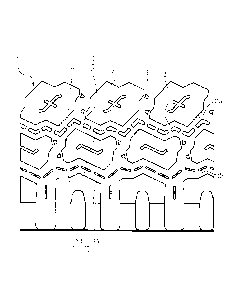
[0019]
Fig. 1 is a partial development view of a tread portion according
to the present embodiment;
Fig. 2 is an enlarged view of center blocks of Fig. 1;
Fig. 3 is an enlarged view of mediate blocks of Fig. 1; and
Fig. 4 is a partial cross-sectional view of a center block and a
mediate block of Fig. 1.
DETAILED DESCRIPTION OF THE PREFERRED EMBODIMENTS
[0020] The
present invention will hereinafter be described with
reference to the attached drawings. The following description is
essentially a mere illustration, and is not intended to limit the present
CA 2911606 2018-03-13
5
invention, its application, or its use. The drawings are schematic, and
ratios of the respective dimensions are different from actual ones.
[0021] Fig. 1 shows a partial development view of a tread portion 1 of
the present embodiment. In the tread portion 1, a plurality of main
grooves 2 annularly continuously extending in a tire circumferential
direction, and a plurality of transverse grooves 3 extending in a tire
width direction, intersecting these main grooves 2 are formed. Herein,
the main grooves 2 each of which has a zigzag-shape, and which are
four in number (only a first groove 2a and a second groove 2b on one
side are shown, and the other two are omitted) are formed at
predetermined intervals in the tire width direction. The transverse
grooves 3 are each provided slantly with respect to a straight line
extending in the tire width direction. A plurality of blocks 4 are formed
by the main grooves 2 and the transverse grooves 3.
[0022] The blocks 4 consist of center blocks 5 arranged in the tire
circumferential direction at the center of the tire-width direction,
mediated blocks 6 arranged on both sides thereof (those arranged on
one side are omitted), and side blocks 7 arranged on further outsides
thereof (those arranged on one side are omitted).
[0023] As shown in Fig. 2, when the tread portion 1 is seen in plan
view, each center block 5 is formed in a shape obtained by cutting off
four corners of a parallelogram surrounded by a pair of mutually
parallel long sides 8 and a pair of mutually parallel short sides 9. Of
the two pairs of diagonally positioned corners, at one pair of corners, a
first cutoff side 10 parallel to each short side 9, and a second cutoff side
11 more slanted than a straight line parallel to each long side 8, which
form each corner, are formed (an area cut off to the first cutoff line 10
CA 2911606 2018-03-13
6
and the second cutoff line 11 from the original shape of the
parallelogram will hereinafter be referred to as a first cutoff portion 12).
The other pair of corners is cut off so that three zigzag-shaped sides (a
third cutoff side 13, a fourth cutoff side 14 and a fifth cutoff side 15)
are obtained (an area cut off to these three sides from the original shape
of the parallelogram will hereinafter be referred to as a second cutoff
portion 16).
[0024] In the center block 5, a pair of diagonally positioned projecting
portions 17, each of which is formed by the first cutoff portion 12 and
the second cutoff portion 16, are formed. That is, each first projecting
portion 17 having a narrower width than other portions is formed by
the second cutoff side 11, the short side 9, the third cutoff side 13, the
fourth cutoff side 14, and the fifth cutoff side 15.
[0025] As shown in Fig. 4, a side surface 18 of the center block 5 is
formed of an inclined surface gradually projecting toward inside of the
groove as it goes down to the bottom of the main groove 2 and the
transverse groove 3. An upper end portion of the side surface 18 is
formed in a convex shape having an arc shape in cross section so as to
smoothly reach the side surface 18 from a surface of the center block
5. A lower end portion of the side surface 18 is formed in a concave
shape having an arc shape in cross section so as to smoothly reach the
bottom of the groove from the side surface 18. A first projection 19 is
formed on the side surface 18 of the center block 5.
[0026] As shown in Fig. 2, of the side surfaces 18 forming corners of
the center block 5 (the first projecting portion 17), the first projection
19 is formed at a corner region of the side surfaces 18 forming the
transverse groove 3. The corner region herein means the side surfaces
CA 2911606 2018-03-13
7
18 of the first projecting portion 17, which is a portion where the
deformation amount becomes greater than that of other portions when
the center block 5 is elastically deformed by contacting the ground.
Specifically, the first projection 19 is formed at a region corresponding
to a boundary portion of the third cutoff side 13 and the fourth cutoff
side 14 of the first projecting portion 17, namely, formed straddling both
the side surfaces 18 corresponding to the third cutoff side 13 and the
fourth cutoff side 14. In this manner, since the first projection 19 is
formed on the first projecting portion 17 having a large deformation
amount, it is possible to increase the displacement of the first projection
19.
[0027] A lower end of the first projection 19 is located above the bottom
of the transverse groove 3. Therefore, when the center block 5 contacts
the ground and is elastically deformed, the first projection 19 does not
hamper the deformation thereof. A predetermined region from the lower
end to an upper side (lower end portion) is formed of a concave (R-
shape) curved surface having an arc shape in cross section so as to be
smoothly continuous with respect to the side surface 18. A radius of
curvature R of the lower end portion is set so that cracks do not occur
due to stress concentration when the center block 5 contacts the
ground and is elastically deformed.
[0028] On the other hand, an upper end of the first projection 19 is
located above, beyond a position of a half of a groove depth from the
bottom of the transverse groove 3. Therefore, the displacement of the
first projection 19 becomes sufficient due to elastic deformation of the
center block 5. A predetermined region from the upper end of the first
projection 19 to a lower side (upper end portion) is formed of a concave
CA 2911606 2018-03-13
8
(R-shape) curved surface having an arc shape in cross section so as to
be smoothly continuous with respect to the side surface 18, similarly to
the lower end portion.
[0029] In this manner, since the upper end position and lower end
position of the first projection 19 are set, it is sufficiently deformed
accompanying the elastic deformation of the center block 5. Therefore,
even if mud and the like get stuck in the transverse groove 3, they can
be reliably removed.
[0030] A vertical length h of the first projection 19 is set so that a ratio
R1 of the vertical length h to a depth W of the transverse groove 3
(=h/W) satisfies 30% R1 If the
length of the first projection
19 is less than 30%, a displacement region of the first projection 19
accompanying the elastic deformation of the center block 5 is narrow,
so that sufficient mud removal performance cannot be exhibited. On
the other hand, if the length of the first projection 19 exceeds 80%, a
sufficient distance between the lower end position and the bottom of
the groove cannot be secured. Therefore, the R dimension of the curved
surface formed at the lower end portion of the first projection 19
becomes small, so that cracks may occur due to stress concentration
when the center block 5 is elastically deformed.
[0031] A width dimension of the first projection 19 is set so as to be
gradually reduced as it projects from both the side surfaces 18. The
width dimension of the first projection 19 at a maximum projection
position where the first projection 19 projects most is set as follows:
That is, a ratio R2 of a projection dimension p of the first projection 19
to a width dimension W of the transverse groove 3 at a maximum
projection position of the projection from the side surface 18 of the block
CA 2911606 2018-03-13
9
4 (=p/W) satisfies 20% R2 60%. If the projection ratio of the first
projection 19 is less than 20%, the displacement of the first projection
19 is insufficient, so that the desired mud removal performance cannot
be obtained. On the other hand, if the projection ratio of the first
projection 19 exceeds 60%, the inside of the transverse groove 3 is
clogged with the first projections 19, so that the desired mud removal
performance cannot be obtained.
[0032] A first closed groove 20 is formed on a central portion of the
surface of the center block 5. The first closed groove 20 consists of a
first groove 21 extending on a center line parallel to both the long sides
8 of the center block 5, and a second groove 22 extending on a center
line parallel to both the short sides 9 thereof. The first groove 21 is
longer than the second groove 22, and both of them are formed to have
the same width and depth. The first groove 21 and the second groove
22 are at right angles to each other at the center, and an intersection
of the center lines of the respective grooves coincides with a gravity
center position of the center block 5. Furthermore, both ends of the
first groove 21 and the second groove 22 are terminated (closed) within
the surface of the center block 5 so that they are not open to side
surfaces 18 of the center block 5. This will secure a sufficient distance
from each position of the first closed groove 20 to an outer edge of the
center block 5. Both ends of the first groove 21 are bent conforming to
the shape of the first projection 17 formed by the first cutoff portion 12
and the second cutoff portion 16.
[0033] As
shown in Fig. 3, each mediated block 6 has a roughly
rectangular shape, and a half thereof consists of a first side 23, a second
side 24, a third side 25, a fourth side 26, a fifth side 27, a sixth side 28,
CA 2911606 2018-03-13
10
and a seventh side 29. The other half are formed at point-symmetrical
positions around the gravity center position. Second projecting
portions 30 are formed at a pair of diagonally positioned corners. Each
second projecting portion 30 consists of the second to sixth sides 24-
28. As shown in Fig. 1, the second side 24 and the third side 25 are
parallel to the first cutoff side 10 and the second cutoff side 11 of the
center block 5, respectively. A second closed groove 31 is formed at a
central portion of the mediate block 6. The second closed groove 31 is
arranged on a center line along the first side 23, and its both ends are
respectively bent in their projection directions.
[0034] As
shown in Fig. 4, similarly to the center block 5, a side
surface 18 of the mediate block 6 is formed of an inclined surface
gradually projecting toward inside of the groove as it goes down to the
bottom of the main groove 2 and the transverse groove 3. An upper end
portion of the side surface 18 is formed in a convex shape having an arc
shape in cross section so as to smoothly reach the side surface 18 from
a surface of the mediate block 6. A lower end portion of the side surface
18 is formed in a concave shape having an arc shape in cross section
so as to smoothly reach the bottom of the groove from the side surface
18. A second projection 32 is formed on the side surface 18 of the
mediate block 6.
[0035] That is, the second projections 32 are formed respectively on
the fourth sides 26 of the second projecting portions 30, which are
formed at diagonal positions of the mediate block 6. Each second
projection 32 projects toward the sixth side of each mediate block 6
adjacently arranged through the transverse groove 3. Similarly to the
first projection 19, a lower end position, upper end position, vertical
CA 2911606 2018-03-13
11
length, width dimension, projection dimension from the side surface 18
and the like of the second projection 32 are determined.
[0036] A plurality of protrusions 33 are formed on a center line of the
main groove 2. First protrusions 34 each of which has a width
dimension of about a half of the width of the groove are formed on a
first main groove 5a between the center block 5 and the mediate block
6. Some of the first protrusions 34 have a straight line shape formed
on a straight line portion of the first main groove 5a, and others have a
bent shape formed on a bent portion thereof. Second protrusions 35
each of which has a width dimension of about one tenth of the width of
the groove are formed on a second main groove 5b between the mediate
block 6 and the side block 7. All the second protrusions 35 have a
straight line shape. These protrusions 33 have a role of preventing
foreign materials such as stones from reaching and damaging the
bottom of the groove, and of removing them from the main groove 2.
[0037] Next,
operation of the pneumatic tire having the above
construction will be described.
[0038] When the pneumatic tires having the above construction are
mounted on a vehicle, and it travels on a bad road such as a muddy
area, mud and the like penetrate into the main groove 2 and the
transverse groove 3. The main groove 2 extends in a tire circumferential
direction, so that mud and the like are easily removed to the outside.
On the other hand, the transverse groove 3 extends in a tire width
direction, so that the penetrated mud and the like are hardly removed
to the outside if they are left as they are. The center block 5 and the
mediate block 6 are elastically deformed to change their shapes when
they contact the ground. In the center block 5 and the mediate block
CA 2911606 2018-03-13
12
6, the first projecting portion 17 and the second projecting portion 30,
which have a largest deformation amount, are provided with the first
projection 19 and the second projection 32, respectively. For that
reason, the displacements of the first projection 19 and the second
projection 20 can be increased sufficiently. Therefore, even if mud and
the like penetrate into the transverse groove 3, they can be reliably
removed by the first projection 19 and the second projection 20 having
large displacements.
[0039] The
present invention is not limited to the construction
described in the above embodiment, and various modifications can be
made.
[0040] In the above embodiment, although the first projection 19 is
formed straddling both the side surfaces 18 corresponding to the third
cutoff side 13 and the fourth cutoff side 14 forming a part of the first
projecting portion 17 of the center block 5, only the side surface 18
corresponding to the third cutoff side 13, or the side surface 18
corresponding to the fourth cutoff side 14 may be provided with the first
projection 19. Further, although the second projection 32 is formed on
the side surface 18 corresponding to the fourth side 26 forming a part
of the second projecting portion 30 of the mediate block 6, the second
projection may be formed on the side surface 18 corresponding to the
fifth side 27. Also, the shape of the block 4 is not limited to the above.
Therefore, the block 4 may be of any shape that can be adopted as long
as the projection is formed on the side surface 18, which forms the
transverse groove 3, at the corner region of the block 4.
CA 2911606 2018-03-13