Note: Descriptions are shown in the official language in which they were submitted.
FUEL CELL SYSTEM FOR ESTIMATING FLOW RATE OF FUEL GAS
FIELD OF THE INVENTION
[0001] The present invention relates to a fuel cell system.
BACKGROUND
[0002] There is known a fuel cell system that includes: a gas-liquid separator
storing and
separating water from a fuel gas partially discharged from a fuel cell; and a
discharge valve
connected to the gas-liquid separator and partially discharging the fuel gas
to the outside
together with the stored water in the gas-liquid separator. For example,
Japanese Unexamined
Patent Application Publication No. 2005-302708 describes technology for
estimating a
discharge amount of the fuel gas by opening the discharge valve. In some
cases, the discharge
valve herein includes a discharge outlet opened and closed by a valve body.
[0003] To finely estimate the discharge amount of the fuel gas, it is
preferable to finely
estimate a discharge flow rate of the fuel gas per unit time. The discharge
flow rate of the fuel
gas is finely estimated conceivably based on, for example, a differential
pressure between
upstream and downstream sides of the discharge valve during the opening period
of the
discharge valve. The discharge flow rate is estimated conceivably by use of
the detected
differential pressure on the basis of, for example, the relationship between
the differential
pressure and the gas discharge flow rate that is defined beforehand through
experimental
results.
[0004] The estimation of the gas discharge flow rate based only on the
differential pressure
might, however, degrade the estimation accuracy. For example, although the
fuel gas is
partially discharged after the stored water is discharged by opening the
discharge valve, water
generated by electric generation of the fuel cell might be discharged as the
stored water from
the gas-liquid separator through the discharge outlet of the discharge valve
to the outside even
during the discharge of the fuel gas. At this time, the stored water and the
fuel gas are
conceivably discharged from the discharge outlet at the same time. A
percentage of an area,
through which the fuel gas substantially flows, to a cross sectional area of
the discharge outlet
1
CA 2911767 2017-06-29
CA 02911767 2015-11-10
is herein by subtracting a percentage of the stored water to the cross
sectional area of the
discharge outlet therefrom. The percentage of the stored water to the cross
sectional area of
the discharge outlet varies with the amount of the stored water. Thus, the
percentage of the
area, through which the fuel gas substantially flows, to the cross sectional
area of the
discharge outlet varies. Therefore, if the gas discharge flow rate is
estimated based only on
the differential pressure without considering the percentage of the area,
through which the
fuel gas substantially flows, to the cross sectional area of the discharge
outlet, the estimation
accuracy of the gas discharge flow rate might deteriorate.
SUMMARY OF THE INVENTION
[0005] It is therefore an object of the present invention to provide a fuel
cell system that
suppresses deterioration in estimation accuracy of a discharge flow rate of a
fuel gas.
[0006] According to an aspect of the present invention, a fuel cell system
includes: a fuel
cell; a fuel supply source that supplies a fuel gas to the fuel cell; a supply
passage through
which the fuel gas supplied from the fuel supply source flows to the fuel
cell; a circulation
passage through which the fuel gas partially discharged from the fuel cell
flows to the supply
passage; a gas-liquid separator that is arranged in the circulation passage
and that stores and
separates water from the fuel gas partially discharged from the fuel cell; a
discharge passage
that is connected to the gas-liquid separator, discharges stored water in the
gas-liquid
separator to an outside, and partially discharges the fuel gas partially
discharged from the fuel
cell to the outside; a discharge valve that is arranged in the discharge
passage; a differential
pressure detecting portion that detects a differential pressure between a
downstream side of
the discharge valve and one of the supply passage, the circulation passage,
the gas-liquid
separator, and an upstream side of the discharge valve in the discharge
passage; and a control
unit that estimates a flow rate of the fuel gas partially discharged from the
fuel cell partially
discharged by opening the discharge valve, wherein the discharge valve
includes: a discharge
outlet through which the stored water and the fuel gas partially discharged
from the fuel cell
partially flows; and a valve body that opens and closes the discharge outlet,
and the control
unit estimates the flow rate of the fuel gas, based on the differential
pressure while the
2
CA 02911767 2015-11-10
discharge valve is opened, and based on a percentage of the fuel gas to a
cross sectional area
of the discharge outlet, except for a percentage of the stored water to the
cross sectional area,
while the discharge valve is opened.
[0007] The control unit may estimate the percentage of the fuel gas based on a
current value
of thc fuel cell.
[0008] The control unit may estimate the flow rate based on composition of the
fuel gas.
[0009] According to another aspect of the present invention, a fuel cell
system includes: a
fuel cell; a fuel supply source that supplies a fuel gas to the fuel cell; a
supply passage through
which the fuel gas supplied from the fuel supply source flows to the fuel
cell; a gas-liquid
separator that stores and separates water from the fuel gas partially
discharged from the fuel
cell; a first discharge passage through which the fuel gas partially
discharged from the fuel
cell flows to the gas-liquid separator; a second discharge passage that is
connected to the
gas-liquid separator, discharges stored water in the gas-liquid separator to
an outside, and
partially discharges the fuel gas partially discharged from the fuel cell to
the outside; a
discharge valve that is arranged in the second discharge passage; a
differential pressure
detecting portion that detects a differential pressure between a downstream
side of the
discharge valve and one of the supply passage, the first discharge passage,
the gas-liquid
separator, and an upstream side of the discharge valve in the second discharge
passage; and a
control unit that estimates a flow rate of the fuel gas partially discharged
from the fuel cell
partially discharged by opening the discharge valve, wherein the fuel cell
system is an anode
non-circulation type in which the fuel gas partially discharged from the fuel
cell does not
return to the supply passage, the discharge valve includes: a discharge outlet
through which
the stored water and the fuel gas partially discharged from the fuel cell
partially flows; and a
valve body that opens and closes the discharge outlet, and the control unit
estimates the flow
rate of the fuel gas, based on the differential pressure while the discharge
valve is opened, and
based on a percentage of the fuel gas to a cross sectional area of the
discharge outlet, except
for a percentage of the stored water to the cross sectional area, while the
discharge valve is
opened.
3
CA 02911767 2015-11-10
EFFECT OF THE INVENTION
[0010] According to the present invention, it is possible to provide a fuel
cell system that
suppresses deterioration in estimation accuracy of a discharge flow rate of a
fuel gas.
BRIEF DESCRIPTION OF TIIE DRAWINGS
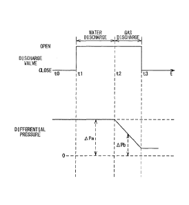
[0011] FIG. 1 is a schematic view of a fuel cell system;
FIG. 2 is a timing chart indicating operation of a discharge valve, and a
change in
difference in pressure between a circulation passage and a downstream side of
a discharge
valve in a discharge passage;
FIG. 3 is a flowchart of opening and closing control for the discharge valve
executed
by an ECU;
FIG. 4 is a map that defines a relationship between the differential pressure
and a
water discharge flow rate;
FIG 5 is a graph for describing a reference flow rate and a reference
differential
pressure;
FIG 6 is a map that defines a relationship between a required electric
generation
amount of a fuel cell and a target hydrogen partial pressure;
FIG. 7 is a sectional view of the discharge valve;
FIG. 8 is a sectional view of the discharge valve;
FIG. 9 is a sectional view of a discharge outlet after the water discharge is
determined
to be completed;
FIG. 10 is a sectional view of the discharge outlet after the water discharge
is
determined to be completed;
FIG 11 is a map that defines a relationship between a correction coefficient
Kc and a
current value of the fuel cell; and
FIG. 12 is a schematic view of a fuel cell system according to a variation.
DETAILED DESCRIPTION
[0012] In the following, a fuel cell system 1 (referred to as system)
according to the present
4
CA 02911767 2015-11-10
embodiment will be described with reference to drawings. The system 1 can be
applied to a
system installed in a vehicle. However, the system 1 may be applied to another
system.
FIG 1 is a schematic view of the system 1. The system 1 includes a fuel cell 2
as a power
supply. In the fuel cell 2, a electrolyte film such as a solid polymer
electrolyte membrane is
sandwiched between an anode and a cathode of catalyst electrodes (the
electrolyte film, the
anode, and the cathode are not illustrated). The anode is supplied with a fuel
gas containing
hydrogen, and the cathode is supplied with a oxidizing gas containing oxygen
such air, which
generates electricity.
[0013] A tank 3 is a fuel supply source supplying the fuel gas to the fuel
cell 2. An anode
inlet of the fuel cell 2 is connected to a supply passage 4 through which the
fuel gas supplied
from the tank 3 flows to the fuel cell 2. A regulating valve 6 is arranged in
the supply
passage 4. The regulating valve 6 reduces the pressure of the fuel gas
supplied from the
tank 3 to be a predetermined pressure, and then the fuel gas is supplied to
the fuel cell 2.
Also, an injector 10 is arranged on the downstream side of the regulating
valve 6 in the supply
passage 4. The injector 10 is an electromagnetic on-off valve. As for the on-
off valve, a
valve body is directly driven away from a valve seat by the electromagnetic
driving force in a
predetermined period, thereby regulating a gas flow rate and a gas pressure.
The injector 10
and the regulating valve 6 are controlled by an ECU (Electronic Control Unit)
20.
[0014] An anode outlet of the fuel cell 2 is connected to a circulation
passage 8 through
which the fuel gas (a fuel off-gas) partially discharged from the fuel cell 2
flows to the supply
passage 4. Specifically, the downstream end of the circulation passage 8 is
connected to the
supply passage 4. Also, the circulation passage 8 is provided with a
circulation pump 9 for
pressurizing and supplying the fuel gas partially discharged from the fuel
cell 2 to the supply
passage 4. Therefore, in this system 1, the fuel gas circulates through the
supply passage 4
and the circulation passage 8 during operation of the fuel cell 2.
[0015] A part of the circulation passage 8 is provided with a gas-liquid
separator 12 that
separates water from the fuel gas and has a storage tank 12a for storing the
separated water.
In the system 1, water generated by the electric generation of the fuel cell 2
leaks through the
electrolyte membrane from the cathode side to the anode side. The water moved
to the
5
CA 02911767 2015-11-10
anode side is discharged together with the fuel gas to the circulation passage
8, and then is
stored in the gas-liquid separator 12.
[0016] A bottom portion of the storage tank 12a of the gas-liquid separator 12
is connected
to a discharge passage 14 that discharges the stored water in the gas-liquid
separator 12 to the
outside and partially discharges the fuel gas partially discharged from the
fuel cell 2. The
downstream end of the discharge passage 14 is exposed to the outside air. A
discharge valve
16 is arranged in the discharge passage 14. The discharge valve 16 is usually
closed, but is
opened by the ECU 20 as needed. The discharge valve 16 is, for example, a shut-
off valve.
The discharge valve 16 is opened to discharge the water before the stored
water overflows
from the storage tank 12a, which can prevent the water from being supplied to
the fuel cell 2
through the circulation passage 8 and the supply passage 4.
[0017] A pressure sensor 21 that detects the pressure in the supply passage 4
is provided on
the downstream side of the injector 10 in the supply passage 4. The pressure
sensor 21
basically detects the pressure of the fuel gas to be supplied to the fuel cell
2. A pressure
sensor 22 that detects the pressure in the circulation passage 8 is provided
on the upstream
side of the gas-liquid separator 12 in the circulation passage 8. The pressure
sensor 22
basically detects the pressure of the fuel gas partially discharged from the
fuel cell 2 and
detects the pressure in the upstream side of the discharge valve 16. A
pressure sensor 23 that
detects the pressure in the downstream side of the discharge valve 16 in the
dischatge passage
14 is provided therein and that detects the pressure in the downstream side of
the discharge
valve 16. A detection value of the pressure sensor 23 indicates generally
atmospheric
pressure. The pressure sensors 21 to 23 are connected to the input side of the
ECU 20.
[0018] A load device 30 is connected to the fuel cell 2. The load device 30
measures an
electric characteristic of the fuel cell 2 and uses, for example, a potentio-
galvanostat of a
versatile electrochemical type. The load device 30 is electrically connected
to an anode side
separator and a cathode side separator of the fuel cell 2 through wirings. The
load device 30
measures a current flowing through the fuel cell 2 at the time of electric
generation thereof
and a load voltage (cell voltage) of the fuel cell 2. The load device 30 is an
example of a
current detecting portion detecting a current value.
6
CA 02911767 2015-11-10
[0019] The fuel cell 2 is connected to a passage that circulates a cooling
medium for cooling
the fuel cell 2, and a radiator 40 is provided on the passage. Water, air, or
the like can be
used as the cooling medium. A temperature sensor 24 that detects the
temperature of the
cooling medium is provided on the passage in an outlet side of the radiator
40. The
temperature sensor 24 is connected to the input side of the ECU 20.
[0020] The ECU 20 includes a microcomputer including a CPU (Central Processing
Unit), a
ROM (Read Only Memory), and a RAM (Random Access Memory). The ECU 20 is
electrically connected to each component of the system 1 and controls
operation of each
component on the basis of information sent therefrom. Also, the ECU 20 is an
example of a
control unit that executes control for estimating a discharge amount of the
fuel gas described
later in detail.
[0021] Additionally, a passage for supplying oxidation gas is connected to the
cathode inlet
of the fuel cell 2, and a passage for discharging an oxidation off-gas is
connected to the
cathode outlet, but they are omitted in FIG I.
[0022] As mentioned above, the opening of the discharge valve 16 permits the
discharge of
the stored water from the gas-liquid separator 12 to the outside. At this
time, the fuel gas is
partially discharged together with the stored water to the outside. It is
desirable herein that
the actual discharge amount of the fuel gas partially discharged from the
discharge valve 16 is
controlled to be the same as the target gas discharge amount. This is because,
if the actual
gas discharge amount is much larger than the target gas discharge amount, the
fuel gas might
be wasted and the fuel consumption might be degraded. In contrast, if the
actual gas
discharge amount is much smaller than the target gas discharge amount, for
example, if the
actual gas discharge amount is zero, the stored water might not be
sufficiently discharged.
Also, if the gas discharge amount is small, movement of nitrogen from the
cathode side to the
anode side due to the crossover might increase nitrogen concentration of the
fuel, which might
adversely influence the fuel consumption. Thus, this system 1 estimates the
discharge
amount of the fuel gas partially discharged during the opening of the
discharge valve 16, and
closes the discharge valve 16 when the estimated gas discharge amount reaches
the target gas
discharge amount.
7
CA 02911767 2015-11-10
[0023] Next, a description will be given of a change in pressure by operation
of the
discharge valve 16. FIG. 2 is a timing chart indicating the operation of the
discharge valve
16 and a change in the difference in pressure between the circulation passage
8 and the
downstream side of the discharge valve 16 in the discharge passage 14.
Additionally, FIG. 2
illustrate a case where the fuel gas is continuously supplied from the
injector 10 and where the
injector 10 is feedback-controlled such that the pressure in the supply
passage 4 detected by
the pressure sensor 21 is the same as a target pressure. The difference in
pressure between
the circulation passage 8 and the downstream side of the discharge valve 16 in
the discharge
passage 14 (hereinafter referred to as differential pressure) is detected
based on the output
values from the pressure sensors 22 and 23. In FIG. 2, the discharge valve 16
is closed at
time tO, the discharge valve 16 is opened at time tl, the discharge of the
stored water from the
gas-liquid is completed from time ti to time t2, and the fuel gas is partially
discharged from
time t2 to time t3. Also, for convenience of explanation, the differential
pressure during the
discharge of the stored water is referred to as the differential pressure APa,
and the differential
pressure during the discharge of the fuel gas is referred to as the
differential pressure APb.
[0024] As illustrated in FIG 2, the differential pressure APa does not change
immediately
after the discharge valve 16 is opened, but the differential pressure APb
decreases some time
after the discharge valve 16 is opened. In a period from time tO when the
discharge valve 16
is closed to time t2 when the water discharge is completed, the pressure in
the circulation
passage 8 slightly decreases in reality. However, this decrease amount is
negligible, so the
differential pressure APa does not substantially change. Further, the
differential pressure
APa from time tl to time t2 does not substantially change. This is because the
stored water
is discharged from time ti to time t2, but the fuel gas is not discharged.
[0025] When the discharge of the stored water is completed and the gas-liquid
separator 12
and the discharge passage 14 communicate with the atmosphere, the fuel gas is
partially
discharged through the discharge passage 14. As a result, the differential
pressure APb
decreases from time t2 to time t3. This is because the discharge of the fuel
gas decreases the
pressure in the supply passage 4 communicating with the circulation passage 8.
Also, when
it is determined that the estimated gas discharge amount by the estimation
method to be
8
CA 02911767 2015-11-10
described later reaches the target gas discharge amount, the discharge valve
16 is closed.
[0026] FIG. 3 is a flowchart of the opening and closing control for the
discharge valve 16
executed by the ECU 20. The ECU 20 determines whether or not the system 1 is
operated
(step Si). This is because the discharge process of the stored water is
executed when the
system 1 is operated. When the system 1 is operated, the ECU 20 executes
processes after
step Sl. When the system 1 is not operated, this control is finished.
[0027] Next, the ECU 20 determines whether or not open conditions of the
discharge valve
16 are satisfied (step S2). The open conditions are, for example, when a
predetermined
period elapses from the time when the discharge valve 16 is opened last, but
the present
invention is not limited to this. When the open conditions are not satisfied,
this control is
finished. When the open conditions of the discharge valve 16 are satisfied,
the ECU 20
opens the discharge valve 16 (step S3) and determines whether or not the water
discharge is
completed (step S4).
[0028] The determination whether or not the water discharge is completed is,
for example,
as follows. The ECU 20 calculates the stored water amount in the gas-liquid
separator 12
just before the discharge valve 16 is opened. For example, the ECU 20
calculates the stored
water amount in the gas-liquid separator 12 by calculating the amount of water
generated in
response to the electric generation of the fuel cell 2 from the time when the
water is
discharged last, on the basis of a relational equation, a map, or the like
associating the
generated water amount with the current of the fuel cell 2. The electric
generation amount of
the fuel cell 2 is calculated based on the current. Next, the ECU 20 estimates
the amount of
the water discharged from the time when the discharge valve 16 is opened, on
the basis of the
differential pressure APa between the circulation passage 8 and the downstream
side of the
discharge valve 16. FIG. 4 is a map that defines the differential pressure APa
and the water
discharge flow rate. The ECU 20 calculates the discharge water amount
corresponding to
the differential pressure APa on the basis of this map, integrates the amount
from time tl
when the discharge valve 16 is opened to the present time, and estimates the
discharge water
amount. Additionally, the map of FIG 10 is defined through experiments
beforehand and is
stored in the ROM of the ECU 20. The map of FIG. 4 indicates that the
discharge water
9
CA 02911767 2015-11-10
amount per unit time increases as the differential pressure APa increases,
that is, as the
pressure in the circulation passage 8 increases in comparison to the pressure
in the
downstream side of the discharge valve 16. This is because the higher the
differential
pressure APa is, the more the discharge of the water is promoted. Next, the
ECU 20
determines whether or not the estimated water discharge amount is not less
than the calculated
stored water amount. When the estimated water discharge amount is not less
than the
calculated stored water amount, the ECU 20 determines that the water discharge
is completed.
When the estimated water discharge amount is less than the calculated stored
water amount,
the ECU 20 determines that the water discharge is not completed and continues
estimating the
stored water until the estimated water discharge amount is not less than the
stored water
amount. In addition, a way of determining that the water discharge is
completed is not
limited to the above way. For example, when a decrease rate of the
differential pressure is
not less than a predetermined value, it may be determined that the gas
discharge starts and the
water discharge is completed.
[0029] When the water discharge is determined to be completed, the ECU 20
estimates the
amount of the fuel gas partially discharged by the opening of the discharge
valve 16 on the
basis of the differential pressure APb (step S5). The ECU 20 determines
whether or not the
estimated gas discharge amount is not less than the target gas discharge
amount (Step S6) and
continues estimating the gas discharge amount until the estimated gas
discharge amount is not
less than the target gas discharge amount. When the estimated gas discharge
amount is not
less than the target gas discharge amount, the ECU 20 closes the discharge
valve 16 (step S7),
and this control is finished. With the above control, the stored water in the
gas-liquid
separator 12 is discharged and the fuel gas is also partially discharged by a
desired amount.
[0030] Next, a detailed description will be given of the method for estimating
the discharge
flow rate of the fuel gas. The following equation is for estimating the gas
discharge flow
rate.
[Equation 1]
CA 02911767 2015-11-10
Q = Qr x VAPb/APr x Kt x Kg x Kc (1)
The gas discharge flow rate Q stands for the discharge flow rate of the fuel
gas.
The reference flow rate Qr and the reference differential pressure APr are
preset fixed values
to be described later. The differential pressure APb is detected by the
pressure sensors 22
and 23. The correction coefficient Kt considers the temperature of the fuel
gas. The
correction coefficient Kg considers the composition of the fuel gas. The
correction
coefficient Kc considers the percentage of the liquid water occupying the
discharge outlet of
the discharge valve 16, as will be described later. The flow rate is
calculated through the
above equation after the water discharge is completed, and then the flow rate
is
time-integrated to estimate the gas discharge amount.
[0031] Then, a detailed description will be given of the reference flow rate
Qr and the
reference differential pressure APr. FIG. 5 is a graph for describing the
reference flow rate
Qr and the reference differential pressure APr. In the experiments, plural
different flow rates
are obtained by measuring the gas discharge flow rate under conditions of a
predetermined
reference pressure difference APr. Even under conditions of the constant
reference pressure
difference APr in this way, a flow rate value varies in reality. The reference
flow rate Qr is
herein set to be a value by subtracting a predetermined value from the median
value of plural
flow rate values that can be obtained under conditions of the predetermined
reference pressure
difference APr. This reason is as follows. If the gas discharge flow rate is
estimated based
on, for example, the median value or an average value used as the reference
flow rate Qr, the
estimated flow rate might be higher than the actual flow rate since a flow
rate value varies in
reality. Thus, although the actual gas discharge amount does not reach the
target gas
discharge amount, the estimated gas discharge amount might be determined to
reach the target
gas discharge amount, which might close the discharge valve 16. In this case,
the actual gas
discharge amount might be smaller than the target gas discharge amount, so
that the nitrogen
concentration of the fuel gas increases due to the crossover, which might
adversely influence
the electric generation of the fuel cell 2. The embodiment sets the reference
flow rate Qr in
11
CA 02911767 2015-11-10
consideration of such a variation in the flow rate and estimates the gas
discharge flow rate Q.
This suppresses the actual gas discharge amount from being smaller than the
estimated gas
discharge amount, thereby suppressing the deterioration in the estimation
accuracy of the flow
rate.
[0032] Next, the correction coefficient Kt will be described. The correction
coefficient Kt
is calculated by the following equation.
[Equation 2]
Kt = V(Tr + 273.15)/(Ta + 273.15) (2)
1 0 The temperature Ta stands for the actual temperature of the fuel gas
such as the
temperature of the cooling medium obtained by the temperature sensor 24. The
reference
temperature Tr stands for the temperature of the fuel gas when the flow rate
is measured
under conditions of the reference pressure difference APr described above.
When the
volume and the pressure of the fuel gas change depending on temperature, the
flow rate also
changes. Thus, in consideration of the temperature of the fuel gas, the
deterioration in
estimation accuracy of the flow rate is suppressed.
[0033] Next, the correction coefficient Kg will be described. The correction
coefficient Kg
is calculated through the following equations.
[Equation 3]
Kg = .\/Gr/Ga ... (3)
[Equation 4]
Gr = D1r x 2 + D2r x 28 + D3r x 18 (4)
[Equation 5]
Ga = D1 x 2 + D2 x 28 + D3 x 18...(5)
12
CA 02911767 2015-11-10
The reference gas composition value Gr is the sum of a value obtained by
multiplying 2 of molecular weight of hydrogen by the reference hydrogen
concentration Dlr,
a value obtained by multiplying 28 of molecular weight of nitrogen by the
reference nitrogen
concentration D2r, and a value obtained by multiplying 18 of molecular weight
of water by
the reference water vapor concentration D3r. The reference gas composition
indicates the
composition of the fuel gas defined in the above mentioned experiments. The
reference
hydrogen concentration Dlr, the reference nitrogen concentration D2r, and the
reference
water vapor concentration D3r are experimentally determined fixed values.
Thus, the
reference gas composition value Gr is also a fixed value. The gas composition
value Ga is
calculated based on the hydrogen concentration D1, the nitrogen concentration
D2, and the
water vapor concentration D3 of the fuel gas Dl.
[0034] The hydrogen concentration DE the nitrogen concentration D2, and the
water vapor
concentration D3 are calculated through the respective following equations.
[Equation 6]
D1 = P1/P (6)
[Equation 7]
D2 = P2/P (7)
[Equation 8]
D3 = P3/P (8)
The total pressure P of the fuel gas is the sum of the hydrogen partial
pressure P1, the
nitrogen partial pressure P2, and the water vapor partial pressure P3. The
total pressure P is
obtained based on, for example, output values from the pressure sensor 21 or
22.
[0035] The hydrogen partial pressure P1 is calculated based on, for example,
the map in FIG
6 in further consideration of the hydrogen consumed amount by the electric
generation. FIG.
6 is a map that defines a relationship between a required electric generation
amount of the fuel
cell 2 and a target hydrogen partial pressure. The fuel gas supply amount from
the injector
10 is controlled based on this map. Further, the map of FIG. 6 is defined
through
13
CA 02911767 2015-11-10
experiments beforehand and is stored in the ROM of the ECU 20.
[0036] The nitrogen partial pressure P2 is calculated as follows: a nitrogen
amount
calculated based on a percentage of impurities to the fuel within the tank 3
is added to a
nitrogen amount moved from the cathode side to the anode side due to the
crossover, a
nitrogen amount discharged by opening the discharge valve 16 is subtracted
therefrom, and a
nitrogen partial pressure value calculated last is added thereto. On the basis
of a value
obtained in such a way, the nitrogen partial pressure P2 is calculated. The
nitrogen amount
moved due to the crossover is calculated based on a value obtained by
multiplying a nitrogen
partial pressure difference between the cathode side and the anode side by a
permeability
coefficient. The nitrogen partial pressure in the anode side for calculating
this partial
pressure difference is 80 KPa that is a nitrogen partial pressure in
atmospheric pressure as an
initial value. This is because, in the initial value, the nitrogen partial
pressure in the anode
side is the same as in the cathode side due to the crossover. In addition, the
nitrogen amount
calculated based on a percentage of impurities to the fuel within the tank 3
is calculated based
on a value obtained by multiplying the percentage of impurities to the fuel
within the tank 3
by a hydrogen supply flow rate from the tank 3 to the fuel cell 2. The
percentage of
impurities to the fuel within the tank 3 is stored in the ROM of the ECU 20
beforehand. A
nitrogen amount discharged by opening the discharge valve 16 is calculated as
follows: a gas
discharge amount continuously integrated based on the flow rate calculated
through the
equation (1) during the gas discharge is multiplied by a nitrogen partial
pressure value
previously calculated and is divided by the total pressure. On the basis of a
value obtained
in such a way, the nitrogen amount discharged by opening the discharge valve
16 is
calculated.
[0037] The water vapor partial pressure P3 is calculated based on a dew point
temperature
calculated based on a temperature of the cooling medium used as the
temperature of the fuel
gas. Specifically, when the temperature of the fuel gas is equal to or less
than 80 degrees,
the water vapor in the fuel gas is considered in the saturated state, this
temperature is
considered to be a dew point temperature, and a saturated water vapor pressure
corresponding
to this temperature by use of the saturated steam curve is used as the water
vapor partial
14
CA 02911767 2015-11-10
pressure. When the temperature of the fuel gas is greater than 80 degrees, the
water vapor in
the fuel gas is considered in the non-saturated state, a dew point temperature
is calculated
based on the adapted map, and the water vapor partial pressure is set by a map
and the dew
point temperature.
[0038] The flow rate is estimated in consideration of the composition of the
fuel gas in the
above-described way, thereby suppressing the deterioration in the estimation
accuracy of the
flow rate.
[0039] Next, the correction coefficient Kc will be described. The structure of
the
discharge valve 16 will be described before describing the correction
coefficient Kc. FIGs. 7
and 8 are sectional views of the discharge valve 16. The discharge valve 16 is
a direct acting
solenoid valve in which a valve body 104 is opened and closed by the operation
force of an
electromagnetic coil 113. Energization of the electromagnetic coil 113
electrifies an iron
core 108, so a plunger 112 slides in the direction of the arrow in FIG 6. An
end of the
plunger 112 is secured to the valve body 104, an end of which is secured to a
sealing rubber
102. In a flange portion 114, a first channel 115 and a second channel 116
connected to the
discharge passage 14 are formed. The first channel 115 extends in the
substantially
horizontal direction and its diameter gradually decreases from the upstream
toward the
downstream. In FIG. 7, the valve body 104 closes a discharge outlet 115a at
the downstream
end of the first channel 115. As illustrated in FIG 8, the energization of the
electromagnetic
coil 113 causes the plunger 112 to retreat, so that the valve body 104 opens
the discharge
outlet 115a. Therefore, the stored water and the fuel gas flow from the first
channel 115 to
the second channel 116.
[0040] FIGs. 9 and 10 are sectional views of the discharge outlet 115a after
the water
discharge is determined to be completed. As illustrated in FIG. 9, the fuel
gas is partially
discharged from the discharge outlet 115a after the water discharge is
completed. However,
as illustrated in FIG. 10, even after the water discharge is determined to be
completed, if there
is a large amount of the generated water due to the electric generation of the
fuel cell 2, the
stored water and the fuel gas may flow through the discharge outlet 115a at
the same time.
For example, in FIG. 9, a percentage of the cross sectional area of the
discharge outlet 115a
CA 02911767 2015-11-10
through which the fuel gas flows is 100 percent. However, in FIG. 10, a
percentage of the
cross sectional area of the discharge outlet 115a through which the fuel gas
flows is 70
percent, and a percentage thereof through which the stored water flows is 30
percent. The
correction coefficient Kc represents a percentage of the fuel gas to the cross
sectional area of
the discharge outlet 115a, except for a percentage of the stored water
thereto.
[0041] FIG 11 is a map that defines the relationship between the correction
coefficient Kc
and the current value of the fuel cell 2. The correction coefficient Kc is
more than 0 and
equal to or less than 1. The higher the current value is, the smaller the
correction coefficient
Kc is. This is because the amount of the water generated by the electric
generation of the
fuel cell 2 flowing into the gas-liquid separator 12 increases as the current
value increases,
increasing a percentage of the stored water to the cross sectional area of the
discharge outlet
115a even after the water discharge is determined to be completed, which
decreases a
percentage of the cross sectional area of the discharge outlet 115a through
which the fuel gas
substantially flows. Also, the smaller the current value, the greater the
correction coefficient
Kc is. This is because the amount of the water generated by the electric
generation of the
fuel cell 2 flowing into the gas-liquid separator 12 decreases as the current
value decreases,
decreasing a percentage of the stored water to the cross sectional area of the
discharge outlet
115a even after the water discharge is determined to be completed, which
increases a
percentage of the cross sectional area of the discharge outlet 115a through
which the fuel gas
substantially flows. Further, when the current is 0, the correction
coefficient Kc is 1. This
is conceivably because the fuel cell 2 does not generate electricity and the
generated water
amount is 0 when the current value is 0. In addition, the map in FIG. 11 is
defined through
experiments beforehand and is stored in the ROM of the ECU 20.
[0042] Accordingly, the flow rate is estimated in consideration of the cross
sectional area of
the discharge outlet 115a through which the fuel gas substantially flows,
thereby suppressing
the deterioration in the estimation accuracy of the flow rate.
[0043] As described above, the gas discharge flow rate Q is estimated on the
basis of the
reference flow rate Qr set in consideration of the variation in flow rate, the
correction
coefficient Kt set in consideration of the temperature of the fuel gas, the
correction coefficient
16
CA 02911767 2015-11-10
Kg set in the consideration of the composition of the fuel gas, the correction
coefficient Kc set
in consideration of the percentage of the cross sectional area of the
discharge outlet 115a
through which the fuel gas substantially flows, and the differential pressure
APb. This
suppresses the deterioration in the estimation accuracy of the gas discharge
flow rate Q.
[0044] Also, in the above embodiment, the differential pressures APa and APb
are detected
by the pressure sensor 22 that detects the pressure in the circulation passage
8, but the present
invention is not limited to this. For example, instead of the pressure sensor
22, the detection
value of the pressure sensor that detects the pressure in the supply passage
4, the gas-liquid
separator 12, or the upstream side of the discharge valve 16 in the discharge
passage 14 may
be used.
[0045] Also, the differential pressures APa and APb are detected by the
pressure sensor 23
that detects the pressure in the downstream side of the discharge valve 16 in
the discharge
passage 14, but the present invention is not limited to this. For example,
instead of the
pressure sensor 23, a pressure sensor arranged in a position other than the
discharge passage
14 and in such a position as to detect atmospheric pressure may be used. The
opening of the
discharge valve 16 partially discharges the gas to the atmosphere, so such a
pressure sensor
can detect the pressure in the downstream side of the discharge valve 16.
[0046] FIG 12 is a schematic view of a system la according to a second
variation. The
system la is an anode non-circulation type unlike the system 1, the
circulation passage 8 or
the circulation pump 9 is not provided, and the discharged fuel gas from the
fuel cell 2 does
not return to the supply passage 4 or the fuel cell 2 again. Also, the system
la includes: a
first discharge passage 14a that supplies the fuel gas partially discharged
from the fuel cell 2
to the gas-liquid separator 12; and a second discharge passage 14b that is
connected to the
gas-liquid separator 12, discharges the stored water in the gas-liquid
separator 12 to the
outside, and partially discharges the fuel gas to the outside. The discharge
valve 16 is
arranged in the second discharge passage 14b. Thus, the fuel gas partially
discharged from
the fuel cell 2 is partially discharged to the outside by opening the
discharge valve 16. The
pressure sensor 22 is provided in the first discharge passage 14a, and detects
the pressure in
the first discharge passage 14a. The pressure sensor 23 is provided in the
second discharge
17
CA 02911767 2015-11-10
passage 14b, and detects the pressure in the downstream side of the discharge
valve 16 in the
second discharge passage 14b. Such a system la also suppresses the
deterioration in the
estimation accuracy of the gas discharge flow rate Q by the above described
method. Even
in such a case, instead of the pressure sensor 23, a pressure sensor that
detects atmospheric
pressure may be used. Also, instead of the pressure sensor 22, the detection
value of the
pressure sensor that detects the pressure in the supply passage 4, the gas-
liquid separator 12,
or the upstream side of the discharge valve 16 in the second discharge passage
14b may be
used.
[0047] Although some embodiments of the present invention have been described
in detail,
the present invention is not limited to the specific embodiments but may be
varied or changed
within the scope of the present invention as claimed.
[0048] The hydrogen concentration, the nitrogen concentration, and the water
vapor
concentration of the above-described fuel gas may be detected by a sensor.
[0049] The first channel 115 of the discharge valve 16 extends horizontally,
but the present
invention is not limited to this. For example, the first channel 115 may
extend vertically
downward or obliquely downward. Even in such a case, water generated by the
electric
generation of the fuel cell 2 as the stored water can flow through the
discharge outlet of the
discharge valve during the discharge of the fuel gas.
18