Note: Descriptions are shown in the official language in which they were submitted.
CA 02911941 2015-11-13
TSN20150523ICA00
TFN150652-CA
1
VEHICLE DRIVEN BY ELECTRIC MOTOR AND CONTROL METHOD FOR
VEHICLE
BACKGROUND OF THE INVENTION
I. Field of the Invention
[0001] The
invention relates to a vehicle that is driven by an electric motor, and a
method of controlling the vehicle.
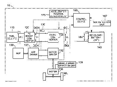
2. Description of Related Art
[0002]
Vehicles that are driven by an electric motor, such as fuel cell vehicles and
electric vehicles, are available in the related art (Japanese Patent
Application Publication
No. 2011-003278 (JP 2011-003278 A)). In these vehicles, a required torque of
the
electric motor is calculated in accordance with an accelerator depression
amount,
whereupon the electric motor is controlled such that an effective torque of
the electric
motor approaches the required torque.
[0003] In a
typical torque characteristic of an electric motor, however, a torque
output response is higher than that of an internal combustion engine, and
therefore a rate at
which the effective torque increases relative to the accelerator depression
amount is high
from a low speed. Hence, when a driver depresses an accelerator pedal at a low
speed, a
sensation of the vehicle shooting forward against the will of the driver may
be generated.
When the rate at which the effective torque increases relative to the
accelerator depression
amount is set to be small at all times, on the other hand, an acceleration
feeling relative to
the accelerator depression amount may deteriorate. As a result, there remains
room for
improvement in a method of determining the rate at which the effective torque
increases
relative to the accelerator depression amount.
CA 02911941 2015-11-13
TSN201505231CA00
TFN150652-CA
2
SUMMARY OF THE INVENTION
[0004] The
invention provides a vehicle in which a rate at which an effective
torque of an electric motor increases relative to an accelerator operation
amount can be set
appropriately, and a method of controlling the vehicle.
[0005] According to a
first aspect of the invention, a vehicle driven by an electric
motor, includes: an accelerator operation amount detection unit that detects
an accelerator
operation amount of the vehicle; a speed detection unit that detects a vehicle
speed of the
vehicle; and a control unit configured to calculate a required torque of the
electric motor on
a basis of the accelerator operation amount and the vehicle speed, calculate a
torque
increase rate, which is a required rate at which an effective torque for
driving the electric
motor is increased, on a basis of the required torque, and control the
electric motor on a
basis of the calculated torque increase rate. The control unit is configured
to control the
electric motor to operate at a predetermined torque increase rate until the
effective torque
reaches a predetermined threshold torque, and to reduce the torque increase
rate below the
predetermined torque increase rate after the effective torque reaches the
predetermined
threshold torque. According to this configuration, a sufficient torque
response is secured
when an accelerator operation is started from a stationary condition, for
example, and
therefore a sensation of sluggishness at the start of the accelerator
operation can be
suppressed. When the effective torque exceeds the threshold torque, on the
other hand,
the torque increase rate is reduced, and therefore a sensation of the vehicle
shooting
forward against the will of a driver can be suppressed.
[0006] In
the aspect described above, the control unit may include a first
map showing a correspondence relationship between the accelerator operation
amount, the
vehicle speed, and an upper limit value of the torque increase rate, and the
control unit may
be configured to control the electric motor such that, when the effective
torque exceeds the
threshold torque and the torque increase rate exceeds the upper limit value,
the torque
increase rate is reduced to the upper limit value. According to this
configuration, the
upper limit value of the torque increase rate can be set easily in accordance
with the
accelerator operation amount and the vehicle speed using the first map. On the
first map,
CA 02911941 2015-11-13
TSN201505231CA00
TFN150652-CA
3
for example, the upper limit value of the torque increase rate may be reduced
when the
vehicle speed is low and the accelerator operation amount is small, and
increased steadily
as the accelerator operation amount increases. In this case, the sensation of
the vehicle
shooting forward against the will of the driver when an accelerator operation
is performed
at a low speed can be suppressed easily. Meanwhile, deterioration of an
acceleration
feeling relative to the accelerator operation amount when a large accelerator
operation is
performed can be suppressed. Furthermore, according to this configuration, the
upper
limit value of the torque increase rate at which the driver feels most
comfortable can be set
easily for each vehicle speed, for example. As a result, an improvement in
drivability can
be achieved.
[0007] In
the configuration described above, the control unit may include a
second map showing a correspondence relationship between the vehicle speed and
the
threshold torque, and the second map may be set such that a value of the
threshold torque
when the vehicle speed is relatively high equals or exceeds a value of the
threshold torque
when the vehicle speed is relatively low. According to this configuration, the
threshold
torque is set to increase as the vehicle speed increases. Hence, the torque
increase rate
can exceed the set upper limit value at each vehicle speed until the effective
torque reaches
the threshold torque, and therefore the acceleration feeling of the vehicle
can be improved.
As a result, a sufficient torque response is secured when an accelerator
operation is started
from a stationary condition, for example, whereby a sensation of sluggishness
at the start
of the accelerator operation can be suppressed. Meanwhile, when the effective
torque
exceeds the threshold torque, the torque increase rate is reduced to the set
upper limit value,
and therefore the sensation of the vehicle shooting forward against the will
of the driver
can be suppressed.
[0008] In the
configuration described above, the first map may be set such that
the upper limit value when the accelerator operation amount is relatively
large equals or
exceeds the upper limit value when the accelerator operation amount is
relatively small.
According to this configuration, deterioration of the acceleration feeling
relative to the
acceleration operation amount when a large accelerator operation is performed
can be
CA 02911941 2015-11-13
TSN201505231CA00
TFN150652-CA
4
suppressed.
[0009] In
the configuration described above, the first map may be set such that
while the accelerator operation amount is equal to or smaller than a threshold
operation
amount, the upper limit value when the vehicle speed is no lower than a first
threshold
vehicle speed and no higher than a second threshold vehicle speed is smaller
than the upper
limit value when the vehicle speed is lower than the first threshold vehicle
speed and
higher than the second threshold vehicle speed. According to this
configuration, the
upper limit value of the torque increase rate is relatively high when an
accelerator
operation is started from a stationary condition, and therefore a sufficient
torque response
can be secured when an accelerator operation is started from a stationary
condition. As a
result, a sensation of sluggishness at the start of the accelerator operation
can be
suppressed. Meanwhile, the upper limit value of the torque increase rate is
relatively low
at a low vehicle speed and a small accelerator depression amount, and
therefore the
sensation of the vehicle shooting forward against the will of the driver can
be suppressed.
Moreover, the upper limit value of the torque increase rate is relatively high
at a high
vehicle speed, and therefore deterioration of the acceleration feeling
relative to the
accelerator operation amount when an accelerator operation is performed can be
suppressed.
[0010]
According to a second aspect of the invention, a control method for a
vehicle that is driven by an electric motor, includes: detecting an
accelerator operation
amount and a vehicle speed of the vehicle; calculating a required torque of
the electric
motor on a basis of the accelerator operation amount and the vehicle speed;
calculating a
torque increase rate, which is a required rate at which an effective torque
for driving the
electric motor is increased, on a basis of the required torque; controlling
the electric motor
on a basis of the calculated torque increase rate. The electric motor is
controlled to
operate at a predetermined torque increase rate until the effective torque
reaches a
predetermined threshold torque, and the electric motor is controlled such that
the torque
increase rate is reduced below the predetermined torque increase rate after
the effective
torque reaches the predetermined threshold torque. According to this
configuration, a
CA 02911941 2015-11-13
TSN201505231CA00
TFN150652-CA
sufficient torque response is secured when an accelerator operation is started
from a
stationary condition, for example, and therefore a sensation of sluggishness
at the start of
the accelerator operation can be suppressed. When the effective torque exceeds
the
threshold torque, on the other hand, the torque increase rate is reduced, and
therefore a
5 sensation of the vehicle shooting forward against the will of a driver
can be suppressed.
BRIEF DESCRIPTION OF THE DRAWINGS
[0011]
Features, advantages, and technical and industrial significance of
exemplary embodiments of the invention will be described below with reference
to the
accompanying drawings, in which like numerals denote like elements, and
wherein:
FIG. 1 is a schematic view showing a configuration of a fuel cell vehicle
according to
a first embodiment;
FIG. 2 is a flowchart illustrating acceleration management control;
FIGS. 3A to 3C are timing charts showing example conditions of the fuel cell
vehicle;
and
FIG. 4 is a view illustrating an acceleration management Tp rate map.
DETAILED DESCRIPTION OF EMBODIMENTS
[0012] FIG.
1 is a schematic view showing a configuration of a fuel cell vehicle
10 according to a first embodiment. The fuel cell vehicle 10 includes a fuel
cell 110, a
fuel cell (FC) boost converter 120, a power control unit (PCU) 130, a traction
motor 136,
an air compressor (ACP) 138, a vehicle speed detection unit 139, a secondary
battery 140,
a state of charge (SOC) detection unit 142, an accelerator position detection
unit 175, a
control device 180, and a vehicle wheel WL. The fuel cell vehicle 10 travels
when the
traction motor 136 is driven by power supplied from the fuel cell 110 and the
secondary
battery 140.
[0013] The
fuel cell 110 is a polymer electrolyte fuel cell that generates power
CA 02911941 2015-11-13
TSN201505231CA00
TFN150652-CA
6
upon reception of supplies of hydrogen and oxygen as reaction gases. Note that
the fuel
cell 110 is not limited to a polymer electrolyte fuel cell, and another type
of fuel cell may
be used. The fuel cell 110 is connected to high pressure direct current wiring
DCH via
the FC boost converter 120, and connected to a motor driver 132 and an ACP
driver 137
included in the PCU 130 via the high pressure direct current wiring DCH. The
FC boost
converter 120 boosts an output voltage VFC of the fuel cell 110 to a high-
pressure voltage
VH that can be used by the motor driver 132 and the ACP driver 137.
[0014] The
motor driver 132 is constituted by a three-phase inverter circuit, and
connected to the traction motor 136. The motor driver 132 converts output
power from
the fuel cell 110, supplied via the FC boost converter 120, and output power
from the
secondary battery 140, supplied via a DC/DC converter 134, into three-phase
alternating
current power, and supplies the three-phase alternating current power to the
traction motor
136. The traction motor 136 is constituted by a synchronous motor including a
three-phase coil, and drives the vehicle wheel WL via a gear and so on.
Further, during a
braking operation in the fuel cell vehicle 10, the traction motor 136
functions as a power
generator that generates regenerative power by regenerating kinetic energy
produced by the
fuel cell vehicle 10. The vehicle speed detection unit 139 detects a vehicle
speed SVHCL
(km/h) of the fuel cell vehicle 10 and transmits the detected vehicle speed
SVHCL to the
control device 180.
[0015] The DC/DC
converter 134 switches the secondary battery 140 between a
charging condition and a discharging condition by adjusting a voltage level of
the high
pressure direct current wiring DCH in response to a drive signal from the
control device
180. Note that when regenerative power is generated by the traction motor 136,
the
regenerative power is converted into direct current power by the motor driver
132 and
charged to the secondary battery 140 via the DC/DC converter 134.
[0016] The
ACP driver 137 is constituted by a three-phase inverter circuit, and
connected to an ACP 138. The ACP driver 137 converts the output power from the
fuel
cell 110, supplied via the FC boost converter 120, and the output power from
the secondary
battery 140, supplied via the DC/DC converter 134, into three-phase
alternating current
CA 02911941 2015-11-13
TSN201505231CA00
TFN150652-CA
7
power, and supplies the three-phase alternating current power to the ACP 138.
The ACP
138 is constituted by a synchronous motor including a three-phase coil, and
supplies the
fuel cell 110 with oxygen (air) used during power generation by driving a
motor in
accordance with the supplied power.
[0017] The secondary
battery 140 is a electricity storage device that stores
electric energy and can be charged and discharged repeatedly. The secondary
battery 140
may be constituted by a lithium ion battery, for example. Note that another
type of
battery, such as a lead storage battery, a nickel cadmium battery, or a nickel
hydrogen
battery, may be used as the secondary battery 140 instead. The secondary
battery 140 is
connected to the DC/DC converter 134 included in the PCU 130 via a low
pressure direct
current wiring DCL, and connected to the high pressure direct current wiring
DCH via the
DC/DC converter 134.
[0018] The
SOC detection unit 142 detects the SOC of the secondary battery 140,
and transmits the detected SOC to the control device 180. The SOC detection
unit 142
detects a temperature T, an output voltage V, and an output current I of the
secondary
battery 140, and detects the SOC on a basis of these detection values. The
accelerator
position detection unit 175 serves as an accelerator operation amount
detection unit so as to
detect, as an accelerator operation amount, an amount by which a driver
depresses an
accelerator pedal (an accelerator depression amount DAM (%), and transmits the
detected
accelerator depression amount DACC to the control device 180. Note that the
fuel cell
vehicle 10 may also include auxiliary devices used during power generation by
the fuel cell
110, such as a fuel pump and a coolant pump, and an air-conditioning device
such as an
air-conditioner.
[0019] The
control device 180 is constituted by a microcomputer having a central
processing unit and a main storage device. The control device 180 may be an
electronic
control unit (ECU). When an operation performed by the driver such as an
accelerator
operation is detected, the control device 180 controls power generation by the
fuel cell 110
and charging/discharging of the secondary battery 140 in accordance with the
content of
the operation. The control device 180 generates a drive signal corresponding
to the
CA 02911941 2015-11-13
TSN201505231CA00
TFN150652-CA
8
accelerator depression amount DACC, and transmits the generated drive signal
to each of the
motor driver 132 and the DC/DC converter 134. In response to the drive signal
from the
control device 180, the motor driver 132 drives the traction motor 136 to
rotate in
accordance with the accelerator depression amount DAcc by adjusting a pulse
width of an
.. alternating current voltage and so on.
[0020] The
control device 180 calculates a required torque TRQ (N x m) from the
accelerator depression amount DAcc detected by the accelerator position
detection unit 175
and the vehicle speed SVFICL detected by the vehicle speed detection unit 139.
The
required torque TRQ is an amount of torque (a target torque) required by the
traction motor
136, and can be calculated using a map that shows relationships between the
accelerator
depression amount DAcc, the vehicle speed SvitcL, and the required torque TRQ.
Further,
the control device 180 controls the traction motor 136 such that a torque (an
effective
torque) TAC x m)
actually generated by the traction motor 136 approaches the calculated
required torque TRQ. Here, the effective torque TAC is a torque (Tp) of a
propeller shaft.
At this time, the control device 180 executes acceleration management control
to control
an increase rate of the effective torque TAC. The increase rate of the
effective torque TAC
will be referred to here as a Tp rate RAT. The Tp rate RATp is an amount by
which the
effective torque TAC increases per calculation period of the control device
180. During
the acceleration management control, the control device 180 calculates the Tp
rate RArp
from the accelerator depression amount DAcc and the vehicle speed SvHcL, and
controls the
effective torque I'm of the traction motor 136 to the calculated Tp rate RAT.
The Tp rate
RAfp according to this embodiment functions as a torque increase rate.
[0021] FIG 2
is a flowchart illustrating the acceleration management control.
The control device 180 executes the acceleration management control described
below
repeatedly at predetermined period intervals when the driver switches an
ignition ON.
First, the control device 180 calculates a Tp rate base value BRAT that serves
as a base
value when calculating the Tp rate RATp (step S110). The Tp rate base value
BRATp can
be calculated from Equation (1), shown below.
BRATp = TDIF + TOFST + TRTH (1)
CA 02911941 2015-11-13
TSN201505231CA00
TFN150652-CA
9
Here, TDIF is a difference (TRQ ¨ TAc) between the required torque TRQ and the
effective torque TAC = TQFST is a value (> 0) set in advance as an offset
value of RAT!).
TRTH is a value 0) set in advance in accordance with the value of the
effective torque TAC
in order to suppress gear rattle occurring when the effective torque TAQ
shifts from a
negative value to a positive value. Here, TRTH takes a negative value when the
effective
torque TAc is within a predetermined range close to zero, and takes a value of
zero when
the value of the effective torque TAc is not within the predetermined range.
100221 Next,
the control device 180 calculates a Tp rate changeover torque TCHG,
which is a threshold of the effective torque TAc used to calculate the Tp rate
RATp (step
S120). The control device 180 includes a map (an SVHCL TCHG map) showing a
correspondence relationship between the vehicle speed SVHCL and the Tp rate
changeover
torque TCHG, and calculates the Tp rate changeover torque TCHG from the
vehicle speed
SVHCL and the SVHCL ¨ TCHG map. The SVHCL TCHG map is set such that the Tp
rate
changeover torque TCHG increases steadily as the vehicle speed SVHCL
increases. In other
words, the control device 180 switches the Tp rate changeover torque TCHG as
the vehicle
speed SVHCL increases. Note that the SVHCL TcHQ map may be set such that a
value of
the Tp rate changeover torque TCHG when the vehicle speed SVHCL is relatively
high equals
or exceeds the value of the Tp rate changeover torque TCHG when the vehicle
speed SVHCL
is relatively low. In other words, a region in which the Tp rate changeover
torque TCHG
does not vary even when the vehicle speed SVHCL increases may exist on the
SVHCL ¨ TCHG
map. For example, the value of the Tp rate changeover torque Tom may be set on
the
SVHCL TCHG map in respective speed ranges (0 to 10, 10 to 20, ... (km/h), for
example)
corresponding to the vehicle speed SVHCL. The Tp rate changeover torque TCHG
according
to this embodiment functions as a threshold torque. The SVHCL TCHG map
functions as a
second map.
100231 Next,
the control device 180 calculates an acceleration management Tp
rate MRATp that is used as an upper limit value of the Tp rate RATp (step
S130). The
control device 180 includes a map (an acceleration management Tp rate map)
that shows
correspondence relationships between the accelerator depression amount DAQQ,
the vehicle
CA 02911941 2015-11-13
TSN201505231CA00
TFN150652-CA
speed SvHcL, and the acceleration management Tp rate MRATp, and calculates the
acceleration management Tp rate MRATp from the accelerator depression amount
DACC,
the vehicle speed SVHCL, and the acceleration management Tp rate map. A
specific
configuration of the acceleration management Tp rate map will be described
below. The
5 acceleration management Tp rate MRATp according to this embodiment functions
as an
upper limit value of the torque increase rate. The acceleration management Tp
rate map
functions as a first map.
[0024] The
control device 180 determines whether or not the effective torque TAC
exceeds the Tp rate changeover torque TCHG (step S140). When the effective
torque TAC
10 does not exceed the Tp rate changeover torque TCHG (TAC TCHG), the
control device 180
calculates the value of the Tp rate base value BRATp as the Tp rate RATp (step
S145).
The control device 180 then controls the effective torque I'm of the traction
motor 136 to
the calculated Tp rate RATp.
[0025] When
the effective torque 'I'm exceeds the Tp rate changeover torque
To (TAC > TCHG), on the other hand, the control device 180 determines whether
or not the
Tp rate base value BRATp exceeds the acceleration management Tp rate MRA-rp
(step
S150). When the Tp rate base value BRATp does not exceed the acceleration
management Tp rate MRA-rp (BRATp MRATp), the control device 180 calculates the
value of the Tp rate base value BRATp as the Tp rate RATp (step S145). The
control
device 180 then controls the effective torque TAC of the traction motor 136 to
the
calculated Tp rate RATp.
[0026] When
the Tp rate base value BRATp exceeds the acceleration management
Tp rate MRArp (BRATp > MRA-rp), on the other hand, the control device 180
calculates the
value of the acceleration management Tp rate MRATp as the Tp rate RATp (step
S160).
Here, the acceleration management Tp rate MRATp functions as an upper limit
value (a
guard value) of the Tp rate base value BRAT. Note that in order to suppress
rapid
reduction in the calculated Tp rate RATp, the control device 180 may calculate
the Tp rate
RATp in step S160 by performing rate processing (smoothing processing) on a
decrease
rate of the Tp rate RATp so that the decrease rate of the Tp rate RATp does
not equal or
CA 02911941 2015-11-13
TSN201505231CA00
TFN150652-CA
11
exceed a predetermined rate. In other words, the Tp rate RATp may be
calculated so that a
difference between the Tp rate base value BRATp and the acceleration
management Tp rate
MRATp decreases gradually. In so doing, torque shock can be suppressed.
[0027]
Hence, when the effective torque TAc does not exceed the Tp rate
changeover torque TcHG during the acceleration management control, the control
device
180 calculates the value of the Tp rate base value BRA-rp as the Tp rate RATp
regardless of
whether or not the value of the Tp rate base value BRATp exceeds the
acceleration
management Tp rate MRATp. As a result, the effective torque TAc can be brought
close to
the required torque TRQ quickly, thereby suppressing a sensation of
sluggishness in the
vehicle when the accelerator pedal is depressed. When the effective torque TAc
exceeds
the Tp rate changeover torque TcHG, on the other hand, the control device 180
reduces the
Tp rate RA-rp to the acceleration management Tp rate MRATp. As a result, a
sensation of
the vehicle shooting forward against the will of the driver when the
accelerator pedal is
depressed can be suppressed.
[0028] FIGS. 3A to 3C
are timing charts showing example conditions of the fuel
cell vehicle 10 according to this embodiment. FIG 3A shows time series
variation in the
accelerator depression amount DAcc and the vehicle speed SvHcL. FIG. 3B shows
time
series variation in the required torque TRQ, the effective torque TAc, and the
Tp rate
changeover torque TcHG. FIG. 3C shows time series variation in the Tp rate
RATp and the
acceleration management Tp rate MRATp. In the case described below, the driver
does
not depress the accelerator during a period from TO to T1, depression of the
accelerator
starts at the time Ti, and from a time T3 onward, the accelerator depression
amount
remains constant. Further, in the case described below, variation in the
vehicle speed
SvHCL is small, and therefore the value of the Tp rate changeover torque TcHG
is not
switched. Furthermore, in the case described below, TRTH of Equation (1) takes
a
negative value when the Tp rate RATp is calculated during a period from T2 to
T4.
[0029]
During the period from TO to TI, the accelerator depression amount DACC
is zero, and therefore the control device 180 calculates the required torque
TRQ as a
negative value. Accordingly, negative acceleration is generated in the fuel
cell vehicle 10.
CA 02911941 2015-11-13
TSN201505231CA00
TFN150652-CA
12
Further, since substantially no variation occurs in either the accelerator
depression amount
DACC or the vehicle speed SVHCL, the control device 180 calculates the
acceleration
management Tp rate MRATp as a substantially constant value. Since TDIF and
TRTH of
Equation (1) are both zero, the control device 180 calculates the value of
T0FsT as the Tp
rate RATp, but since the effective torque TAc is already equal to the required
torque TRQ
serving as the upper limit value, the control device 180 does not increase the
effective
torque TAc on a basis of the Tp rate RATp.
[0030]
During a period from T1 to T3, the accelerator depression amount DACC
increases rapidly, and therefore the control device 180 rapidly increases the
calculated
required torque TRQ and acceleration management Tp rate MRATp. The effective
torque
TAc increases at a delay relative to the required torque TRQ, and therefore
the difference
(TRQ ¨ TAc) between the required torque TRQ and the effective torque TAc
increases.
From the time T3 onward, substantially no variation occurs in either the
accelerator
depression amount DACC or the vehicle speed SvHcT, and therefore the control
device 180
calculates the respective values of the required torque TRQ and the
acceleration
management Tp rate MRATp to be constant. During a period from T3 to T7, the
effective
torque TAc gradually approaches the required torque TRQ, and at the time T7,
the effective
torque TAc becomes equal to the required torque TRQ.
[0031]
During the period from Ti to T2, TDIF of Equation (1) increases while
TRTH remains at zero, and therefore the control device 180 increases the
calculated Tp rate
RATp and increases the effective torque TAc to correspond to the Tp rate RATp.
During a
period from T2 to T4, TDIF of Equation (1) increases while TRTH falls greatly
below zero,
and therefore the control device 180 reduces the calculated Tp rate RATp and
causes the
effective torque Tqc to rise less sharply. At the time T4, TRTH of Equation
(1) returns to
zero, and therefore the control device 180 increases the calculated Tp rate
RATp and
increases the effective torque TAc to correspond to the Tp rate RATp. Note
that at the time
T4, the effective torque TAc does not yet exceed the Tp rate changeover torque
TcHG (step
S140 in FIG 2: No), and therefore the value of the Tp rate RATp may exceed the
acceleration management Tp rate MRATp. Hence, the increase rate of the
effective torque
CA 02911941 2015-11-13
TSN201505231CA00
TFN150652-CA
13
TAc can be kept high, enabling an improvement in an acceleration feeling of
the vehicle.
[0032] When
the effective torque TAc exceeds the Tp rate changeover torque
TcHG (step S140 in FIG. 2: Yes) and the Tp rate RATp exceeds the acceleration
management
Tp rate MRATp (step S150 in FIG. 2: Yes), as occurs at a time T5, the control
device 180
reduces the value of the Tp rate MRATp to the acceleration management Tp rate
MRATp
serving as the upper limit value (step S160 in FIG. 2). Here, the control
device 180
calculates the Tp rate RATp by performing rate processing (smoothing
processing) on the
decrease rate of the Tp rate RATp, and therefore the calculated Tp rate RATp
takes a larger
value than the acceleration management Tp rate MRATp. In a period from T5 to
T6, the
control device 180 reduces the value of the calculated Tp rate RATp such that
at the time T6,
the value of the Tp rate RArp becomes equal to the acceleration management Tp
rate
MRATp. Hence, when the effective torque TAc exceeds the Tp rate changeover
torque
TcHG, the control device 180 reduces the increase rate of the effective torque
TAc (the Tp
rate RAT) to the set upper limit value (the acceleration management Tp rate
MRATp). As
a result, the sensation of the vehicle shooting forward against the will of
the driver when
the accelerator pedal is depressed can be suppressed. Note that at the time
T7, THw of
Equation (1) reaches zero, and therefore the control device 180 reduces the
calculated Tp
rate RATp.
[0033] FIG.
4 is a view illustrating the acceleration management Tp rate map.
FIG. 4 shows a relationship between the vehicle speed SVFICL and the
acceleration
management Tp rate MRATp at each accelerator depression amount DACC. The
control
device 180 includes the acceleration management Tp rate map shown in FIG 4,
and
calculates the acceleration management Tp rate MRATp from the accelerator
depression
amount DACC, the vehicle speed SvHcL, and the acceleration management Tp rate
map. In
the fuel cell vehicle 10 according to this embodiment, the acceleration
management Tp rate
MRATp corresponding to the accelerator depression amount DACC and the vehicle
speed
SvHCL can be set easily using the acceleration management Tp rate map.
Accordingly, the
acceleration management Tp rate MRATp at which the driver feels most
comfortable can be
set easily for each vehicle speed SvHcL and each accelerator depression amount
DACC, and
CA 02911941 2015-11-13
TSN201505231CA00
TFN150652-CA
14
as a result, an improvement in drivability can be achieved.
[0034] On
the acceleration management Tp rate map, the acceleration
management Tp rate MRATp is set to increase in value steadily as the
accelerator
depression amount DAcc increases. Accordingly, deterioration of the
acceleration feeling
relative to the accelerator depression amount DAcc when the accelerator pedal
is depressed
by a large amount can be suppressed. Note that the acceleration management Tp
rate map
may be set such that the acceleration management Tp rate MRATp when the
accelerator
depression amount DAcc is relatively large equals or exceeds the acceleration
management
Tp rate MRA-rp when the accelerator depression amount DAcc is relatively
small. In other
words, a region in which the acceleration management Tp rate MRArp does not
vary even
when the vehicle speed Sviin increases may exist on the acceleration
management Tp rate
map.
[0035]
Further, on the acceleration management Tp rate map, while the
accelerator depression amount DAcc is at or below a threshold depression
amount THD
serving as a threshold operation amount, the acceleration management Tp rate
MRATp
when the vehicle speed SvHa is no lower than a first threshold vehicle speed
THS1 and no
higher than a second threshold vehicle speed THS2 is set to be relatively
smaller than the
acceleration management Tp rate MRATp when the vehicle speed SvHCL is lower
than the
first threshold vehicle speed THS1 and higher than the second threshold
vehicle speed
THS2. The threshold depression amount THD, the first threshold vehicle speed
THS1,
and the second threshold vehicle speed THS2 are set at appropriate values at
which the
driver is most comfortable. For example, the threshold depression amount THD
may be
approximately 60 to 80%, the first threshold vehicle speed THS1 may be
approximately 20
to 40 km/h, and the second threshold vehicle speed THS2 may be approximately
60 to 80
km/h. Hence, the acceleration management Tp rate MRATp when the accelerator
pedal is
initially depressed from a stationary condition is relatively high, and
therefore a sufficient
torque response can be secured when the accelerator pedal is initially
depressed from a
stationary condition, whereby a sensation of sluggishness upon initial
depression of the
accelerator pedal can be suppressed. On the other hand, the acceleration
management Tp
CA 02911941 2015-11-13
TSN201505231CA00
TFN150652-CA
rate MRATp at a low vehicle speed and a small accelerator depression amount is
relatively
low, and therefore the sensation of the vehicle shooting forward against the
will of the
driver can be suppressed. Moreover, the acceleration management Tp rate MRATp
at a
high vehicle speed is relatively high, and therefore deterioration of the
acceleration feeling
5 relative
to the accelerator depression amount DAcc upon depression of the accelerator
pedal can be suppressed.
[0036] The
fuel cell vehicle 10 according to this embodiment, described above, is
configured to operate at a predetermined Tp rate RATp until the effective
torque TAc
reaches the Tp rate changeover torque TcHG, and such that the Tp rate RATp is
reduced after
10 the
effective torque TAc reaches the Tp rate changeover torque TcHG. According to
this
configuration, a sufficient torque response can be secured when the
accelerator pedal is
initially depressed from a stationary condition, for example, whereby the
sensation of
sluggishness upon initial depression of the accelerator pedal can be
suppressed. When the
effective torque exceeds the threshold torque, on the other hand, the torque
increase rate is
15 reduced,
and therefore the sensation of the vehicle shooting forward against the will
of the
driver can be suppressed.
100371
Further, the fuel cell vehicle 10 according to this embodiment includes the
acceleration management Tp rate map, and therefore the acceleration management
Tp rate
MRATp corresponding to the accelerator depression amount DAcc and the vehicle
speed
SVHCL can be set easily. Hence, the acceleration management Tp rate MRATp at
which the
driver feels most comfortable can be set easily for each vehicle speed SVHCL
and each
accelerator depression amount DAcc. For
example, by making the acceleration
management Tp rate MRATp at a low vehicle speed and a small accelerator
depression
amount relatively low, the sensation of the vehicle shooting forward against
the will of the
driver when the accelerator pedal is depressed at a low speed can be
suppressed.
Furthermore, for example, by increasing the acceleration management Tp rate
MRATp
steadily as the accelerator depression amount DAcc increases, deterioration of
the
acceleration feeling relative to the accelerator depression amount DACC when
the
accelerator pedal is depressed by a large amount can be suppressed.
CA 02911941 2015-11-13
TSN201505231CA00
TFN150652-CA
16
[0038]
Moreover, the fuel cell vehicle 10 according to this embodiment includes
the SVHCL TCHG map, and therefore the Tp rate RATp can exceed the acceleration
management Tp rate MRATp at each vehicle speed until the effective torque TAc
reaches
the Tp rate changeover torque TcHG, enabling an improvement in the
acceleration feeling
of the vehicle. As a result, a sufficient torque response is secured when the
accelerator is
initially depressed from a stationary condition, for example, whereby the
sensation of
sluggishness upon initial depression of the accelerator pedal can be
suppressed. When the
effective torque TAc exceeds the Tp rate changeover torque TcHG, on the other
hand, the Tp
rate RATp is reduced to the Tp rate changeover torque TcHG, and therefore the
sensation of
the vehicle shooting forward against the will of the driver can be suppressed.
[0039] Note
that the invention is not limited to the embodiment described above,
and may be implemented in various other embodiments within a scope that does
not depart
from the spirit thereof. For example, following amendments may be implemented.
[0040] In
this embodiment, the invention is realized as the fuel cell vehicle 10,
but the invention may be applied to a vehicle not having a fuel cell. For
example, the
invention may be applied to an electric vehicle or a hybrid vehicle.
[0041] In
this embodiment, the Tp rate changeover torque TcHG is described as
being calculated from the vehicle speed SVHCL and the SvHci, ¨ TcHG map, but
the Tp rate
changeover torque TcHG may take a single fixed value. In this case, the fuel
cell vehicle
10 need not include the SVHCL TCHG map.
[0042] The
acceleration management Tp rate map is not limited to the content
described above. For example, the acceleration management Tp rate map need not
be set
such that while the accelerator depression amount DACC is at or below the
threshold
depression amount THD, the acceleration management Tp rate MRATp when the
vehicle
speed SVHCL is no lower than the first threshold vehicle speed THS1 and no
higher than the
second threshold vehicle speed THS2 decreases relative to the acceleration
management Tp
rate MRATp when the vehicle speed SVHCL is lower than the first threshold
vehicle speed
THS1 and higher than the second threshold vehicle speed THS2 as the
accelerator
depression amount DAcc increases. Likewise in this case, other acceleration
management
CA 02911941 2015-11-13
TSN201505231CA00
T150652-CA
17
Tp rates MRATp at which the driver feels most comfortable can be set easily in
accordance
with the vehicle speed SvHcL and the accelerator depression amount DACC.
100431 Note
that the invention may be realized in various forms, for example as a
fuel cell vehicle, a hybrid vehicle, an electric vehicle, a control method for
a vehicle driven
by an electric motor, a control apparatus for executing the control method, a
computer
program for realizing the control method, a recording medium on which the
computer
program is recorded, and so on.