Note: Descriptions are shown in the official language in which they were submitted.
CA 02912558 2015-11-19
,
WaveLight GmbH - 1 -
1A-125 751
System and controlling method thereof
for performing measurements of an eye
Technical Field
The present disclosure generally relates to a controlling method of a system
for per-
forming measurements of an eye and said system using the method.
Background
For eye surgery (e.g., LASIK surgery), measurement information such as corneal
tissue shape and thickness and eye position may be obtained by a measurement
tool
such as a diagnostic device (e.g., an aberrometer, autorefractor, a
keratometer, a
corneal topographer, or an Optical Coherence Tomographer) or therapeutic
device
performing the eye surgery.
Typically, said devices must be adjusted to the specific dimensions of the
patient. For
zo example, when performing diagnostic measurements on a patient for
refractive sur-
gery, a user may operate a joystick of a diagnostic device to find a patient's
eye. Said
joystick may control a stage or other means that positions the diagnostic
device,
relative to the patient, for obtaining diagnostic measurements.
To explain further, a camera may be used to find a patient's eye, an image of
which
is displayed to the diagnostic device user. The diagnostic device may further
display
symbols to provide assistance regarding the direction that the system needs to
be
moved, via the joystick, for obtaining optimum positioning for measurement.
Once
the position is obtain, measurement processes are triggered for obtaining
various
optical properties of the patient's eye.
It may be necessary to adjust the stage when patients slightly move before,
during,
and/or after the measurement process or even leave from and return to the meas-
urement position. In such cases, the stage needs to be reconfigured for
subsequent
measurements.
CA 02912558 2015-11-19
=
WaveLight GmbH - 2 - 1A-
125 751
Summary
Accordingly, there is a need for systems and methods that can quickly and
consis-
tently place measurement tools in appropriate measurement positions.
According to one aspect, a system for performing measurements of an eye
compris-
es: a measurement tool for performing measurements of the eye, the measurement
tool including an objective and implementing an image capturing function using
the
objective; at least one rest designed to maintain a facial measurement
position, the
at least one rest defining a centering rest portion designed to maintain a
lateral facial
measurement position; an adjuster mechanism adapted to move the objective rela-
tive to the eye; and a processing unit configured to control the system to:
position,
via the adjuster mechanism and for a first eye, the objective at a predefined
first pre-
scan position; scan, via the adjuster mechanism, the objective away from the
first
pre-scan position until the system detects a pupil of the first eye; and
trigger one or
more measurements of the first eye via the measurement tool dependent on the
system detecting the pupil of the first eye.
In certain embodiments, the processing unit is further configured to control
the sys-
tern to: position, via the adjuster system and for a second eye, the objective
at a
predefined second pre-scan position that is different from the first pre-scan
position;
scan, via the adjuster system, the objective away from the second pre-scan
position
until the system detects a pupil of the second eye; trigger one or more
measure-
ments of the second eye via the measurement tool dependent on the system
detect-
ing the pupil of the second eye.
In certain embodiments, the second pre-scan position mirrors the first scan
position
with respect to a vertical axis passing through the centering rest portion.
In certain embodiments, the processing unit is configured to control the
system to
scan, via the adjuster mechanism, the objective away from the first pre-scan
position
along a vertical direction.
In certain embodiments, the processing unit is configured to control the
system to
scan, via the adjuster mechanism, the objective away from the second pre-scan
position along a vertical direction.
CA 02912558 2015-11-19
WaveLight GmbH - 3 - 1A-
125 751
In certain embodiments, the measurement tool includes an image sensor for
captur-
ing images.
In certain embodiments, the at least one rest comprises a chin rest, wherein
an im-
age captured by the measurement tool in the first pre-scan position of the
objective
covers a facial area higher than a statistical maximum pupil height or lower
than a
statistical minimum pupil height relative to the chin rest.
In certain embodiments, an image captured by the measurement tool in the
second
pre-scan position of the objective covers a facial area higher than a
statistical maxi-
mum pupil height or lower than a statistical minimum pupil height relative to
the chin
rest.
In certain embodiments, an image captured by the measurement tool in the first
pre-
scan position of the objective covers a facial area having a lateral position
and lateral
width appropriate to accommodate statistical variations of a pupillary
distance from a
vertical center axis passing through the centering rest portion.
In certain embodiments, the processing unit is configured to control the
system to
zo record coordinate information of at least one of: a scan position
related to the system
detecting the pupil of the first eye, and a scan position related to the
system trigger-
ing the one or more measurements of the first eye.
In certain embodiments, the processing unit is configured to control the
system to
record coordinate information of at least one of: a scan position related to
the system
detecting the pupil of the second eye, and a scan position related to the
system
triggering the one or more measurements of the second eye.
In certain embodiments, the processing unit is configured to control the
system to
retrieve the recorded coordinate information and re-adjust the objective based
on the
retrieved coordinate information.
In certain embodiments, the at least one rest comprises a chin rest adapted to
be
positionally adjustable via the adjuster mechanism, wherein the processing
unit is
configured to control the system to record position information of the chin
rest in
association with the coordinate information, retrieve the recorded position
infor-
mation and re-adjust, via the adjuster mechanism, the chin rest in accordance
with
the retrieved position information.
CA 02912558 2015-11-19
WaveLight GmbH - 4 - 1A-
125 751
In certain embodiments, the processing unit is configured to control the
system to
finely adjust the objective in at least the Z direction for focusing on a
detected pupil
of an eye.
In certain embodiments, the processing unit is configured to control the
system to
retract the objective away from the first eye after completion of the
triggered one or
more measurements of the first eye.
In certain embodiments, the measurement tool comprises an optical coherence to-
mography device configured to emit a beam of measurement radiation through the
objective.
According to another aspect, a non-transitory computer-readable memory
contains a
program which, when loaded in a computer or processor or running on a computer
or processor, causes the computer processor to control the above system, said
con-
trol comprising: positioning, via the adjuster mechanism and for a first eye,
the ob-
jective at a predefined first pre-scan position; scanning, via the adjuster
mechanism,
the objective away from the first pre-scan position until the system detects a
pupil of
the first eye; and triggering one or more measurements of the first eye via
the
measurement tool dependent on the system detecting the pupil of the first eye.
According to yet another aspect, a controlling method of a system for
performing
measurements of an eye is provided, wherein the system includes a measurement
tool for performing measurements of the eye, the measurement tool including an
objective and implementing an image capturing function using the objective, at
least
one rest designed to maintain a facial measurement position, the at least one
rest
defining a centering rest portion designed to maintain a lateral facial
measurement
position, and an adjuster mechanism adapted to move the objective relative to
the
eye, the method comprising: positioning, via the adjuster mechanism and for a
first
eye, the objective at a predefined first pre-scan position; scanning, via the
adjuster
mechanism, the objective away from the first pre-scan position until the
system
detects a pupil of the first eye; and triggering one or more measurements of
the first
eye via the measurement tool dependent on the system detecting the pupil of
the
first eye.
Brief Description of the Drawings
CA 02912558 2015-11-19
WaveLight GmbH - 5 - 1A-
125 751
Embodiments of the present disclosure will be further detailed based on the
following
figures, of which:
Fig. 1 schematically illustrates an example diagnostic system;
Fig. 2 schematically illustrates an example computer system;
Figs. 3A schematically illustrate an example diagnostic system and a
patient;
and 3B and
Figs. 4A are flow charts illustrating method embodiments for controlling
a
to 4C system for performing measurements of an eye by a measurement
tool.
Detailed Description
In the following, for purposes of explanation and not limitation, specific
details are
set forth, such as particular sequences of steps, components and
configurations, in
order to provide a thorough understanding of the present invention. It will be
appar-
ent to one skilled in the art that the' present invention may be practiced in
other
embodiments that depart from these specific details.
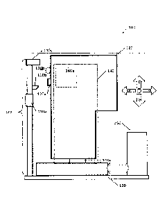
In Fig. 1, system 100 is schematically shown. System 100 includes patient
interface
110. Patient interface 110 includes height adjuster 110a, chin rest 110b, and
fore-
head rest 110c. Adjuster 110a adjusts the height of at least chin rest 110b
via, for
example, mechanical or electromechanical means. For example, adjuster 110a may
be mechanical fastener that is locked and unlocked by a patient or user
turning ad-
juster 110a so to adjust and fix the height of chin rest 110b.
Although two rests are shown, some embodiments may include a single rest that
maintains a measurement position of the patient. For example, chin rest 110b
may
be enlarged to engage a larger portion of a patient's face so to prevent
facial pitch
movement, e.g., head nodding.
Chin rest 110b and forehead rest 110c are arranged and structured for coupling
with
a patient's face such that the patient faces towards optics 120a of
measurement tool
120 for measuring an eye. Measurement tool 120 may be an Optical Coherence To-
mographer. Chin rest 110b and forehead rest 110c may be further arranged and
CA 02912558 2015-11-19
WaveLight GmbH - 6 - 1A-
125 751
structured for defining and maintaining a lateral facial measurement position
with
respect to the measurement tool 120, as explained in more detail below.
Table 130 supports both patient interface 110 and measurement tool 120.
Adjuster
__ mechanism 140 may include adjusters 140a and 140b operable to move measure-
ment tool 120 and/or optics 120a (e.g., a scanning camera objective) and 120b,
in
the X, Y, and Z directions relative to patient interface 110. For example,
optics 120a
may be operable to move in the X, Y, and Z directions relative to patient
interface
110 independently of adjuster 140a via adjuster 140b. More particularly,
optics 120a
lo __ may be coupled to electromechanical means of adjuster 140b operable for
making
said adjustments.
In another example embodiment, adjuster 140b may be operable to move optics
120a in the Z directions independently of adjuster 140a, whereas adjuster 140a
may
__ be operable in at least the X and Y directions, thereby providing X, Y, and
Z direc-
tional movement capabilities for optics 120a. Example adjusters include, but
are not
limited to, translation stages, translation slides, actuators, and optical
focus units for
focusing an optical component.
__ Optics 120a may include an objective that is both a scanning camera
objective used
for pupil detection (described in more detail below) and a focusing objective
for per-
forming measurements an eye. The focusing objective may direct a measurement
beam, such as a laser beam for OCT imaging, onto the eye and receive reflected
radiation or be used in other diagnostic procedures. Examples of a scanning
camera
__ objective include an infrared camera for detecting Purkinje reflexes and a
camera for
taking images in the visible wavelength range.
In alternative embodiments, optics 120a may include the scanning camera
objective
and optics 120b may include the focusing objective. In this case, optics 120a
and
__ 120b may move in unison in the X, Y, and Z directions relative to patient
interface
110 via adjuster 140a and/or adjuster 140b, as described above.
System 100 may further includes computer system 150 that is communicatively
cou-
pled with adjuster mechanism 140 via wired and/or wireless means. Computer sys-
__ tern 150 may include non-transitory computer readable memory for storing
instructions for controlling, via a processor, other components of the
diagnostic sys-
tem (e.g., adjuster mechanism 140) according to present embodiments.
CA 02912558 2015-11-19
WaveLight GmbH - 7 - 1A-
125 751
As shown in Fig. 2, computer system 150 may include memory modules such as ROM
and RAM, one or more processors, I/O modules for communicating within and out-
side computer system 150, and user interface modules, such as a joystick,
display,
and keyboard. Embodiments include housing computer system 150 within measure-
s nnent tool 120.
Figs. 3A and 38 show patient 301 engaged with rests 110b and 110c. Rest 110b
includes a centering rest portion indicating a facial centered measurement
position,
wherein a portion of the centering rest portion includes a depression
coinciding with
notational axis 330 showing the presumed axis about which a patient's face is
sub-
stantially symmetrical (e.g., facial features symmetric with respect to the
presumed
axis). Although not explicitly shown, rest 110c may include a similar
depression.
Maximum and minimum scan positions 300a and 300b define a vertical scan range
for optics 120a to scan. Scan positions 300a and 300b may define the lower and
upper limits of the scan range in the Y direction. The chosen limits allow
system 100
to accommodate for variations of pupillary height within the human population
with
respect to, for example, rest 110b (i.e., the distance between rest 110b and a
pa-
tient's pupil with the patient is engaged with rests 110b and 110c). For
example,
scan position 300b may be higher than the maximum height of a pupil, as
measured
from rest 110b. As shown in Fig. 3A, scan positions 300a and 300b are relative
to
rest 110b, but embodiments also include defining search ranges relative to
rest 110c.
Scan positions 300b and 300a may be a pre-scan position of optics 120a that
cap-
tures an image that covers a facial area higher than a statistical maximum
pupil
height, as shown by field of view (FOV) 220a, or lower than a statistical
minimum
pupil height relative to the chin rest. Maximum and minimum pupil heights may
be
derived from a number of sources. Example sources include DIN 33402
("Ergonomics
- human body dimensions - Section 2: values for geometrical tolerances for
head and
eye position"), which provides values applicable to patients between the age
of 18 to
65. Similar data can be found in the ANSUR database, a 1988 anthropometric
survey
of military personnel, and the NHANES National Health and Nutrition
Examination
Survey database.
Similarly, a horizontal search range may be defined by a minimum and maximum
pupillary distance, as shown by pupillary bands 310a and 310b. Rests 110b and
110c
may be arranged and structured for defining and maintaining a lateral facial
meas-
urement position with respect to measurement tool 120. For example, the
lateral
CA 02912558 2015-11-19
WaveLight GmbH - 8 - 1A-
125 751
facial measurement position may maintain a position such that the viewing
field of
optics 120a accommodates for variations in pupillary distance within the human
pop-
ulation. In other words, a pre-scan position of optics 120a may capture an
image that
covers a facial area having a lateral position and lateral width appropriate
to accom-
modate statistical variations of a pupillary distance from a vertical center
axis passing
through the centering rest portion.
To explain further, the distance between pupils within the human population
typically
varies somewhere between 60 mm and 70 mm. Thus, a maximum variation may be
about 10 mm as for the total distance from the left eye to the right eye and
about 5
mm as for the distance of a pupil of one eye with respect to a center axis
passing
through the center of rest 110b and/or rest 110c. Thus, pupil bands 310a and
310b
may each be 5mm wide and FOV 220a of optics 120a is wider than pupil bands
310a
and 310b.
Thus, embodiments include arranging a patient and optics 120a such that FOV
220a
is as wide as or wider than pupillary bands 310a and 310b during pupil
detection.
Embodiments may also account for iris dimension in determining the full range
in
which an eye must be located.
Taking these parameters into account, optics 120a may operate from a
predefined
pre-scan position, as shown in Figs. 3A and 3B, corresponding to scan position
300b
and scan towards scan position 300a until an eye is detected. Further, the pre-
scan
position may position optics 120a such that FOV 220a is as wide as or wider
than
pupillary bands 310a and 310b during pupil detection. For example, within a
5mm
wide pupil band, optics 120a may operate from a predefined pre-scan position
with
FOV 220a being wider than 5mm and the pre-scan position corresponds to a mid-
point between the extremes of pupil band 310a or pupil band 310b.
Figs. 4A to 4C are flow charts illustrating method embodiments for controlling
a
system for performing measurements of an eye by a measurement tool, the meas-
urement tool including an objective and implementing an image capturing
function
using the objective.
In Fig. 4A, step 410 positions, via the adjuster mechanism and for a first
eye, an
objective at a predefined first pre-scan position. An image captured via an
objective
(e.g., an objective of optics 120a) in the first pre-scan position may cover a
facial
area of a patient that is higher than a statistical maximum pupil height or
lower than
CA 02912558 2015-11-19
WaveLight GmbH - 9 - 1A-
125 751
a statistical minimum pupil height relative to a rest (e.g., rests 110b or
110c). The
captured image may also cover a facial area having a lateral position and
lateral
width appropriate to accommodate statistical variations of a pupillary
distance from a
vertical center axis passing through the centering rest portion, as explained
in detail
with Figs. 3A and 3B.
Step 420 scans, via the adjuster mechanism, the objective away from the pre-
scan
position and towards the opposite extreme until the system detects a pupil of
the
first eye at a first scan position. That is, if the objective at the first pre-
scan position
captures an image that covers a facial area that is higher than a statistical
maximum
pupil height relative to a rest, the objective is scanned towards, at least
with respect
to the Y direction, a facial area that is lower than a statistical minimum
pupil height.
Fig. 3B shows optics 120a at the first pre-scan position, which captures an
image
that covers a facial area that is higher than a statistical maximum pupil
height rela-
tive to a rest, and scanning optics 120a in the negative Y direction until an
eye or
pupil is detected. Embodiments also include other scan patterns such as a
raster scan
pattern. Pupil detection may include template matching among other techniques
known to one skilled in the art.
Step 430 finely adjusts the objective for the detected eye via the adjuster
mechanism
or other means, and typical involves an objective adjustment in the Z
direction for
focusing on the detected eye, but may also include fine adjustment in the X
and Y
directions too for accurate eye measurements. Step 440 records the first scan
posi-
tion. Said position may be expressed as XY coordinates within an XY space in
particu-
lar if the scans follow a constant Z coordinate (e.g., Z is known and constant
for the
scan of step 420). The position may also be expressed as XYZ coordinates
within a
three-dimensional space.
Thus, the recorded scan position may be the scan position of an objective of
the
optics upon pupil detection or the scan position after focusing. In other
words, sys-
tem embodiments include systems configured to record a coarse Y position for
quick-
ly detecting a pupil in subsequent measurement sessions, but necessitate
focusing
and fine adjustments for measurements in the subsequent sessions.
Alternatively or
additionally, the system records the scan position after focusing or other
fine adjust-
ments.
CA 02912558 2015-11-19
WaveLight GmbH - 10 - 1A-
125 751
Step 450 triggers one or more measurements of the first eye via the optical
tool in
the first scan position. Step 460 records a rest position. For example, the
adjusted
height of rest 110b may be recorded for later use such as reconfiguring a
patient
interface such that rest 110b is placed at the same position as in a previous
meas-
urement session. Said rest position may be recorded as a scalar value or a
value
within an XY or XYZ coordinate system.
In Fig. 4B, the method may continue by step 462a positioning, via an adjuster
mechanism and for a second eye, the objective at a predefined second pre-scan
position. That is, the objective is moved to the non-scanned half of a
patient's face,
and an image captured via the objective in the second pre-scan position may
cover a
facial area of a patient that is higher than a statistical maximum pupil
height or lower
than a statistical minimum pupil height relative to a rest. Embodiments may
include
retracting the objective or measurement tool in the Z direction (i.e., away
from a
patient's face) before switching sides so to avoid a collision between the
objective or
measurement tool and the patient (e.g., a patient's nose).
Step 464 scans, via the adjuster mechanism, the objective away from the second
pre-scan position and towards the opposite extreme until the system detects a
pupil
zo of the second eye at a second scan position, similar to step 420.
Further, step 466
corresponds to step 430 for the second eye. Step 468 records the second scan
posi-
tion in a manner as described for step 440. Step 470 triggers one or more
measure-
ments of the second eye via the measurement tool in the second scan position.
Step
472 records the rest position information as explained in relation to step
460.
Fig. 4C provides an alternative set of steps to Fig. 4B. For example, step
462b posi-
tions, via the adjuster mechanism, the objective at a second pre-scan position
that
mirrors the first scan position with respect to an axis passing through the
centering
rest portion. This step is based on the assumption that the second eye is at
or near
the same pupillary height and at a symmetrical pupillary distance as the first
eye
(i.e., the first and second eyes exhibit reflection or mirror symmetry with
respect to
axis 330 of Fig. 3A).
Step 474 scans, via the adjuster mechanism, the objective until the system
detects a
pupil of a second eye at a second scan position. Step 474 typically includes
small
adjustments as the second pre-scan position should be at or near a position
corre-
sponding to the second eye.
CA 02912558 2015-11-19
WaveLight GmbH - 11 - 1A-
125 751
Step 476 corresponds to step 430 for the second eye. Step 478 records the
second
scan position in a manner as described for step 440. Step 480 triggers one or
more
measurements measuring the optical properties of the second eye via the
optical tool
in the second scan position. Step 482 records the rest position information as
ex-
plained in relation to step 460.
Although embodiments of the proposed technique have been illustrated in the ac-
companying drawings and described in the description, it will be understood
that the
invention is not limited to the embodiments disclosed herein. In particular,
the pro-
w posed technique is capable of numerous rearrangements, modifications and
substitu-
tions without departing from the scope of the invention as set forth and
defined by
the following claims.
Furthermore, those skilled in the art will recognize that boundaries between
the
above described modules (e.g., computer 150) are merely illustrative. The
multiple
modules may be combined into a single module, a single module may be
distributed
in additional modules and modules may be executed at least partially
overlapping in
time. Moreover, alternative embodiments may include multiple instances of a
particu-
lar module, and the order of modules may be altered in various other
embodiments.
However, other modifications, variations and alternatives are also possible.
The
specifications and drawings are, accordingly, to be regarded in an
illustrative rather
than in a restrictive sense.
The invention may also be implemented in a computer program for running on a
computer circuit, at least including code portions for performing steps of a
method
according to the invention when run on a programmable apparatus, such as a com-
puter circuit or enabling a programmable apparatus to perform functions of a
device
or circuit according to the invention.
A computer program is a list of instructions such as a particular application
program
and/or an operating circuit. The computer program may for instance include one
or
more of: a subroutine, a function, a procedure, an object method, an object
imple-
mentation, an executable application, an applet, a servlet, a source code, an
object
code, a shared library/dynamic load library and/or other sequence of
instructions
designed for execution on a computer circuit.
- -
CA 02912558 2015-11-19
Wavelight GmbH - 12 - 1A-
125 751
The computer program may be stored internally on computer readable storage me-
dium or transmitted to the computer circuit via a computer readable
transmission
medium. All or some of the computer program may be provided on transitory or
non-
transitory computer readable media permanently, removably or remotely coupled
to
an information processing circuit. The computer readable media may include,
for
example and without limitation, any number of the following: magnetic storage
me-
dia including disk and tape storage media; optical storage media such as
compact
disk media (e.g., CD-ROM, CD-R, etc.) and digital video disk storage media;
non-
volatile memory storage media including semiconductor-based memory units such
as
lo FLASH memory, EEPROM, EPROM, ROM; ferromagnetic digital memories; MRAM;
volatile storage media including registers, buffers or caches, main memory,
RAM,
etc.; and data transmission media including computer networks, point-to-point
tele-
communication equipment, and carrier wave transmission media, just to name a
few.
A computer process typically includes an executing (running) program or
portion of a
program, current program values and state information, and the resources used
by
the operating circuit to manage the execution of the process. An operating
circuit
(OS) is the software that manages the sharing of the resources of a computer
and
provides programmers with an interface used to access those resources. An
operat-
ing circuit processes circuit data and user input, and responds by allocating
and
managing tasks and internal circuit resources as a service to users and
programs of
the circuit.
The computer circuit may for instance include at least one processing unit,
associ-
ated memory and a number of input/output (I/O) devices. When executing the com-
puter program, the computer circuit processes information according to the
computer
program and produces resultant output information via I/O devices.
The connections as discussed herein may be any type of connection suitable to
trans-
fer signals from or to the respective nodes, units or devices, for example via
inter-
mediate devices. Accordingly, unless implied or stated otherwise, the
connections
may for example be direct connections or indirect connections. The connections
may
be illustrated or described in reference to being a single connection, a
plurality of
connections, unidirectional connections, or bidirectional connections.
However, dif-
ferent embodiments may vary the implementation of the connections. For
example,
separate unidirectional connections may be used rather than bidirectional
connec-
tions and vice versa. Also, plurality of connections may be replaced with a
single
connection that transfers multiple signals serially or in a time multiplexed
manner.
CA 02912558 2015-11-19
WaveLight GmbH - 13 - 1A-
125 751
Likewise, single connections carrying multiple signals may be separated out
into
various different connections carrying subsets of these signals. Therefore,
many
options exist for transferring signals.