Note: Descriptions are shown in the official language in which they were submitted.
1
CATHETER-BASED APPARATUSES AND METHODS
FIELD
Aspects of various embodiments are directed to catheter-based apparatuses and
methods therefor.
BACKGROUND
Various treatments can be useful for treating a variety of medical conditions,
such as
coronary heart disease, aneurism and others. These treatments can often
involve
intervention with tissue, such as to remove, repair or otherwise treat tissue.
For instance,
coronary heart disease can sometimes involve heart valve disorders, which can
be addressed
via intervention techniques in which valves are repaired or replaced.
One manner that has been useful for treating various conditions involves the
use of a
catheter to enter a patient's arteries and provide access for a variety of
techniques. For
instance, various procedures can be performed via catheters, such as to repair
or remove
tissue, or to implant tissue or other devices. One such approach for
addressing heart disease
involves transcatheter-aortic valve replacement or implementation therapies
(TAVR/TAVI).
These and other trans-vascular approaches may involve the delivery of
artificial or animal
flaps/valves to a patient's heart via catheters.
While many treatment approaches have been useful, there have been many
challenges to their safe implementation. It is common to introduce, cross and
exchange a
variety of percutaneous devices such as guide wires, catheters, sheaths, guide
catheters, and
adjunctive technologies to gain access to and treat a coronary vessel,
coronary valve, or
other vascular anatomy. These and other approaches to the repair or
replacement of tissue
can dislodge particles/debris (emboli) which are freed (released) from the
vessel walls and
structures causing uncontrolled and unprotected floating emboli to move
freely. This freed
emboli, and freely floating and uncontrolled emboli can be carried distally
(away) via the
blood stream and cause issues, such as by blocking or occluding coronary,
peripheral, and
neurovascular vessels. For instance, during the (TAVR/TAVI) procedure, native
tissue can
be compressed into the aorta wall to make room for replacement devices. This
action may
cause dislodging or displacement of arterial plaque, calcium, or thrombus as
the devices
transverse the aortic arch. These particles can have adverse effects, such as
by causing a
stroke. These and other matters have presented challenges to a variety of
treatment
approaches.
SUMMARY
Date Recue/Date Received 2020-09-04
2
Various example embodiments are directed to catheter-based apparatuses and
their
implementation.
According to an example embodiment, an apparatus includes an outer catheter
extending from a proximal end to a distal end, first and second shafts, and a
filter. The first
shaft extends through the catheter from the proximal end to the distal end,
moves within the
outer catheter, and has an end portion that retracts within the proximal end.
The second
shaft extends through the outer catheter, moves relative to the first shaft
and has an end
portion that extends beyond the end portion of the first shaft, in which at
least a portion of
the second shaft retracts into the outer catheter. The filter passes human red
blood cells and
mitigates the passage of particles having a dimension larger than the human
red blood cells.
The filter has a perimeter structure that is connected to or part of the
second shaft and
operates with the first and second shafts to: expand to a first state in
response to a portion of
the second shaft being in a first position relative to the first shaft, with
the filter having a
dimension that is wider than a cross-sectional area of the outer catheter when
in the first
state; and collapse to a second state in response to the second shaft being
manipulated
relative to the first position, with the filter and outer catheter being
operative to facilitate
retraction of the filter into the outer catheter in the second state.
Another embodiment is directed to a method as follows. The distal end of an
outer
catheter is deployed into vascular tissue, with outer catheter extending from
a proximal end
to a distal end and including first and second shafts, and a filter. The first
shaft is within the
outer catheter, has an end portion that retracts within the proximal end,
extends through the
catheter from the proximal end to the distal end and operates to move within
the outer
catheter. The second shaft extends through the first shaft and the outer
catheter and is
operative to move within the first shaft and retract at least partially
therein, and has an end
portion that extends beyond the end portion of the first shaft. The filter has
a perimeter
structure that is connected to the second shaft and passes human red blood
cells and
mitigates the passage of particles having a dimension larger than the human
red blood cells.
The first and second shafts are manipulated relative to one another to: expand
the filter to a
first state by positioning a portion of the second shaft in a first position
relative to the first
shaft, with the filter having a dimension that is wider than a cross-sectional
area of the outer
catheter in the first state; in the first state, use the filter to pass human
red blood cells and to
mitigate the passage of particles having a dimension larger than the human red
blood cells,
collapse the filter to a second state by extending the second shaft being from
the first
position to a second position in which the second shaft extends further out of
the first shaft,
Date Recue/Date Received 2020-09-04
3
relative to the first position. In the second state, the first shaft is moved
relative to the outer
catheter to retract the filter into the outer catheter.
The above discussion/summary is not intended to describe each embodiment or
every
implementation of the present disclosure. The figures and detailed description
that follow
also exemplify various embodiments.
DESCRIPTION OF THE FIGURES
Various example embodiments may be more completely understood in consideration
of the following detailed description in connection with the accompanying
drawings, in
which: FIGs. 1A-1D show a catheter apparatus, in accordance with one or more
example
embodiments of the present disclosure, in which
FIG. 1A shows an overview of the apparatus,
FIG. 1B shows a filter of the apparatus in a collapsed position,
FIG. 1C shows a sectional view of the filter in an expanded position, and
FIG. 1D shows a sectional view of the filter in the collapsed position;
FIG. 2 shows a filter apparatus, in accordance with another example embodiment
of
the present invention; and
FIGs. 3A-3E show an implementation of a catheter apparatus, in accordance with
one
or more embodiments, in which
FIG. 3A shows a catheter apparatus inserted at an aortic arch,
FIG. 3B shows the catheter apparatus with a filter therein deployed in a
collapsed state,
FIG. 3C shows the catheter apparatus with the filter deployed in an expanded
state,
FIG. 3D shows the catheter apparatus with the filter deployed in the expanded
state and having particles captured therein,
FIG. 3E shows the catheter apparatus with the filter in the collapsed state
with
particles trapped therein and being withdrawn into an outer catheter sheath,
FIGs. 4A-4F show another catheter type apparatus at various stages of
deployment,
in accordance with one or more embodiments;
FIGs. 5A-5C show portions of respective filter material, as may be implemented
in
connection with one or more embodiments;
Date Recue/Date Received 2020-09-04
4
FIG. 6 shows a filter with respective regions having differing porosity
characteristics,
in accordance with another example embodiment;
FIG. 7 shows a filter, in accordance with another example embodiment; and
FIG. 8 shows a catheter apparatus, in accordance with another example
embodiment.
While various embodiments discussed herein are amenable to modifications and
alternative forms, aspects thereof have been shown by way of example in the
drawings and
will be described in detail. It should be understood, however, that the
intention is not to
limit the invention to the particular embodiments described. On the contrary,
the intention is
to cover all modifications, equivalents, and alternatives falling within the
scope of the
disclosure. In addition, the term "example" as used throughout this
application is only by
way of illustration, and not limitation.
DETAILED DESCRIPTION
Aspects of the present disclosure are believed to be applicable to a variety
of
different types of apparatuses, systems and methods involving catheter-based
apparatuses
and methods. While not necessarily so limited, various aspects may be
appreciated through
a discussion of examples using this context.
Various example embodiments are directed to filtering blood flow into vascular
tissue, which can be useful for trapping particulates while allowing the flow
of blood. In a
particular embodiment, a filter apparatus includes an outer delivery sheath
(e.g., a catheter)
with single or multi-lumens/shafts facilitate deployment, positioning and
retraction of a filter
that filters the blood flow. The apparatus is operative to conform the filter
to a variety of
types of vascular tissue and, therein, to filter blood flow passing through
openings in the
vascular tissue under normal blood flow conditions. In some implementations,
the filter is
used to trap particulates that have been collected on material thereof, and to
draw the trapped
particulates into the outer delivery sheath for removal.
Another embodiment is directed to an apparatus having an outer catheter
extending
from a proximal end to a distal end, first and second shafts, and a filter.
The first shaft
extends through the catheter from the proximal end to the distal end and moves
within the
outer catheter, with an end portion that retracts within the proximal end. The
second shaft
(e.g., a wire or filament) extends through the outer catheter and moves
relative to the first
shaft. The second shaft has an end portion that extends beyond the end portion
of the first
shaft (e.g., beyond an intermediate end portion of the first shaft that
retracts into the outer
Date Recue/Date Received 2020-09-04
5
catheter), with some of or the entire second shaft being retractable into the
outer sheath. The
filter passes human red blood cells and mitigates the passage of particles
having a dimension
larger than the human red blood cells. A filter perimeter structure is
connected to or part of
the second shaft, such that the filter expands to a first state in response to
a portion of the
second shaft being in a first position relative to the first shaft (e.g.,
therein bowing the
perimeter structure outward), with the filter having a dimension in the first
state that is wider
than a cross-sectional area of the outer catheter. The perimeter structure
collapses the filter
to a second state in response to the second shaft being manipulated to a
second position,
relative to the first shaft. In one such instance, the perimeter structure has
an end portion
connected to the first shaft, and responds to retraction into the outer sheath
by collapsing the
filter so that it can be retracted into the outer catheter with particles
trapped therein.
In another embodiment, the aforementioned apparatus includes a shaft or
backbone
type structure that extends through the catheter (e.g., as may be integrated
with the first
shaft). The second shaft includes a fixed portion (e.g., part of the
perimeter) connected to
the backbone and operates therewith to expand the filter to the first state in
response to a
movable portion of the second shaft being extended toward the fixed portion of
the second
shaft. Further, the second shaft and backbone collapse the filter to the
second state in
response to the movable portion of the second shaft being retracted away from
the fixed
portion of the second shaft.
In some implementations, the filter or other filters as described herein have
a porous
material that exhibits variations in porosity at different portions of the
filter. In one such
implementation, a first filter portion has a first porosity that facilitates
conformation to
vessel sidewalls in response to fluid pressure, and a second filter portion
has a second
porosity that is higher than the first porosity (e.g., more readily passes
fluid). In operation,
the second portion passes red blood cells through openings in sidewalls of a
vessel to which
the first portion is conformed. As such, by aligning the filter to the vessel,
portions of the
filter having a lower porosity operate to apply a relatively high pressure to
vessel sidewalls,
while other portions of the filter aligned to openings in the sidewall readily
pass red blood
cells (and other fluid) with relatively lower pressure than that applied to
the sidewalls. Such
an approach may also facilitate deflection of the higher-porosity regions into
the openings,
readily sealing the openings with the filter such that most or all fluid
passing into the
openings passes through the filter. In some implementations, the filter
includes one or more
markers that help to identify the variations in porosity and therein align the
filter to the
openings.
Date Recue/Date Received 2020-09-04
6
In another embodiment, a secondary frame is connected to the second shaft and
to the
filter, and operates to shape the filter as a dome-type shape in which the
perimeter forms an
exposed edge of the dome. The secondary frame may, for example, be connected
to the first
shaft and to the filter, and operable to support the filter upon expansion
thereof via the
perimeter, such as by supporting a domed portion of the filter extending away
from the
exposed edge.
In another more specific embodiment, the filtering is effected using a
backbone/shaft
type structure extending through the outer delivery sheath and supporting the
filter material.
Manipulation of the backbone/shaft type structure relative to the outer
delivery sheath effects
shaping of the filter material and conforming of the filter material to
vascular tissue. In
some implementations, the backbone/shaft type structure is movable within an
inner shaft
that also moves relative to the outer delivery sheath, with a distal end of
the filter material
being coupled to the backbone/shaft and a proximal end of the filter material
being coupled
to the inner shaft. In this context, movement of the backbone/shaft relative
to the inner shaft
causes expansion/collapse of the filter material, which can be used for
deployment,
conformation, and/or trapping of particles. Moreover, conforming the filter
material in this
manner can facilitate placement of the material near the wall of vascular
tissue and out of
higher blood flow regions central to the tissue, and thus facilitate
maintaining coupling of the
filter material to the sidewall.
The apparatuses and methods described herein may be implemented for a variety
of
procedures. Various such embodiments are directed to the field of embolic
protection of the
various vascular beds during coronary, vascular, and peripheral percutaneous
interventions,
trans-catheter, or trans-apical, or surgical procedures. Some embodiments are
directed to a
protection/capture device, which can be implemented with or without an all-
inclusive
delivery system, capture mechanism, and or retrieval device. This device may
operate to
protect, capture, aspirate, and/or deflect micro and macro emboli from
traveling into or down
vessels and vessel side branches while still maintaining adequate blood flow.
Delivery and
retrieval may be via percutaneous methods or surgical cut downs, or femoral
access,
brachial, radial, trans-apical, trans-catheter, or other methods. One or more
such
embodiments is directed to an embolic protection device that is conformable to
anatomical
structure of human aortic arches, and/or the anatomical structures and
anomalies in other
vascular structures, and provides protection to one or more branches. These
approaches can
be implemented to capture, filter, and/or trap embolic material from entering
side branches
of the vessels being treated by percutaneous catheters or other invasive
technologies.
Date Recue/Date Received 2020-09-04
7
A more particular embodiment is directed to an apparatus having an outer
catheter
extending from a proximal end to a distal end (e.g., for insertion into human
vascular tissue),
first and second shafts that extend through the catheter and move relative to
one another.
The apparatus also includes a filter connected to a distal end of the second
shaft, at the distal
end of the catheter, and that passes human red blood cells while mitigating
the passage of
other larger particles (e.g., larger than red blood cells, or larger than
white blood cells). The
second shaft has an end portion that extends beyond the end portion of the
first shaft, and
retracts at least partially into the first shaft to manipulate the shape of
the filter. The first
shaft also retracts into the catheter, with the first shaft and the filter. In
some embodiments,
the second shaft extends along a central portion of the filter.
The filter has a perimeter structure, such as a frame, filter mesh, or one or
more
retractable backbone/shaft-type structures, and that is connected to the
second shaft for
expanding and collapsing the filter between first and second states, based
upon a relative
position of the first and second shafts. The filter operates with the first
and second shafts to
expand to a first state when the second shaft is in a first position relative
to the first shaft,
and collapses to a second state when the second shaft is in a second, extended
position
relative to the first shaft. The filter has a dimension that is wider than a
cross-sectional area
of the outer catheter when in the first state, and is retractable into the
catheter when in the
second state.
In accordance with the above and/or other catheter-based embodiments, one or
more
such aspects may be implemented with and/or using one or more embodiments in
U.S.
Provisional Application Serial No. 61/647,283, filed on May 15, 2012, and/or
in U.S.
Provisional Application Serial No.61/823,277, filed on May 14, 2013.
In a more particular embodiment, the filter has first and second end portions
respectively connected to the end portions of the first and second shafts, and
operates to
change in shape, expand and collapse based upon relative movement of the end
portions as
controlled via relative movement of the first and second shafts. The filter
may include one
or more of a variety of materials as discussed herein, such as a semi-
permeable membrane,
fabric or fiber mesh.
In this context, the filter is expanded by causing respective portions of the
perimeter
structure, at edges of the filter and on opposite sides of the shaft, to
spread apart from one
another. This expansion may, for example, be implemented to conform the filter
to a
sidewall of vascular tissue such as an aortic arch, and cover an opening into
at least one
artery connected to the vascular tissue. Moreover, the expansion and
manipulation of the
Date Recue/Date Received 2020-09-04
8
filter may be implemented to cover one or more arteries in a variety of aortic
arch
configurations, such as may include 2, 3, 4 arteries coupled to the aortic
arch.
The filter is collapsed by causing the respective portions of the perimeter
structure to
curl and overlap, and in some implementations, is collapsed as such to trap
filtered particles
therein (e.g., for removal via the catheter). This removal may, for example,
involve trapping
a preponderance (at least half) of the particles that are in contact with the
filter when the
filter is collapsed to the second state. In another example, this removal
involves trapping
substantially all particles (e.g., at least 90%) in contact with the filter
when the filter is
collapsed.
Filters as described herein are conformed to vascular tissue in one or more of
a
variety of manners. In some embodiments, the filter has opposing surfaces and
operates
with first and second shafts as above to conform to the wall of vascular
tissue and cover at
least one opening therein. Substantially all of one of the surfaces of the
filter is either in
contact with the wall or extends over the at least one opening with portions
of the filter being
in contact with the wall immediately adjacent the opening. In some
implementations, the
first and second shafts are operative to adjust a radius of the filter via
relative movement of
the shafts, to effect such conformity. In other implementations, the first and
second shafts
incrementally manipulate the shape of the perimeter structure based upon the
relative
position of the first and second shafts. Other implementations are directed to
the use of
further shafts with the filter, to adjustably shape the filter to conform to
specific vascular
tissue. In some embodiments, the perimeter of the filter is implemented with a
flexible
frame or flexible matrix that extends along the perimeter of the filter and
operates to
facilitate such shaping.
In various embodiments, a filter as discussed herein includes a mesh density
or other
porosity-related aspect that operates to conform the filter to a sidewall,
such as a sidewall of
the ostium of the great vessels of a human being, via flow restriction
characteristics of the
filter. In some implementations, the filter has respective portions exhibiting
different flow
restriction (e.g., as related to porosity) characteristics in different
regions, with a conforming
region or regions exhibiting relatively high flow restriction that utilizes
fluid pressure to
conform those conforming to the sidewall, and a fluid-passing region or
regions exhibiting a
relatively lower flow restriction that permits fluid (e.g., including red
blood cells) to pass
through the filter and into openings in the sidewall. In some implementations,
the fluid-
passing region(s) operate to conform to the sidewall at portions thereof
intersecting with the
openings, and further extend into the openings.
Date Recue/Date Received 2020-09-04
9
Various such vessel-conforming approaches may, for example, be amenable to
applications in which the filter conforms to the aforementioned sidewall of
the ostium of the
great vessels in response to blood pressure upon conforming regions that
conform to the
sidewall, and in which fluid-passing regions of the filter cover and deflect
into the great
vessels in response to pressure of fluid passing through the fluid-passing
regions. In a
particular embodiment, the density of the filter provides at least 20%, such
as more than
27%, coverage of sidewall openings with pore various sizes (e.g., ranging from
90 to 110
microns), with a pore size lower limit being operable to mitigate or prevent
disruption of
hemodynamics and facilitate desirably low pressure drop across the filter (for
blood flowing
through and into the great vessels).
In various embodiments, the filter is positioned with relative porosity
characteristics
being implemented with respective sidewall and sidewall opening regions. For
instance, by
placing a radiopaque marker or markers on portions of the filter to identify
various porosity
type characteristics thereof, the markers can be used to position the filter
such that regions of
lower porosity used to conform the filter to a sidewall are positions away
from and/or not
covering openings in the sidewall, while portions of higher porosity are
aligned with such
openings to pass fluid therewith.
Various embodiments are directed to the passage of fluid between proximal and
distal ends of the catheter, such as to deliver drugs or to aspirate.
Accordingly, one or more
of the first and second (or other) shafts are operative with openings therein
to pass fluid, or
one or more of the respective shafts are implemented to provide for such fluid
flow between
the shafts. In a particular embodiment, anti-coagulant is delivered from the
proximal end of
the catheter and onto the filter, and is used to disperse the anti-coagulant
along the filter and
mitigate collection of red blood cells. In another embodiment the filter
includes (e.g., is
impregnated with) one or more of an anticoagulant that mitigates collection of
red blood
cells in the filter, and an attractant that facilitates coupling of the filter
with particles carried
by fluid passing through the filter.
Another embodiment is directed to a method as follows. The distal end of an
outer
catheter as described above is deployed into vascular tissue, with outer
catheter extending
from a proximal end to a distal end and including first and second shafts, and
a filter. The
first and second shafts are manipulated relative to one another to control the
filter's shape.
The filter is thus expanded to a first state by positioning a portion of the
second shaft in a
first position relative to the first shaft, with the filter having a dimension
that is wider than a
cross-sectional area of the outer catheter in the first state. The filter is
used in the first state
to pass human red blood cells and to mitigate the passage of particles having
a dimension
Date Recue/Date Received 2020-09-04
10
larger than the human red blood cells (e.g., larger than white blood cells).
The filter is
collapsed to a second state by extending the second shaft further out of the
first shaft,
relative to the first position, after which the first shaft is moved to
retract the filter (and any
particles trapped as described above) into the outer catheter.
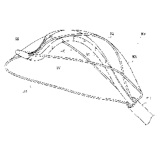
Turning now to the figures, Figures 1A-1D show a catheter apparatus 100, in
accordance with one or more example embodiments of the present disclosure.
Beginning
with Figure 1A, the apparatus 100 includes a filter device 110 that is
deployed via an outer
catheter 120, and which includes a filter material 111 such as a mesh, fabric
or other semi-
permeable material. A first shaft 130 is movable within the catheter 120, and
extends from a
proximal end to a distal end 132 near the filter device 110. A second
(backbone-type) shaft
140 passes through the first shaft 130, extending from a proximal end at 144
to a distal end
142, and is movable within the first shaft 130 for extending and retracting
the filter device
110 out of and into the first shaft, and for rotating the filter device when
deployed or
deploying. The filter material 111 is shown in an expanded state in Figure 1A,
while Figure
1B shows the filter material in a collapsed position/state in which the second
shaft 140 is
extended from the first shaft 130 to facilitate the collapse.
In this context, the catheter 120 can be inserted into a patient, such as via
a femoral
artery, and moved into a variety of vascular tissue locations, such as within
an aortic arch as
described herein and shown in other figures. Once in position, the first shaft
130 can be
extended out of the catheter 120 to deploy the filter device 110. The filter
device 110 is
connected to the first shaft near the distal end 132 and also connected to the
second shaft
near distal end 142. The second shaft is operative to control movement and
shape of the
filter device (e.g., extending the second shaft further out of the first shaft
collapses the filter
material 111, and partially retracting the second shaft into the first shaft
expands the filter
material). The first shaft is also operative to rotate the filter device 111
as needed.
The apparatus 100 may be implemented using one or more of a variety of
approaches, as consistent with the various embodiments discussed herein.
Figures 1B-1D
show various such embodiments as described in connection with Figure 1A.
Further, while
Figure 1A shows exemplary characteristics such as arc length, radius, tip
structure and
material types, these are by way of example and may be implemented using other
materials
and characteristics. For instance, certain embodiments are directed to
implementation of the
apparatus 100 for specific applications, such as for adult, child, infant or
animal patients, or
for implementation with specific types of vascular (other) tissue, with sizes
adjusted
accordingly.
Date Recue/Date Received 2020-09-04
11
In some implementations, the apparatus 100 is operative to facilitate fluid
exchange
via the catheter 120, such as for the delivery of drugs or other treatment, or
for aspiration.
By way of example, a fluid exchange (delivery/aspiration) connection 134 is
shown for
delivering fluid within the catheter and along the shaft first 130. Other
embodiments are
directed to fluid delivery internally via one or both of the first and second
shafts 130 and
140. One such embodiment is directed to the delivery of fluid through the
second shaft 140,
as applied at the proximal end 144.
Figure 1C shows a cross-sectional view "A-A" of the filter device 110 from
Figure
1A, with the filter material 111 being in an expanded position/state, while
Figure 1D shows a
cross-sectional view "B-B" of the filter 110 in the collapsed position/state.
In Figure 1C, the
second shaft/backbone 140 extends along a central portion of the filter
material 111, with a
perimeter structure 112 facilitating the expansion. The perimeter may, for
example, include
a hard wire type perimeter, or a portion of the filter material 111, which
facilitates expansion
and collapse of the filter material. By way of example, openings 146 in the
second shaft 140
may be implemented to deliver fluid between the proximal and distal ends of
the apparatus
100, such as to deliver anti-coagulating material to the filter material 111
to mitigate
collection of red blood cells and promote the flow of the cells through the
filter material. In
Figure 1D, the filter material 111 has been collapsed onto itself, with outer
perimeters on
opposing sides of the filter material being rolled over onto one another.
Figure 2 shows a filter apparatus 210, in accordance with another example
embodiment of the present invention. The filter apparatus 210 includes a
filter material 211
and a central backbone 240, and may be implemented in connection with the
components
shown and similarly-labeled in Figure 1A. For instance, the second shaft 140
may operate as
the backbone 240, with the filter apparatus 210 being implemented with
apparatus 110, and
the filter material 211 being expanded or collapsed as discussed above.
Figures 3A-3E show an implementation of a catheter apparatus, in accordance
with
one or more embodiments involving one or both of an apparatus and method
therefor. The
approaches shown in Figures 3A-3E may, for example, be implemented in
connection with a
catheter device similar to that shown in Figure 1A. Referring to Figure 3A, a
catheter
apparatus including an outer catheter 320, a first shaft 330 and a second
shaft 340 is inserted
at an aortic arch 300. The aortic arch is shown having respective arterial
openings 302, 304
and 306 that are desirably covered during procedures, such as a transcatheter-
aortic valve
replacement or implementation (TAVR/TAVI) procedure.
Figure 3B shows the catheter apparatus with a filter 310 therein deployed in a
collapsed state. Respective markers 346 (also shown in Figure 3A) and 347 are
used to
Date Recue/Date Received 2020-09-04
12
provide an indication of the position of the filter 310. In Figure 3C, the
catheter apparatus is
shown with the filter 310 deployed in an expanded state, covering openings
320, 304 and
306. In this expanded state, the filter 310 can be manipulated and conformed
to sidewalls of
the aortic arch 300, effectively covering the openings and forcing blood flow
into the
openings through a filter material of the filter 310. Once in place, the
filter 310 operates to
filter the blood flow, allowing passage of red blood cells while mitigating
the passage of
other particulates, such as may be dislodged or freed during a procedure. In
this context,
Figure 3D shows the catheter apparatus with the filter deployed in the
expanded state and
having particles captured therein.
In some implementations, the filter 310 includes a material that mitigates
collection
or coagulation of red blood cells on the filter, which may otherwise inhibit
the flow of blood
into the openings 302, 304 and/or 306. This may be implemented using an
approach such as
shown with openings 146 shown in Figure 1C, to deliver anti-coagulation
materials to the
filter material. In other implementations, the filter 310 includes material
that attracts and
traps/collects particulates, preventing the particulates from passing through
the filter and into
the openings 302, 304 and 306. Further, some implementations are directed to
the use of
both mitigation of the collection of red blood cells and attraction of other
particles.
After a procedure is complete, the catheter apparatus is retracted into the
outer
catheter 320 as shown in Figure 3E. The backbone 340 is manipulated to
collapse the filter
material, such as shown in Figures 1B and 1D, to trap the particles shown in
Figure 3D.
Once collapsed, the filter apparatus 310 is retracted into the outer catheter
320 via movement
of the first shaft 330 relative to the outer catheter 320. Once withdrawn into
the outer
catheter, the particles are trapped within both the filter 310 and the outer
catheter, and can be
safely removed.
Figures 4A-4F show another catheter type apparatus 400 at various stages of
deployment, in accordance with another embodiment. In Figure 4A, the apparatus
400 is
shown in an expanded state, with a perimeter wire 410 (and optional support
wire 420) being
extended relative to a shaft 430 and out of a sheath 440. For implementations
including the
support wire 420, some embodiments involve a coupling 414 between the
perimeter wire
410 and the support wire 420 (e.g., a solid wire, crimped wire pair or twisted
wire pair that
may provide a continuous wire connection between the perimeter wire 410 and
the support
wire 420). In this expanded state, a filter 412 is coupled to the perimeter
wire and operable
for conforming to a vessel wall while also passing fluid through openings in
the wall, such as
described above.
Date Recue/Date Received 2020-09-04
13
In Figure 4B, the apparatus 400 has been partially collapsed (e.g., to trap
particles in
the filter 412). In Figures 4C-4F, the filter 412 and perimeter wire 410 are
shown at various
stages of retraction into the sheath 440. Upon full retraction, particles
trapped in the filter
412 are contained within the sheath and removed (e.g., from within a blood
vessel) upon
removal of the catheter type apparatus 400.
Figures 5A-5C show portions of respective filter material, as may be
implemented in
connection with one or more embodiments. Example dimensions of respective
holes and
spacing therebetween are shown in each of the figures, by way of example with
the
understanding that various hole sizes and spacing are implemented to suit
different
embodiments. At Figure 5A, a filter material 510 is shown with holes
(including hole 512
labeled by way of example) with a relatively high density of holes and related
porosity. At
Figure 5B, a filter material 520 is shown with holes (including hole 522
labeled by way of
example) with a lower density than that shown in Figure 5A. Figure 5C shows a
filter
material 530 with holes (including hole 532 labeled by way of example) with a
density
between that shown in Figures 5A and 5B. These respective hole densities may
be
implemented with filters as described herein, such as with higher-density
holes provided
where the filter passes fluid, and with lower-density holes provided where the
filter
conforms to a vessel sidewall. As such, a varying degree of permeability of
filter material
can be attained.
Holes as shown in Figure 5 may be formed using one or more of a variety of
approaches. In some embodiments, the holes are drilled, with a thickness of
the filter
material set to accommodate such drilling. In other embodiments, a mesh or
woven type
material is used for the filter. In connection with these and other
embodiments, it has been
discovered that respective thicknesses of materials facilitate drilling while
mitigating issues
with regard to the passage of fluid, such as fluid including red blood cells.
One such
material that may be implemented in this regard is a polyurethane-on-paper
film, such as
ArgoMedTm or ArgoMedPLUSTm 18411 film available from Argotec of Massachusetts.
Figure 6 shows a filter 600 with respective regions having differing porosity
characteristics, in accordance with another example embodiment. Specifically,
regions
labeled area A, area B and area C are implemented with respective hole/opening
porosities.
In some embodiments, area A includes a filter material as shown in Figure 5A,
area B
includes a filter material as shown in Figure 5B, and area C includes a filter
material as
shown in Figure 5C.
Figure 7 shows a filter 700, in accordance with another example embodiment.
The
filter 700 may, for example, be used in a manufacturing process for forming a
filter coupled
Date Recue/Date Received 2020-09-04
14
to a perimeter wire. This coupling and arrangement of components facilitates
expansion of
the filter to conform to a vessel sidewall, and facilitates collapse of the
filter to trap particles
therein. In some implementations, the filter 700 is implemented in accordance
with the
hashed lines as shown, with an adhesive region and an uncoated region, with
dashed lines
representing masking for such a coating and a perimeter shown via solid line.
Figure 8 shows a proximal end portion of a catheter-type apparatus 800 for
insertion
into a patient, in accordance with another example embodiment. The apparatus
800 includes
a filter 805, and an outer sheath 810 having a backbone type shaft 820
extending from a
proximal end of the sheath. The backbone-type shaft 820 extends through the
outer sheath
to a distal end at which the shaft may be manipulated externally. Perimeter
wires 830 and
832 are connected to an end 822 of the shaft 820, and extend into the sheath
810 to the distal
end of the catheter, where the wires can also be manipulated externally.
Optional wires 840
and 842 are also shown, connected to the backbone type shaft 820, and operable
to provide
shape to the filter 805. The backbone operates to provide a "C" type shape
that facilitates
shaping of the filter. By way of example, the backbone is shown with openings
therein,
which may be used to pass fluid into or out of the area in which the apparatus
800 is used.
The following discussion refers to various embodiments involving a filter
apparatus
and directed to one or more of protecting, capturing, filtering, aspirating,
and diverting and
trapping embolic particulate matter from traveling freely within the vascular
arteries and the
associated side branches while continuing to allow blood to flow freely and
safely of emboli.
These embodiments may, for example, be implemented with those described above
and/or
shown in the figures, such as with the catheter-based apparatus of Figure 1
and/or the
approaches shown in Figures 3A-3E. The devices can also be implemented for
ease of
delivery, deployment, expansion, visualization under x-ray and angiography,
placement and
adjustment, and retrieval/retraction through a single access point. Further,
various
embodiments herein refer to a filter or other component such as a mesh or
fabric, which may
be implemented as the embolic protection/capture device (EPCD) and/or as part
thereof. As
such, various embodiments may be implemented using different approaches
described using
these and other terms, with other related terms.
The device delivery wire and mechanism itself can be made of various types of
metal, fabric and or plastic materials and a wide range of wire, porous
materials or mesh
sizes. The total overall length of the device may have a range of lengths from
as short as,
e.g., 60cm to 300cm or greater, in length with possible placement of
radiopaque markers at
proximal, distal, medial, and lateral points within and about the frame and
structure of the
device. The EPCD frame or primary structure may be constructed of a nitinol,
cobalt alloys,
Date Recue/Date Received 2020-09-04
15
stainless steels, various polymers, PTFE, polyurethane, various plastics, bio-
resorbable
materials or any combination thereof.
The frame itself has one or more of a variety of geometric designs and
mechanisms,
such as diamond, kite, oval, leaf, pear, or similar geometric shape having a
uniform sealing
frame and edges for secure wall apposition and arch anatomy or between one or
more points
of primary contact distally, laterally, superior, inferior, and proximally, as
may be
implemented in one or more embodiments. In some implementations, the proximal
origination of the frame evolves from one primary point of the delivery system
so that it is
easily deployed and recaptured. The shape of the distal points may be similar
to that of a
diamond or possibly two asymmetric elongated triangles or variation thereof,
and function in
a motion similar to how jaws open and close, opening and closing, edges
overlapping,
entrapping, or sealing or meeting flush, or some other opening and closing
mechanism. In
some implementations, the single backbone wire, hollow for transfer of wires
or solid for
support, with supporting frame and mesh forms the shape of one or more of an
oval, kite,
pear, or similar geometric shape and functions in a motion that would form and
seal (or
about seal) aspects within the anatomy of the aortic arch.
In one particular embodiment, a filter frame is as follows. The frame is from
2.5" to
6" in length, and the width in closed position is from .100" to .250." The
width when
expanded varies from .500" to 3.00" depending on anatomy the device is placed
into. In the
closed position (prior to expansion), the device fits into a 6-10fr delivery
sheath or greater.
The frame may be of a single layer of braided mesh, fabric or other porous
material, and may
include a double layer or multilayer design. The frame may have two layers of
wire or
plastic braid with a layer of material encapsulated between the two layers.
The frame may
be wire only for outer shape with braid, mesh or other porous material placed
over the top of
a skeletal frame, such as a kite structure with frame and material over it.
The device can be built in various configurations to suit particular
embodiments,
which may include one or more of: fixed wire tip, rapid exchange design, over
the wire
design, or a combination thereof. In some embodiments, the frame is all
Nitinol or other
metal, all plastic, or a combination of both. The radius will adjust to fit
Aortic Arch of
various anatomies. A center wire or wire/catheter with lumen operates as a
back-bone of the
device and allows the device to hold in top of aortic arch and have enough
strength to remain
in position under cardiac output flow and blood pressure conditions. This back-
bone will
also allow for the transfer of fluids, drugs, and other materials, such as for
injection or
aspiration. The devices herein can be made with multiple sizes accommodating a
wide range
of aortic arches, types, and/or small anatomy of an infant or adolescent.
Date Recue/Date Received 2020-09-04
16
The filter or porous membrane material of the EPCD device may be constructed
of
nitinol, cobalt alloys, polyurethane, stainless steels, various polymers,
PTFE, various
plastics, bio-resorbable materials or any combination thereof. For example,
polymer blends
such as a FEP/ePTFE (fluorinated ethylene propylene/expanded
polytetrafluoroethylene)
composite material may be implemented in this regard. The material of the
membrane and
the frame size itself would range in size and dimension to allow continuous
blood flow and
adequately cover the vessel walls in a concentric or eccentric fashion to
protect and cover the
major vessel branches and collateral side branches once deployed.
The filter or porous membrane deflects, detains, and or captures embolic
debris, and
may be made of a material that includes a drug coating such as heparin,
thrombolytic drugs
or anticoagulant drugs, and may include a material that attracts particulates
that are desirably
filtered. In some implementations, the backbone wire and mesh frame are ported
to facilitate
the delivery of drugs or other materials, such as anti-coagulants.
Other aspects are directed to stabilizing and securing a filter as described
herein in a
particular vascular anatomy, such as the aortic arch or other vascular tissue,
and may include
shapes relating to one or more of a wind sail, kite, or other geometric shape.
The geometric
shape of the material of the filters discussed herein can be implemented to
seal and configure
to the natural shape of a vessel wall as blood pressure and blood flow pump
through the
vessel, with porosity that facilitates ample blood flow both through the
filter into openings
secured as well as past the filter in bypassing the openings. This mechanism
and geometric
shape of the backbone wire or mesh frame may operate in a manner similar to
how wind
blows into a sail, parachute, kite or even the shape of a dome or half bubble,
circle, oval, or
ball, such that the mechanism presents a configuration which is curved,
uniform and adapts
to the walls of the vessel. In some implementations, the device takes
advantage of fluid
pressure to assist with placement and/or securement. The points of contact
allow enough
pressure to secure the filter in place and to incorporate wall apposition that
would create a
tight seal along and around the edges of the frame and ends of the device to
mitigate or
prevent emboli and/or thrombus from leaking/escaping behind or around the
circumference
and proximal or distal ends of the device and into unwanted vascular arteries
and anatomy.
In various embodiments, the backbone (the central beam or wire, tubing or
catheter
body) is made with a strength and shape that allows the device to be held
filutly against the
top of the Aorta. The capture filter, basket or frame is then expanded from
the back bone of
the device and can conform to various aortic shapes along with covering one or
more
branches in the area once in position. The device facilitates deployment with
torque,
pushing, and tracking of the device into desired position, prior to expanding
the capture
Date Recue/Date Received 2020-09-04
17
portion of the device. This will allow for position and control in placing the
device, which
can be done prior to picking up all the forces that will come when the basket
is expanded.
In some implementations, the backbone is shaped to conform to the top of the
aorta.
The front or distal portion of the device is specifically formed to hug
tightly or push against
the Aorta wall so that no blood flow can get between the device and the wall
that would
cause the device to be pushed away from the wall. The frame is shaped so that
the outer
edges of the frame where formed to push into the aorta.
In other embodiments, a filter frame and membrane distal and proximal ends
and/or
right and left edges can be collapsed to create a conical/funnel touching or
overlapping
configuration for capturing, aspirating, and filtering emboli in combination
with the delivery
and retrieval system, and continuing to allow for catheter use and exchange of
equipment.
The back bone and the distal and proximal ends of the device move
independently of each
other, when the back bone is pushed forward it causes the frame to expand into
a larger
radius. When the back bone is pulled back, it causes the frame to collapse and
the outer
edges of the frame are drawn in capturing anything that is in or on the inside
of the frame.
Various such embodiments are shown in the figures and in Appendix 1. For
instance, edges
may overlap when closed. Once closed, the device can then be pulled back into
the delivery
sheath with all the particulate still captured in the basket frame.
In some implementations, a frame is attached or fixed at the one end so
proximal and
distal ends can be moved relative to each other allowing expansion of the
filter and device.
This movement may facilitate sliding of the filter on a fixed deployment wire,
aiding in both
deployment of the device and the constraining of the filter/device for
removal. In some
implementations, radiopaque markers are distal, medial, and proximal and/or
where
appropriate to facilitate placement. The frame and wire itself may be
implemented as rapid
exchange, fixed tip or over-the-wire in design and mechanism. The backbone and
frame can
move independently of each other, the frame can be expanded when out of the
sheath or
closed down prior to being pulled into the sheath.
In some embodiments, a radiopaque (bumper and stopper) marker is located
approximately at the distal end of a wire to prevent the distal portion of the
frame from
sliding back out and off the wire. When the filter is constrained, the sliding
portion of the
device (frame) can be pulled back with the filter in closed position. Once the
device begins
to be deployed, the frame starts to slide back away from the stopper while
expanding into the
vessel. Wall apposition of the device can be controlled, secure, and
stabilized in an
atrumatic matter by the frame and filter membrane.
Date Recue/Date Received 2020-09-04
18
In some embodiments, the filter is preloaded into a sheath, such as a pin and
pull
sheath, or other deployment and retrieval sheath or catheter. It can be loaded
at time of use
or could pre-loaded into the proprietary delivery system (e.g., having an
outside diameter
of approximately 6 French or greater). The delivery sheath may be constructed
of a
proprietary braided or non-braided PTFE material or other material, with a
radiopaque tip
and long shaft approximately 75cm and 110cm or greater in length for adults,
with smaller
dimensions for children. The device and delivery wire may thus be implemented
with a
lock, stop, and stabilize feature to assure little if any migration of the
filter during the
introduction and removal of devices.
In some embodiments, the frame and design also functions to stabilize and
avoid
migration of the EPCD system. Further to the membrane geometric shape and
design, the
collapsible lateral sides, and/or distal and proximal ends can be
retrieved/collapsed to create
a funnel/filter/conical configuration for aspiration, capturing and filtering
emboli. Capturing
the EPCD device would also include a delivery sheath and catheter or a
secondary retrieval
system of equal or greater French size.
In some embodiments, the delivery and retrieval sheath have a pressure lumen,
with
room for other tools after the filter is deployed, to passed/introduce and
accessed to a target
site. Such tools may include, for example, diagnostic catheters, aspiration
catheters, or other
adjunctive devices. The frame of the EPCD may be implemented with a porous
material that
covers the frame, thereby allowing continuous blood flow, preventing and
avoiding
unwanted embolic particulate matter to travel into or freely within the
vascular vessels or
associated side branches. In some implementations, the porous material
captures embolic
particulate matter as small as 60 to 180 microns.
The filter size may include one or more sizes and numbers of wire (PPI ¨ Picks
Per
Inch), and may use porous fabric, polymer porous fabrics, and layers moved or
positioned
relative to each other to create different size porous/holes in the filter.
The frame of one or
more EPCDs as described herein may be either external of the filter or
interwoven within the
filter. The filter can either be positioned between the two braided layers or
attached to the
outer surface of the braid or frame. The EPCDs may include nitinol, stainless
steel or other
wire materials to include all kinds of wire sizes, multiple wires and PPI of
the wires. The
filter could also include a plastic mesh and/or fabric materials that are part
of a basket or
capture area of the device.
Based on different anatomies and applications, the EPCDs as described herein
could
be implemented using a broad-sized matrix, both in length of the frame and
diameters. For
instance, the frame length may vary from .5 cm up to 20 cm or greater, and the
diameter and
Date Recue/Date Received 2020-09-04
19
opening of the distal points may vary between 5 mm to 80 mm or greater. These
approaches
may allow for ample coverage of all arterial lumens of the greater arch
vessels or aorta if
necessary. Such approaches may be implemented to facilitate coverage of
various arch
classification types such as I, II, and III, and arch anomalies and variables
such as a Bovine
Arch.
The backbones/shafts described herein may be implemented using one or more of
a
variety of approaches. In some implementations, the backbone wire and mesh
frame are
operable to deflect in function so that the wire and mesh frame control the
arch height and
dimension of an EPCD, allowing the EPCD to fit various patient anatomy and
sizes. In
various embodiments, a backbone includes shapeable metal tubing, wire, or a
catheter type
shaft. The backbone holds the device tight against the top of the aorta, and
is shaped to hold
position in the aorta. The backbone facilitates in torque and positioning the
device, and
moves independently of the basket either on the proximal or distal end, which
facilitates
expansion and collapse of the filter. In some implementations, the backbone
wire and mesh
frame delivery wire proximal and distal connectors operate to move relative to
each other,
facilitating control of the width/size of the filter.
Various embodiments are directed toward protecting a patient from ischemic
stroke
during coronary and heart valve procedures by mitigating or blocking the
passage of embolic
particulate matter from entering the neurovascular arteries, and protecting
the peripheral
arteries and extremities. Other embodiments are directed to protecting
patients from embolic
induced ischemia in the peripheral vascular, coronary vascular or other
vascular beds. This
approach can be used in TAVI procedures but can also be used in any other
procedure that
requires distal protection.
Filter devices as discussed herein are implemented in one or more of a variety
of
manners. In some embodiments, a catheter-type filter device is placed via
trans-catheter,
trans-apical, or surgical cut down through most all vascular access vessels
such as the right
common femoral or left common femoral artery and/or brachial approach through
the left or
right subclavian arteries. The devices can be implemented as a temporary
device in
conjunction with a procedure that may dislodge or displace plaque, atheroma or
thrombus
that can travel within the vascular system. For instance, the devices and
approaches can be
used in the aorta and to protect the neurovasculature from ischemic stroke or
transient
ischemic attacks. Further to the proprietary frame and membrane design, the
lateral sides
and distal or proximal ends could be retrieved/collapsed to create a
funnel/filter/conical
shape configuration for capturing, aspirating, and filtering emboli traveling
into the lower
extremities.
Date Recue/Date Received 2020-09-04
20
In some implementations, a delivery device wire as described herein ranges
from
0.014 inch to 0.035 inch, or greater, with an integrated and designed frame
and structure that
may include a geometric/asymmetrical/symmetrical porous membrane. In various
embodiments, the geometrical and asymmetrical/symmetrical porous membrane is
implemented with a consistent spacing pattern, or with an inconsistent spacing
pattern
depending on the anatomy and the need to curve/collapse/deploy and retrieve
the device.
The number of cells and/or weaves and/or geometric spaces per device is varied
in some
embodiments, based on the amount of area needed to expand and cover with the
vascular
anatomy.
Various geometric patterns include spaces or cells with a porous material or
wire
mesh weave connecting them together such as a nitinol mesh or weave, stainless
steel mesh
or weave, a polymer mesh or weave, a PTFE mesh or weave, a plastic mesh,
polyurethane
mesh or weave or a combination thereof. The porous material is implemented
with a size
that facilitates passing of red blood cells and capture of embolic particulate
matter.
In some implementations, after gaining access via standard percutaneous
technique
or a cut down technique, an access needle is placed and a guide wire and short
sheath
introduced into a patient. A diagnostic wire is then exchanged and introduced.
A
diagnostic catheter is then introduced and the diagnostic wire removed. An
arterial gram is
taken to verify arterial and anatomical landmarks for proper device
positioning and
deployment. An exchange length wire is then introduced and the diagnostic
catheter
removed. A filter device as discussed herein is prepped, ready to be advanced
into the
vessels of the aorta and then positioned in and within the ascending aorta,
great aortic arch,
and descending aorta. The device (e.g., preloaded in a peel-away sheath, or
pin and pull
sheath, or retrieval and deployment sheath, or manually loaded) is then loaded
on the wire
either as a rapid exchange or over-the-wire system and introduced into the
sheath and
advanced to the end of the sheath that is currently positioned in the aorta.
The wire tip can
be made soft and shapeable to accommodate different anatomies and minimize any
vessel
trauma or breaking free of emboli. Once the device positioning is confirmed,
the sheath, the
pin and pull sheath, or proprietary retrieval and deployment sheath may be
removed from
while still in the original sheath.
At this point the EPCD device is ready for deployment. Using the radiopaque
positioning markers for orientation and making sure that the wire is oriented
on the greater
curve of the arch, as may be implemented in the following examples:
Example 1: Using the peel away sheath, a peel away portion of the sheath is
removed
and begin the sheath is pulled back with one hand keeping the EPCD wire
stable. Peeling
Date Recue/Date Received 2020-09-04
21
the sheath back will expose the EPCD and allow for the geometrical frame and
membrane
design to take shape and contour to the aortic arch.
Example 2: Using the Pin and Pull sheath, the sheath is pulled back while
keeping
the wire stable, to expose the filter and allow for the geometrical frame and
membrane
design to take shape and contour to the aortic arch.
Example 3: Using the retrieval and deployment sheath, the delivery system is
engaged following the delivery device steps which will expose the filter and
allow for the
geometrical frame and membrane design to take shape and contour to the aortic
arch.
Example 4: Using the manual loaded method, the device is loaded into a
delivery
sheath or catheter and pushed to position the device in place, followed by
similar steps as the
pin and pull method to expose the filter and allow for the geometrical frame
and membrane
design to take shape and contour to the aortic arch.
Once the procedure (e.g., coronary surgery, valve replacement surgery) is
completed,
the device can be removed. Any embolic particulate matter that was captured or
remaining
can be filtered, aspirated, and removed using and following the retrieval step
methods.
Depending on the size, length or diameter of the device, it may take a larger
sheath than the
original sheath; use of a proprietary retrieval system, or an aspiration and
extraction device
to remove any emboli prior to removing/retrieving the device.
Using a retrieval sheath, remove the original sheath and advance a larger
sheath into
the descending aorta up to the most proximal end and remove the dilator. Once
the dilator is
removed, advance the sheath over the first segment making sure that it is
collapsing into the
advancing sheath; continue until the entire device is inside the sheath. At
this point it is safe
to remove both the wire and sheath from the patient.
Various other embodiments as described herein may be implemented together with
other embodiments herein and/or with the provisional patent applications
referenced above.
Based upon the above discussion and illustrations, those skilled in the art
will readily
recognize that various modifications and changes may be made to the various
embodiments
without strictly following the exemplary embodiments and applications
illustrated and
described herein. For example, different types of materials may be used for
the various
components herein, and other manners in which to expand/collapse mesh-type
structures
with similar effect can be implemented. Additional shafts may be employed to
separately
move components of the filter material as discussed herein, such as by
employing respective
shafts to independently manipulate respective perimeters of the filter
material, to conform
the shape thereof. In addition, the various methods described herein may be
implemented
with different types of arteries, valves and tissue, as well as different
types of live beings.
Date Recue/Date Received 2020-09-04
22
Such modifications do not depart from the true spirit and scope of various
aspects of the
invention, including aspects set forth in the claims.
Date Recue/Date Received 2020-09-04