Note: Descriptions are shown in the official language in which they were submitted.
CA 02913190 2015-11-20
64869-3224
1
Method and system for preventing fouling of surfaces
TECHNICAL FIELD
The present disclosure relates to methods for preventing fouling, or commonly
referred to as anti-fouling, of surfaces and to devices for performing these
methods. The
disclosure specifically relates to methods and devices for anti-fouling of the
hull of ships.
BACKGROUND
Biofouling or biological fouling is the accumulation of microorganisms,
plants,
algae, and/or animals on surfaces. The variety among biofouling organisms is
highly diverse
and extends far beyond attachment of barnacles and seaweeds. According to some
estimates,
over 1700 species comprising over 4000 organisms are responsible for
biofouling. Biofouling
is divided into microfouling which includes biofilm formation and bacterial
adhesion, and
macrofouling which is the attachment of larger organisms. Due to the distinct
chemistry and
biology that determine what prevents organisms from settling, these organisms
are also
classified as hard or soft fouling types. Calcareous (hard) fouling organisms
include barnacles,
encrusting bryozoans, mollusks, polychaete and other tube worms, and zebra
mussels.
Examples of non-calcareous (soft) fouling organisms are seaweed, hydroids,
algae and biofilm
"slime". Together, these organisms form a fouling community.
In several circumstances biofouling creates substantial problems. Machinery
stops working, water inlets get clogged, and hulls of ships suffer from
increased drag. Hence
the topic of anti-fouling, i.e. the process of removing or preventing fouling
from forming, is
well known. In industrial processes, bio-dispersants can be used to control
biofouling. In less
controlled environments, organisms are killed or repelled with coatings using
biocides,
thermal treatments or pulses of energy. Nontoxic mechanical strategies that
prevent organisms
from attaching include choosing a material or coating with a slippery surface,
or creation of
nanoscale surface topologies similar to the skin of sharks and dolphins which
only offer poor
anchor points.
CA 02913190 2015-11-20
64869-3224
la
US 2013/0048877 pertains to a method and apparatus for anti-biofoulinu of a
protected surface, such as a ship hull, in liquid environments. An UV light
source is provided
close to optical coating and enters therein. Optical coating is bonded
proximate to a protected
surface of a structure, such as a ship's hull. Optical coating provides a
propagation path of
ultraviolet light in a direction parallel to surface. At any region along the
surface, which is the
surface of the optical coating UV-light is emitted in the direction away from
the protected
surface.
WO 2007/087710 pertains to a lighting system. The system comprises a light
guide wherein a side light-emitting element is positioned. The lement is
attached to a
substrate. A primary optics is coupled to the light-emitting element and
enables redirection of
the light sideways.
WO 98/00964 discloses backlight illumination devices of reduced thickness for
2D and 3D displays. A light guide may be in form of a light transmissive
rectangular substrate
such as a light transmissive slab. The slab includes two parallel opposed
surfaces, first surface
and second surface. Light sources arc located at the side's light guide. The
light may be
directed towards edges by appropriate reflectors which are coplanar with light
guide. Light
from the light source is captured by slab of light guide by refraction at the
end faces. By total
eternal reflection, light raise propagate in the slab. Lenticular lenses
collect the light and focus
it outside the light guide.
JP H11 278374 refers to the prevention of contamination of a dock inside wall
face. A contamination prevention means is provided with a photocatalyst
reaction body
arranged on the dock inside wall face and irradiated by ultraviolet or visible
light from the
sun. It is said that the photocatalyst reaction body is decomposed.
SUMMARY
CA 02913190 2015-11-20
WO 2014/188347 PCT/IB2014/061579
2
Biofouling on the hull of ships, as illustrated in Fig. 1, causes a severe
increase
in drag, and thus increased fuel consumption. It is estimated that an increase
of up to 40% in
fuel consumption can be attributed to biofouling. As large oil tankers or
container transport
ships can consume up to Ã200.000 a day in fuel, substantial savings are
possible with an
effective method of anti-biofouling.
Herewith an approach is presented based on optical methods, in particular
using ultra-violet light (UV). It is well-known that most micro-organisms are
killed, rendered
inactive or unable to reproduce with 'sufficient' UV light. This effect is
mainly governed by
the total dose of UV light. A typical dose to kill 90% of a certain micro-
organism is 10 mW-
hours per square meter, details are contained in the following paragraphs
regarding UV light,
and the associated Figures.
Ultraviolet light in general
Ultraviolet (UV) is that part of electromagnetic light bounded by the lower
wavelength extreme of the visible spectrum and the X-ray radiation band. The
spectral range
of UV light is, by definition between 100 and 400 nm (1 nm=10-9 m) and is
invisible to
human eyes. Using the CIE classification the UV spectrum is subdivided into
three bands:
UVA (long-wave) from 315 to 400 nm
UVB (medium-wave) from 280 to 315 nm
UVC (short-wave) from 100 to 280 nm
In reality many photobiologists often speak of skin effects resulting from UV
exposure as the weighted effect of wavelength above and below 320 nm, hence
offering an
alternative definition.
A strong germicidal effect is provided by the light in the short-wave UVC
band. In addition erythema (reddening of the skin) and conjunctivitis
(inflammation of the
mucous membranes of the eye) can also be caused by this form of light. Because
of this,
when germicidal UV-light lamps are used, it is important to design systems to
exclude UVC
leakage and so avoid these effects. In case of immersed light sources,
absorption of UV light
by water may be strong enough that UVC leaking is no problem for humans above
the liquid
surface.
Self evidently people should avoid exposure to UVC. Fortunately this is
relatively simple, because it is absorbed by most products, and even standard
flat glass
absorbs substantially all UVC. Exceptions are e.g. quartz and PTFE
(PolyTetraFluorEth(ypene). Again fortuitously, UVC is mostly absorbed by dead
skin, so
CA 02913190 2015-11-20
WO 2014/188347
PCT/IB2014/061579
3
erythema can be limited. In addition UVC does not penetrate the eye's lens;
nevertheless,
conjunctivitis can occur and though temporary, it is extremely painful; the
same is true of
erythemal effects.
Where exposure to UVC light occurs, care should be taken not to exceed the
threshold level norm. Figure 2 shows these values for most of the CIE UV
spectrum. In
practical terms, Table 1 gives the American Congress of Governmental and
Industrial
Hygienist's (ACGIH) UV Threshold Limit Effective Irradiance Values for human
exposure
related to time. At this time it is worth noting that radiation wavelengths
below 240 nm forms
ozone, 03, from oxygen in air. Ozone is toxic and highly reactive, hence
precautions have to
be taken to avoid exposure to humans and certain materials.
Duration of exposure per day Irradiance (uW/cm2)
8 hours 0.2
4 hours 0.4
2 hours 0.8
1 hour 1.7
30 minutes 3.3
minutes 6.6
10 minutes 10
5 minutes 20
1 minute 100
Table 1: permissible UVC exposures for humans according to ACGIH
Generation and characteristics of short-wave UV light
15 The most
efficient source for generating UVC is the low-pressure mercury
discharge lamp, where on average 35% of input watts is converted to UVC watts.
The
radiation is generated almost exclusively at 254 nm viz. at 85% of the maximum
germicidal
effect (Fig. 3). Philips' low pressure tubular flourescent ultraviolet (TUV)
lamps have an
envelope of special glass that filters out ozone-forming radiation, in this
case the 185 nm
mercury line. The spectral transmission of this glass is shown in Figure 4 and
the spectral
power distribution of these TUV lamps is given in Figure 5
For various Philips germicidal TUV lamps the electrical and mechanical
properties are identical to their lighting equivalents for visible light. This
allows them to be
operated in the same way i.e. using an electronic or magnetic ballast/starter
circuit. As with
CA 02913190 2015-11-20
64869-3224
4
all low pressure lamps, there is a relationship between lamp operating
temperature and output.
In low pressure lamps the resonance line at 254 nm is strongest at a certain
mercury vapour
pressure in the discharge tube.This pressure is determined by the operating
temperature and
optimises at a tube wall temperature of 40 C, corresponding with an ambient
temperature of
about 25 C. It should also be recognised that lamp output is affected by air
currents (forced or
natural) across the lamp, the so called chill factor. The reader should note
that, for some
lamps, increasing the air flow and/or decreasing the temperature can increase
the germicidal
output.This is met in high output (110) lamps viz. lamps with higher wattage
than normal for
their linear dimension.
A second type of UV source is the medium pressure mercury lamp, here the
higher pressure excites more energy levels producing more spectral lines and a
continuum
(recombined radiation) (Figure 6). It should be noted that the quartz envelope
transmits below
240 nm so ozone can be formed from air. Advantages of medium pressure sources
are:
= high power density;
= high power, resulting in fewer lamps than low pressure types being used in
the same application; and
= less sensitivity to environment temperature.
The lamps should be operated so that the wall temperature lies between 600 and
900 C and
the pinch does not exceed 350 C.These lamps can be dimmed, as can low pressure
lamps.
Further, Dielectric Barrier Discharge (DBD) lamps can be used. These lamps
can provide very powerful UV light at various wavelengths and at high
electrical-to-optical
power efficiencies.
The germicidal doses listed above can also easily be achieved with existing
low
cost, lower power UV LEDs. LEDs can generally be included in relatively
smaller packages
and consume less power than other types of light sources. LEDs can be
manufactured to emit
CA 02913190 2015-11-20
64869-3224
4a
(UV) light of various desired wavelengths and their operating parameters, most
notably the
output power, can be controlled to a high degree.
An basic idea underlying the present disclosure is to cover significant
amounts
of a protected surface to be kept clean from fouling, preferably the entire
protected surface,
e.g. the hull of a ship, with a layer that emits germicidal light, in
particular UV light.
Accordingly, herewith a method of anti-fouling of a protected surface as well
as a lighting module and a system for anti-fouling of a protected surface.
A method comprises providing anti-fouling light and emitting the anti-fouling
light in a direction away from a protected surface, wherein at least part of
the light is
distributed across a substantial part of the protected surface by an optical
mediumbefore being
emitted in the direction away from the protected surface. In embodiments, the
the method
comprises emitting the anti-fouling light from a substantially planar emission
surface of the
optical medium. In embodiments the method uses a light guide to distribute the
light across a
substantial part of the protected surface and comprises silicone material
and/or UV grade
silica material, in particular quartz. The method is preferably executed while
the protected
surface is at least partially submersed in a liquid environment.
A lighting module for anti-fouling of a protected surface comprises at least
one
light source for generating anti-fouling light and an optical medium for
distributing the
CA 02913190 2015-11-20
WO 2014/188347
PCT/IB2014/061579
A method comprises providing anti-fouling light and emitting the anti-fouling
light in a direction away from a protected surface, wherein at least part of
the light is
distributed across a substantial part of the protected surface by an optical
mediumbefore
being emitted in the direction away from the protected surface. In
embodiments, the the
5 method comprises emitting the anti-fouling light from a substantially
planar emission surface
of the optical medium. In embodiments the method uses a light guide to
distribute the light
across a substantial part of the protected surface and comprises silicone
material and/or UV
grade silica material, in particular quartz The method is preferably executed
while the
protected surface is at least partially submersed in a liquid environment.
A lighting module for anti-fouling of a protected surface comprises at least
one light source for generating anti-fouling light and an optical medium for
distributing the
anti-fouling light from the light source. The at least one light source and/or
the optical
medium may be at least partly arranged in, on and/or near the protected
surface so as to emit
the anti-fouling light in a direction away from the protected surface. The
lighting module is
adapted to preferably emit the anti-fouling light while the protected surface
is at least
partially submersed in an liquid environment. In an embodiment, the optical
medium is a
light guide comprises a silicone material and/or UV grade silica material.
The lighting module for anti-fouling of a protected surface may also be
provided as a foil for applying to the protected surface, the foil comprising
at least one light
source for generating anti-fouling light and a sheet-like optical medium for
distributing the
anti-fouling light across the foil. In embodiments the foil has a thickness in
an order of
magnitude of a couple of millimeters to a few centimeters In embodiments, the
foil is not
substantially limited in any direction perpendicular to the thickness
direction so as to provide
substantially large foil having sizes in the order of magnitude of tens or
hundreds of square
meters. The foil may be substantially size-limited in two orthogonal
directions perpendicular
to the thickness direction of the foil, so as to provide an anti-fouling tile;
in another
embodiment the foil is substantially size-limited in only one one direction
perpendicular to a
thickness direction of the foil, so as to provide an elongated strip of anti-
fouling foil.
The lighting module, whether arranged in, on and/or near the protected surface
or whether provided as a separate foil, comprises an emission surface for
emitting the anti-
fouling light from the optical medium into an evironment and a application
surface, opposed
the emission surface, for applying or arranging the lighting module to the
protected surface.
In a preferred embodiment the emission surface of the light module is
substantially planar so
as to avoid pits and indent which may become seeds of fouling and so as to
avoid bulges to
CA 02913190 2015-11-20
WO 2014/188347 PCT/IB2014/061579
6
limit the amount of drag caused by the structure when applied to the protected
surface. The
advantage of a substantially planar surface versus a surface comprising
indents and bulges or
having a substantial surface roughness is that it will be more difficult for
mircoorganisms to
adhere to a substantiall plane surface, especially in combination with drag
effects in a liquid
environment, than they would onto a rough surface or into pits comprises in
said surface The
term 'substantially planar' emission surface herein refers to a surface
masking or obscuring
the thickness of light sources and wiring connections embed in or attached to
the lighting
module The term 'substantially planar' may also refer to masking or obscuring
some
constructional uneveness of the protected surface, thereby even improving the
drag properties
of the protected surface in the liquid environment. Example of constructional
uneveness of
the protected surface are welds, rivets, etc. The term 'substantially planar'
can be quantified
as resulting in variations in the average thickness of the light modules of
less than 25%,
preferably less than 10%. 'Substantially planar' therefore not necessarily
requires a surface
roughness of a machined surface finish.
In a preferred embodiment the lighting module comprises a two-dimensional
grid of light sources for generating anti-fouling light and the optical medium
is arranged to
distribute at least part of the anti-fouling light from the two-dimensional
grid of light sources
across the optical medium so as to provide a two-dimensional distribution of
anti-fouling
light exiting the light emitting surface of the light module. The two-
dimensional grid of light
sources may be arranged in a chickenwire structure, a close-packed structure,
a rows/columns
structure, or any other suitable regular or irregular structure. The physical
distance between
neigboring light sources in the grid may be fixed across the grid or may vary,
for example as
a function of light output power required to provide the anit-fouling effect
or as function of
the location of the lighting module on the protected surface (e.g location on
the hull of a
ship). Advantages of providing a two-dimensional grid of light sources include
that the anti-
fouling light may be generated close to the areas to be protected with anti-
fouling light
illumination, and that it reduced losses in the optical medium or light guide
and that is
increasing homogeneity of the light distribution. Preferably, the anti-fouling
light is generally
homogeneously distributed across the emission surface; this reduces or even
prevents under-
illuminated areas, where fouling may otherwise take place, while at the same
time reducing
or preventing energy waste by over-illumination of other areas with more light
than needed
for anti-fouling.
In preferred embodiments, the light sources are UV LEDs. The at least one
UV LED or the grid of UV LEDs may be encapsulated in a liquid-tight
encapsulation. In
CA 02913190 2015-11-20
WO 2014/188347 PCT/IB2014/061579
7
embodiments the at least one UV LED or the grid of UV LEDs may be embedded in
the
optical medium. A plurality of UV LEDs may be organised in grid and
electrically connected
in a series/parallel chicken-wire structure (as will be explained later). The
LEDs and the
chicken-wire connections may be encapsulated in a light-transmissive coating
and attached to
the optical medium or directly embed in the optical medium. In other
embodiments the grid
of UV LEDs may be comprised in a layer of electronic textile which is embedded
in a resin
structure. In some embodiments the UV LEDs may be packaged LEDs, in which case
they
already may include an optical element to distribute the light emitted from
the LED package
across a wide emission angle. In other embodiment the UV LEDs may be LED dies,
typically
not comprising optical elements but being significantly thinner than packaged
LEDs. As an
example, LED dies could be picked and placed onto a surface of the optical
medium
(preferably the application surface, but the emission surface would do as well
because of the
small size of the components which will nearly not interfering with the light
emission
function of said surface), electrical wired via printing of conductive paste
and finally the
LED dies and wiring could be encapsulated with a thin layer/coating of the
optical medium
or any other backing layer for applying the lighting module to the protected
surface. Various
embodiments of embedded light sources allow the presented anti-fouling
technology to be
commercialized as a foil for applying on the hull of ships.
A system for anti-fouling of a protected surface may comprise a plurality of
lighting modules as disclosed herein for arranging on the protected surface so
as to provide
anti-fouling light over substantially the entire area of the protected
surface.
Silicone materials can provide optical transmission for UV light with little
loss
compared to other materials. This is in particular the case for shorter
wavelength light, e.g.
UV light with wavelengths below 300 nm. A particularly efficient group of
silicone materials
is, or at least comprises, so-called methyl silicones, according to the
general chemical
formula CH3[Si(CH3)20]1Si(CH3)3, with "n" indicating any suitable integral, as
customary in
organic chemistry. This type of silicone materials happens to exhibit
excellent UV
transmission properties with little losses, at least compared to other
silicone materials.
Further, silicone materials are flexible and resilient so that they are
robust, durable and
capable of withstanding compression such as due to bumps, collisions etc of
objects against
the surface, e.g. bumping of a ship against a quai. Further, deformation of a
ship's skin due to
temperature fluctuation, pounding by waves, ship's flexion over swell and
heave etc may be
accommodated. Also, silicone materials can be applied and formed over surface
structures:
welds, rivets, etc. in or on the surface. Silicone materials also tend to
adhere well to metals
CA 02913190 2015-11-20
WO 2014/188347 PCT/IB2014/061579
8
and paints so that a protective coating over the surface is formed. Visibly
transparent silicone
materials enable reading of underlaying markings (e.g. painted symbols)
covered by the
silicone material. Further, they are generally water repellent and may reduce
friction and
drag. On the one hand silicones can be made very smooth to reduce adherence of
biofouling
organisms to the layer and to reduce friction against flowing water, while on
the other hand
the material may be finely structured so as to mimic shark's skin which is
also known to
reduce friction in water at sufficient speed relative to the surrounding
water. It is noted that a
structured surface of an optical medium, in particular a light guide, can
cause breaking
conditions for total internal reflection and therewith cause coupling out of
light from the light
guide that was otherwise captured within and transmitted with total internal
reflection. Thus,
coupling out of light can be localised reliably.
UV grade silica has very low absorption for UV light and thus is very well
suitable as optical medium and light guide material. Relatively large objects
may be made
from using plural relatively small pieces or portions of UV grade silica
together and/or so-
called "fused silica", while retaining the UV-transmissive properties also for
the larger
object. Silica portions embedded in silicone material protect the silica
material. In such
combination the silica portions may provide UV transparent scatterers in an
otherwise
silicone material optical medium for (re-)distribution of the light trough the
optical medium
and/or for facilitating outcoupling of the light from a light guide. Also,
silica particles and/or
particles of other hard, UV translucent material may fortify the silicone
material. In particular
flake-shaped silica particles may be used, also in high density, of up to 50
%, 70 % or even
higher percentages of silica in silicone material may provides a strong layer
that can resist
impacts. It is considered that at least a part of the optical medoum or light
guide may be
provided with a spatially varying density of UV grade silica particles, in
particular flakes, at
least partly embedded in a silicone material, e.g. to vary optical and/or
structural properties.
Here, "flakes" denote objects having sizes in three cartesian directions,
wherein two of the
three sizes may mutually differ, however, each being significantly larger,
e.g. a factor 10, 20,
or significanly more, e.g. factors of 100's, than the third size.
In embodiments, in parts of the optical medium close to the emission surface
for emitting the anti-fouling light from the optical medium, the density of
the UV grade silica
particles in the silicone material may increase from within the optical medium
towards the
emission surface of the optical medium, so that at or near the emission
surface a relatively
high density of silica particles is provided. Although more or less spherical
and/or random-
shaped particles may be used, silica flakes of sub-millimeter length scales,
e.g. with typical
CA 02913190 2015-11-20
WO 2014/188347 PCT/IB2014/061579
9
sizes down to a few micrometers, may be arranged so close together that under
the influence
of very local forces, such as a point-impacts from sharp-tipped objects,
and/or localised
impacts from blunt objects, including scratches, tears etc, the flakes may
have some, if only
little, freedom of movement in the flexible silicone that they can slightly
rearrange
themselves, dissipating the impact energy and reducing damage to the light
guide as a whole.
Thus, a balance of properties can be struck that results in both a robust and
a somewhat
deformable layer, yet also providing the desired optical qualities. In an
embodiment the
proportion of silicone material in the optical medium varies gradually from
about 100% (i.e.
substantially pure silicone material) to below about 5% (mostly silica) from
one side of the
optical medium to an opposite side.
It is noted that particles, in particular flake-shaped particles, of other
material
than silica may be used, e.g. glass or mica. Such other materials may also
serve as scatterers
for the anti-fouling light. Mixtures of particles of different materials may
also be provided,
which may comprise mixtures of translucent, opaque and/or optically active
particles.
Compositions of such mixtures may vary across the light guide, e.g. to adjust
transmittivity
of the light guide for the anti-fouling light, in particular if in some
portions relatively large
amounts of poorly-transmitting particles are used.
For manufacturing the optical medium, a series of layers of silicone material
may be formed, each possibly having a different composition with regard to the
amount
and/or density of silica particles. The layers may be very thin and at least
some may be
applied with a wet-on-wet technique, i.e. providing the silicone material to
the layer in liquid
or gelatinous form that should harden to the desired layer, but wherein a
subsequent layer is
applied to an earlier layer before the earlier layer has fully hardened. Thus,
a good adhesion
between the layers is promoted and in the final product different layers may
be hardly to not
discernible and a gradual change in composition may be achieved. Different
layers may
suitably be formed and/or applied by spraying of the layer material. A layered
material may
be formed to any suitable thickness with good quality control. Note that the
optical medium,
which consitutes a substantial part of the lighting module's surface, may be
attached to the
protected surface in any suitable way, including gluing. Silicone materials
tend to exhibit
strong adhesion to ceramic, glassy and metallic materials and spraying or
smearing silicone
material is therefore a very suitable manner of forming and attaching the
optical medium to a
substrate. A sprayed and/or smeared optical medium can also readily be made in
different
desired shapes, e.g. following a water line, specific markings and/or surface
shapes. A
layering technique may also facilitate orienting particles in the silicone
material, e.g.
CA 02913190 2015-11-20
WO 2014/188347 PCT/IB2014/061579
arranging flakes generally parallel to the direction of expansion of the layer
and the surface
coated with the layer.
In another aspect of the lighting module, the optical medium comprises spaces,
e.g. channels which are filled with gas and/or clear liquid, e.g. water, for
guiding the light
5 therethrough and an associated method comprises distributing at least
part of the light
through such spaces in an optical medium. It is found that optical
transmission for UV light
through gaseous matter, in particular air, is generally significantly better
than transmission of
the light through a solid material which may, even if found translucent or
transparent by
some, exhibit absorption losses of up to several percents per millimeter.
Clear liquid provides
10 little scattering, may well transport UV light and may also provide
structural robustness of
cavities in the optical medium compared to filling the spaces with gas. Water,
most notably
fresh water, has been found to have a relatively high and suitable UV
transmittivity.
Contamination and/or UV absorption may be also and/or further reduced if
distilled,
deionised and/or otherwise purified water is used. Hence, it is considered
particularly
beneficial to transmit the light through a gas- and/or liquid-filled space.
For distribution of
the light across the protected surface, the gas- and/or liquid- filled space
should preferably be
well defined and channels may be provided in a optical medium. Light that
eventually strikes
walls of the channels can enter the optical medium and be emitted from the
optical medium
in a direction from the protected surface and into the liquid environment to
provide the anti-
fouling light. An optical medium in which the air channels are defined that is
itself well
transparent to the anti-fouling light further assures that if the optical
medium would leak and
the liquid medium enters the optical medium, generated anti-fouling light
would still be
appropriately transmitted through the optical medium. Channels may comprise
varying
diameter. Localised channel portions or pockets may be provided by wall
portions defining
and encapsulating separate volumes (much) bigger than the respective wall
portions' sizes
and/or thicknesses, e.g. similar to the packaging product sold under the brand
name "Bubble
Wrap".
In a particular embodiment, such gas- containing optical medium comprises a
silicone material defining the gas and/or liquid-filled channels and/or other
spaces; silicone
materials may well be shaped to define intricate structures. Further
advantages of silicone
materials, with or without additional objects such as silica particles have
been set out above.
In an embodiment, the channels and/or other spaces are provided by forming
two opposing layers of silicone material kept separated at desired distances
with wall
portions and/or pillars of silicone material creating a distance, e.g. an air
gap between the
CA 02913190 2015-11-20
WO 2014/188347 PCT/IB2014/061579
11
layers. Such wall portions and/or pillars may serve as scattering centres for
(re-)distributing
the light through (the channels in) the optical medium and/or for guiding
light from the gas-
and/or liquid filled space(s) into the silicone material. This facilitates
localising emission of
the light from the optical medium into the liquid environment where the anti-
fouling light is
to be put to use.
At least part of the anti-fouling light emitted by the one or more light
sources
may be spread in a direction having a component substantially parallel to the
protected
surface, or substantially parallel to the application surface of the foil when
the light moduled
is provided as a foil. This facilitates distributing the light over
significant distances along the
protected surface, or the application surface of the foil, which assists in
obtaning a suitable
intensity distribution of the anti-fouling light.
A wavelength conversion material may be comprised in the optical medium
and at least part of the anti-fouling light may be generated by photo-exciting
the wavelength
conversion material with light having a first wavelength causing the
wavelength conversion
material to emit the anti-fouling light at another wavelength. The wavelength
conversion
material may be provided as an upconversion phosphor, quantum dots, nonlinear
media such
as one or more photonic crystal fibers etc. Since absorption and/or scattering
losses in the
optical medium for light of different, mostly longer, wavelengths than UV
light tend to be
less pronounced in optical media, it may be more energy-efficient to generate
non-UV light
and transmit that through the optical medium and to generate UV anti-fouling
light at or near
the desired location of use thereof (i.e. emission form the surface into the
liquid
environment). Also, or alternatively, the at least one light source may
comprise at least one of
an LED or OLED, a DBD lamp and/or a metal vapour lamp (e.g. low pressure
mercury
vapour lamp). Suitable anti-fouling light is in the wavelength range of UV or
blue light from
about 220 nm to about 420 nm, in particular at wavelengths shorter than about
300 nm, e.g.
from about 240 nm to about 280 nm.
In embodiments, the optical medium comprises a light spreader arranged in
front of the at least one light source for generating anit-fouling light for
spreading at least part
of the anti-fouling light emitted by the at least one light source in a
direction having a
component substantially parallel to the protected surface. An example of a
light spreader may
be a 'opposite' cone arranged in the optical medium and position opposite the
at least one
light source, where the opposite cone has a surface area with a 45 angle
perpendicular to the
protected surface for reflecting light emitted by the light source
perpendicular to said surface
in an a direction substantially parallel to said surface. In embodiments the
optical medium
CA 02913190 2015-11-20
64869-3224
17
comprises a light guide arranged in front of the at least one light source for
generating the
anti-fouling light, the light guide having a light coupling-in surface for
coupling in the anti-
fouling light from the at least one light source and a light coupling-out
surface for coupling-
out the anti-fouling light in a direction away from the protected surface; the
light guide
comprising a light guide material having a refractive index higher than the
refractive index of
the liquid environment such that at least part of the anti-fouling light is
propagated through the
light guide via total internal reflection in a direction substantially
parallel to the protected
surface before being out-coupled at the out-coupling surface. Some embodiment
may
comprise an optical medium which combines a light spreader and a light guide,
or integrated
light spreading features with light guiding features into the optical medium.
In embodiments,
the light spreader and/or light guide is coated onto the protected surface. In
other
embodiments, the light spreader and/or light guide is provided in the form
factor of a foil for
appluying onto a protected surface.
An embodiment of a system for preventing fouling may comprise:
- a series of UV LEDs for generating anti-fouling light;
a light spreader for spreading the anti-fouling light from the LED point
sources
across the protected surface; and
a light guide for further guiding/spreading the anti-fouling light can be
spread
across the surface, the light guide comprising a tin layer of silicone
material transparant to UV
light, with or without silica particles or one or more silica coverered
portions.
When substantially the entire protected surface is covered with an anti-
fouling
light emitting optical medium, it substantially reduces the growth of micro-
organisms on this
medium. As the micro-organisms are killed on the emission surface of the
optical medium, the
hull is continuously cleaned through the water flow along the hull which
transports the debris
away from the ship and micro-organisms do not stand a chance of fouling on the
hull.
The anti-fouling light may be in the UV or blue wavelength range from about
220 nm to about 420 nm, preferably about 260 nm.
CA 02913190 2015-11-20
64869-3224
13
According to one aspect of the present invention, there is provided a method
of
anti-fouling of a protected surface comprising, while the protected surface is
at least partially
submersed in a liquid environment, in particular an aqueous or oily
environment: providing an
anti-fouling light; providing an optical medium in close proximity to the
protected surface, the
optical medium having a emission surface; distributing at least part of the
anti-fouling light
through the optical medium in a direction substantially parallel to the
protected surface; and
emitting the anti-fouling light from the emission surface of the optical
mediumin a direction
away from the protected surface, wherein the anti-fouling ligh is emitted by
at least one light
source, that the at least one light source comprises at least one UV LED
embedded in the
optical medium and that the emission surface is a substantially planar surface
masking or
obscuring a thickness of the at least one light source and wiring connections
embedded in a
lighting module.
According to another aspect of the present invention, there is provided a
lighting module for anti-fouling of a protected surface comprising: at least
one light source for
generating an anti-fouling light; an optical medium for distributing at least
part of the anti-
fouling light through the optical medium in a direction substantially parallel
to the protected
surface, the optical medium comprising an emission surface for emitting the
distributed anti-
fouling light in a direction away from the protected surface when the lighting
module is
arranged on the protected surface, wherein the at least one light source for
generating an anti-
fouling light comprises at least one UV LED embedded in the optical medium and
that the
emission surface is a substantially planar surface masking or obscuring a
thickness of the at
least one light source and wiring connections embedded in the lighting module.
A system for anti-fouling of a protected surface may be provided, the system
comprising: a plurality of light sources for emitting an anti-fouling light,
the plurality of light
sources arranged in a two-dimensional grid on or in close poximity to the
protected surface
and arranged to emit anti-fouling light in a direction substantially parallel
to or substantially
away from the protected surface; a light spreader arranged in front of the
plurality of light
sources for spreading at least part of the anti-fouling light emitted by least
one light source of
the plurality of light sources in a direction having a component substantially
parallel to the
CA 02913190 2015-11-20
64869-3224
13a
protected surface; and/or a light guide arranged in front of the plurality of
light sources, the
light guide having a light coupling-in surface for coupling in the anti-
fouling light from at
least one light source of the plurality of light sources and a light coupling-
out surface for
coupling-out the anti-fouling light from the light guide in a direction away
from the protected
.. surface; the light guide comprising a light guide material having a
refractive index higher than
the refractive index of the liquid environment such that at least part of the
anti-fouling light is
propagated through the light guide via total internal reflection in a
direction substantially
parallel to the surface before being out-coupled at the out-coupling surface;
wherein the light
spreader and/or the light guide is coated or sprayed onto the plurality of
light source and the
protected surface.
It is an advantage of the presently provided solutions that the micro-
organisms
are not killed after having adhered and rooted on the fouling surface, as is
the case for known
poison dispersing coatings, but that the rooting of micro-organisms on the
fouling surface is
prevented. It is more efficient to actively kill micro-organism right before
or just after they
contact the fouling surface, compared to a light treatment to remove existing
fouling with
large micro-organism structures. The effect may be similar to the effect
created by using
nano-surfaces that are that smooth that micro-organism cannot adhere to it.
Because the low amount of light energy required for killing the micro-organism
in the initial rooting stage, the system may be operated to continuously
provide an anti-fouling
light across a large surface without extreme power requirements.
A grid of LEDs creating a lighting surface may be provided with energy
harvesting means such as for example embedded solar cells, small turbines
operating in the
water, piezoelectric elements operating on pressure waves, etc.
Some advantages of the presently provided technology include the retention of
clean surface, Reduction of the cost of corrosion treatment, reduced fuel
consumption for
ships, reduced maintenance time for hulls, educed CO) emission, reduce the use
of toxic
substances in the environment, etc. A substantially planar and smooth light
emission surface
further has the advantage of not adding drag by itself and can even further
reducing drag by
CA 02913190 2015-11-20
64869-3224
13b
burying existing uneveness (rivets, welds, etc.) of the protected surface
underneath the optical
medium.
The features disclosed in the context of a lighting module described in the
present disclosure may also have a conesponding process step in the method for
anti-fouling
of a protected surface and vice versa, without explicitely being mentioned in
the description.
Corresponding features will generally produce the same technical effect.
The disclosed method and lighting module can be applied to prevent fouling on
hulls of ships, but they are applicable to all marine objects including
stationary (pipes, marine
stations etc.) and/or moving marine objects (submarines etc.). The disclosed
anti-fouling
solution may also be applied to objects operating in waterways, canals or
lakes and for
example also to aquariums.
BRIEF DESCRIPTION OF TI IF DRAWINGS
Fig. 1 shows a ships hull suffering from fouling;
Fig. 2 is a graph showing UV Light Threshold Limited Values (TLV)
according to the American Congress of Governmental and Industrial Hygienist's
(ACGIH);
Fig. 3 is a graph showing a germicidal action spectrum for different
biological
materials as a function of light wavelength;
Fig. 4 is a graph showing a transmission spectrum for different types of
glass;
Fig. 5 is a bar graph showing the relative spectral power distribution of
typical
Philips low pressure tubular fluorescent ultraviolet (TUV) lamps;
Fig. 6 is a bar graph showing the relative spectral power distribution of
Philips
medium pressure discharge lamps (HOK and HTK types);
Fig. 7 is a schematic cross section view of a light module with a light guide;
Fig. 8 shows a general concept of light guiding used in embodiments;
CA 02913190 2015-11-20
WO 2014/188347 PCT/IB2014/061579
14
Figs. 9(a)-9(b) show a realised planar light guide embodiment;
Figs. 10(a)-10(b) show wedge shaped light guide embodiments;
Figs. 11(a)-11(b) show direct-lit light guide embodiments;
Fig. 12 shows an embodiment comprising a redistribution reflector and a
wavelength conversion material;
Fig. 13 shows a light guide comprising gas-flied channels;
Fig. 14 shows an embodiment comprising distributed embedded flakes.
Fig. 15 shows an embodiment of a chicken-wire grid.
DETAILED DESCRIPTION OF EMBODIMENTS
While the disclosure has been illustrated and described in detail in the
drawings and foregoing description, such illustration and description are to
be considered
illustrative or exemplary and not restrictive; the disclosure is not limited
to the disclosed
embodiments. It is further noted that the drawings are schematic, not
necessarily to scale and
that details that are not required for understanding the present invention may
have been
omitted. The terms "upward", "downward", "below", "above", and the like relate
to the
embodiments as oriented in the drawings, unless otherwise specified. Further,
elements that
are at least substantially identical or that perform an at least substantially
identical function
are denoted by the same numeral.
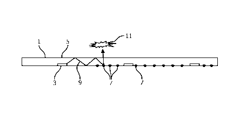
Fig. 7 shows as a basic embodiment a cross section of a lighting module 1
comprising a plurality of light sources 3 (here: side-emitting LEDs, wherein
the light is
emitted primarily from the side of the LED, and more or less parallel to the
surface)
encapsulated in a liquid-tight optical medium 5 to guide at least part of the
light 9 emitted
from the light sources 5 via total internal reflection through the optical
medium, which
optical medium is further provided with optical structures 7 to scatter light
9 and guided the
light 9 out of the optical medium 5 towards an object 11 to be targeted with
the light (a
biofouling organism). The optical medium 5 generally extends in two dimensions
significantly further than in the third dimension so that a two-dimensional-
like object is
provided. Optical structures 7 to scatter light 9 may be spread in one or more
portions of the
optical medium material, possibly throughout all of it, wherein in such
portions the distribion
may be generally homogeneous or localised. Scattering centres with different
structural
properties may be combined to provide, besides optical, also structural
characteristics, such
as resistance to wear and/or impact. Suitable scatterers comprise opaque
objects but largely
CA 02913190 2015-11-20
WO 2014/188347 PCT/IB2014/061579
translucent objects may be used as well, e.g. small air bubbles, glass and/or
silica; a
requirement is merely that a change in refractive index occurs for the
wavelength(s) used.
The principle of light guiding and spreading light over a surface is well-
known
and widely applied in various fields. Here, the principle is applied to UV
light for the purpose
5 of anti-fouling. It is noted that the idea of making a surface, e.g. the
hull of a ship self-lit with
UV is a clearly different solution than the current and well established anti-
fouling solutions
which rely on smooth coatings, chemicals, cleaning, software to control the
ship speed, etc.
Total internal reflection is one way of transmitting light through an optical
medium, which is then often referred to as a light guide. To maintain the
conditions for total
10 internal reflection, the index of refraction of the light guide should
be higher than that of the
surrounding medium. However, the use of (partly) reflecting coatings on the
light guide
and/or use of the reflective properties of the protected surface, e.g. the
hull of a ship, itself
can also be used to establish the conditions for guiding the light through the
optical medium.
In some embodiments the optical medium may be positioned relative to the
15 protected surface, e.g. the hull of a ship, such that a small air gap is
introduced between the
optical medium and the protected surface; UV light may travel even better ¨
with less
absorption ¨ in air than in an optical medium, even when this optical medium
is designed as a
light guiding material. In other embodiments gas-filled channels, e.g. air
channels, may be
formed within silicone material. An array of separate gas-filled pockets may
also be
provided, e.g. in a regular pattern like a rectangular or honeycomb-pattern or
in an irregular
pattern. Instead of gas (e.g. air) filling, channels and/or pockets may be at
least partly filled
with a UV-transmissive liquid, e.g. fresh and/or purified water. In case a
protected surface
that is covered with such optical medium is subject to impact, e.g. a ship
hitting a dockside,
small pockets may soften, redistribute the impact energy and hence protect the
surface,
wherein liquid-filled pockets may be robuster under deformation than air-
pockets which may
more easily burst open.
As most materials have a (very) limited transmittance for UV light, care has
to
be taken in the design of the optical medium. A number of specific features
and/or
embodiments, which are dedicated for this purpose are listed in the following:
- A relatively fine pitch of low power LEDs can be chosen, to minimize the
distance light has to travel through the optical medium.
A 'hollow' structure can be used, e.g. a silicone rubber mat with spacers that
keep it a small distance away from the protected surface. This creates air
'channels', through
which the UV light can propagate with high efficiency (air is very transparent
for UV). Use
CA 02913190 2015-11-20
WO 2014/188347 PCT/IB2014/061579
16
of gas filled channels provided by such structures allows distributing the UV
light over
significant distances in a optical medium of material that would otherwise
absorb the UV
light too strongly to be useful for anti-fouling. Similarly, separate pockets
may be formed.
A special material can be chosen with high UV transparency, like certain
silicones or UV grade (fused) silica. In embodiments, this special material
can be used only
for creating channels for the light to propagate the majority of the distance;
a cheaper/more
sturdy material can be used for the rest of the surface.
Further embodiments are disclosed in the accompanying drawings, wherein a
main issue is to illuminate a large surface with anti-fouling light,
preferably UV light, yet
using point light sources. A typical concern is spreading of the light from
point sources to
surface illumination. In more detail.
The protected surface area of a typical container ship is ¨10.000 m2.
Atypical LED source has an area of ¨ 1 mm2. This is 1010 smaller.
Taking the required power levels into account, about 10 LEDs per m2 may be
required
This means light has to be spread from 1 LED over ¨ 1000 cm2
As another boundary condition is taken that the solution should be thin (order
of magnitude: 1 cm), e.g. for reasons such as:
To be able to add the solution as a 'coating' to a ship
To not increase drag due to an increased cross section size of the ship
To keep (bulk) material costs limited.
The use of an optical medium, in particular a generally planar light guide is
therefore provided. Typical dimensions of a light guide are a thickness of
about 1 mm to
about 10 mm. In the other directions, there is no real limit to the size, from
an optical point of
view; in particular not if plural light sources are provided so that decay of
light intensity
throughout the light guide due to partial outcoupling of light and possibly
(absorption) losses
are countered.
Here, it is considered that similar optical challenges apply as with the
design
of LCD TV backlights, although emission light intensity uniformity is less
stringent in anti-
fouling than with LCD TV backlights. Fig 8 shows a lighting module 1 with
light sources 3
and a light guide 5 with an additional top layer 13. Figs. 9A-9B show
practical examples of
the principle illustrated in Fig. 8 and show a lighting module 1 with LED
sources 3 which are
positioned along the edge 15 of a light guide 5 and which inject light into
the light guide 5. A
pattern of scatterers e.g. white dots of paint, or small scratches/dents
extract the light in
CA 02913190 2015-11-20
WO 2014/188347
PCT/IB2014/061579
17
appropriate places, here generally uniform (Fig. 9B), so that a desired, e.g.
generally
homogeneous, illumination distribution of the environment is achieved.
Fig. 10(a) shows a LCD TV backlight arrangement wherein a wedge-shaped
light guide 5(a) is employed wherein the light from a light source 3 is
injected into the light
guide 5(a) from the side. The light guide 5(a) is arranged with a pattern of
scattering objects
7, such as dots of paint or scratches, on a reflective substrate 17 A wedge
shape causes more
of the light to be extracted towards the tip end. The prism sheets 19 and LCD
panel 21 that
orient polarisation states of the light and generate visible light colours are
feature that can be
omitted in an anti-fouling context..
Fig. 10(b) shows another wedge shaped light guide 5(b) which is provided
itself with a structured side so as to scatter and redistribute light within
and out of the light
guide 5(b).
Both the plane light guide and wedge-shaped light guide share the principle of
guiding light along a substantial distance substantially parallel to the
emission surface. The
alternatives shown in Fig. lla-11(b) (see below) are known as a direct-lit
optical medium;
here one or more LEDs and/or other light source(s) is present behind a screen
e.g. a diffuser
and emit light directly towards the object to be illuminated, e.g. a
biofouling organism.
In a side-lit optical medium, often referred to as a light guide, such as
those
shown in Figs.8-10(b) a side of the optical medium is illuminated from one or
more light
sources relatively strongly and further away from the light source(s) the
light intensity within
light guide is generally more homogeneous, possibly governed by scatterers
(Figs. 9(a)-9(b)).
In short, a difference betweem side-lit or direct¨lit concepts is that in
direct-lit
situations the light travels no substantial distance parallel to the emission
surface As a result,
the light intensity is usually much higher directly in front of the light
sources. No real
.. distribution of light is achieved. Thus, in a direct-lit solution a larger
intensity variation may
be expected between areas directly in front of the light source(s) and area
aside thereof.
Figs. 11(a) and 11(b) show lighting modules 101(a), 101(b) in cross section
view (cf Fig. 7) comprising light sources 3 and optical medium 105 (a), 105(b)
having an
emission surface 23. The wavy line "I(a)" and "I(b)", respectively, show the
light intensity
profile emitted from the emission surface and illustrate that a thicker
optical medium 105(b)
(Fig. 11(b)) will 'automatically' provide a better light uniformity on the
emission surface 23
than a thinner optical medium 105(a) (Fig. 11(a)) of otherwise identical
construction.
However, in the present case such relative intensity variations need not be of
much concern. Further, direct lit arrangements potentially also have
capability of controlling
CA 02913190 2015-11-20
WO 2014/188347 PCT/IB2014/061579
18
local intensity variations, which may also be utilised for providing both
temporal and spatial
intensity variations. Thus, the optical structure provided herewith is
relatively simple. As a
rule of thumb, for a high level of emission light intensity, the thickness of
a optical medium
in a direct-lit configuration is generally about equal to the LED pitch. If
the LED pitch is
10 cm, this rule of thumb might lead to an optical medium that is about 10 cm
thickness,
which is thicker than desired. However, the light emission uniformity
requirements for the
presently intended purpose of anti-fouling do not have to meet 'substantially
uniform
lighting' requirements and hence a thinner layer may be used in combination
with such LED
pitch.
Additional ideas and solutions exist to obtain a better uniformity in a
thinner
optical structure, such as introduction of scatters and/or reflectors or other
light spreaders
directly in front of one or more light sources.
Fig. 12 shows (left hand side) inclusion of a light spreader in the foim of a
reflective cone 25 in the optical medium 5 with an apex towards the light
source 3. This
directs the light 9 in a direction having a component substantially parallel
to the surface 27 to
be protected against fouling. If the cone 25 is not fully reflective nor
opaque, some light from
the light source will pass through it and creation of shadows leading to
reduced or ineffective
anti-fouling is prevented.
Further, Fig. 12 shows (right hand side) a wavelength conversion material
which is comprised in the optical medium 5. The illustrated embodiment is
configured to
generate at least part of the anti-fouling light by photo-exciting the
wavelength conversion
material with light from a light source 30 with light 31 having a first
wavelength causing the
wavelength conversion material to emit anti-fouling light 9 at another
wavelength from the
optical medium 5 into the environment E. The distribution of wavelength
conversion material
in optical medium 5 may be spatially varying, e.g. in accordance with
(expected) intensity
distributions of (different wavelengths of) light in the optical medium 5.
Fig. 13 shows an optical medium205 comprising a first layer 233, a second
layer 235 with a plurality of walls 237 and pillars 238 in between separating
the first and
second layers 233, 235 and creating gas-filled channels 239. The optical
medium 205 may be
used just as any of the other optical mediums shown herein.
Fig. 14 shows a portion of an object 300 to be protected against biofouling,
comprising an object surface 301, e.g. a ship hull, provided with an optical
medium 302
comprising embedded flake-shaped particles 303. (In the drawing, the light
sources are
CA 02913190 2015-11-20
WO 2014/188347
PCT/IB2014/061579
19
omitted.) The flakes 303 are distributed generally parallel to each other and
with increasing
density from the object surface 301 outwards to an emission surface 304.
Fig. 15 shows a chicken-wire embodiment where UV LEDs 3 are arranged in
a grid and connected in a series of parallel connections. The LEDs can be
mounted at the
nodes as shown in bottom left of Fig. 15 either through soldering, glueing or
any other known
electrical connection technique for connecting the LEDs to the chicken wires
4. One or more
LEDs can be placed at each node. DC or AC driving can be implemented. In case
of DC, the
LEDs are mounted as shown at the bottom right (a) of Fig. 15. If AC is used,
then a couple of
LEDs in anti parallel configuration is used as shown at the bottom right (b)
of Fig. 15. The
person skilled in the art knows that at each node more than one couple of LEDs
in anti
parallel configuration can be used. The actual size of the chicken-wire grid
and the distance
between UV LEDs in the grid can be adjusted by stretching the harmonica
structure. The
chicken-wire grid may be embed in an optical medium wherein optionally a
parallel grid of
scattering features are provided as illustrated in Fig. 12.
Besides anti-fouling application of hulls of ships, the following alternative
applications and embodiments are envisioned:
The disclosure can be applied to a wide variety of fields. Almost any object
coming into contact with natural water, will over time be subject to
biofouling. This can
hinder e.g. water inlets of desalination plants, block pipes of pumping
stations, or even cover
the walls and bottom of an outdoor pool. All of these applications would
benefit from the
presently provided method, lighting modules and/or system, i.e. an effective
thin additional
surface layer, which prevents biofouling on the entire surface area.
Although UV light is the preferred solution, other wavelengths are envisaged
as well. Non-UV light (visible light) is also effective against biofouling.
Typical micro-
organisms are less sensitive to non-UV light than to UV light, but a much
higher dose can be
generated in the visible spectrum per unit input power to the light sources.
UV LEDs are an ideal source for thin light emitting surfaces. However, UV
sources other than LEDs can also be used, such as low pressure mercury vapour
lamps. The
form factor of these light sources are quite different; mainly the source is
much bigger. This
results in different optical designs, to 'distribute' all the light from a
single source over a
large area. The concept of light guiding as discussed herein does not change
though. Further,
a significant contribution of light in desired wavelengths and/or wavelength
combinations
may be produced.
CA 02913190 2015-11-20
WO 2014/188347 PCT/IB2014/061579
Instead of using a thin layer that emits UV light outward in a direction away
from the protected surface in order to avoid bio-fouling, biofouling could
potentially also be
removed by applying UV light from the outside in the direction of the
protected surface. E.g.
shining a UV light onto a hull or surface comprising a suitable optical medium
as described.
5 Thus, a single optical medium emitting anti-fouling light in directions
to and away from
protected surfaces may be even more efficient..
The concepts are not restricted to the above described embodiments which can
be varied in a number of ways within the scope of the claims. For instance,
using light, in
particular UV light as an anti-biofouling means can provide an interesting
opportunity in
10 other fields. It is unique in the sense that continuous "24/7"
'protection' can be provided,
over a large area. The application is especially interesting for the hull of
ships, but can also
be applied in swimming pools, water treatment plants, etc. Instead of water,
biofouling may
occur and be treated in other liquid environments, e.g. oils, brines and/or
liquids in other
environments including food industry.
15 Elements and aspects discussed for or in relation with a particular
embodiment
may be suitably combined with elements and aspects of other embodiments,
unless explicitly
stated otherwise.