Note: Descriptions are shown in the official language in which they were submitted.
CA 02913324 2015-11-24
1
Screw
The invention relates to a screw, in particular a wood screw, having the
features of the
preamble of claim I.
Screws, in particular wood screws, in general have the function to attach at
least two
components, which components consist, e.g., of wood or a wood-like material.
Wood screws
are predominantly screwed into wood components, wherein they themselves will
cut an
appropriate counter-thread. A complementary counter-piece such as, e.g., a nut
having an
internal counter-thread, which usually is required for securing metal screws,
does not exist
with wood screws. Such wood screws usually have a cylindrical screw shank
having a
coniform tip at one shaft end or screw end, respectively, thereof, as well as
a screw head or
drive head, respectively, at opposite shank end thereof. A helical screw
thread, which is
wound onto a thread core or onto a screw basic body, respectively, may be
produced ¨
depending on the intended use ¨ as a complete thread or as a partial thread,
and it usually
tapers respectively to the screw tip. In the case of the partial thread, there
is distinguished
between the smooth screw shank without thread and the thread core in the
region of the
thread section. The smooth screw shank is then usually arranged in-between the
thread
section and the screw head, wherein a diameter of the screw shank usually is
larger than a
diameter of the thread core. With screws having complete threads the thread
section extends
from the screw tip to the screw head, which is why in this case the screw
shank is the thread
core and, hence, the diameter of the screw shank corresponds to the diameter
of the thread
core.
Such wood screws ¨ which are often also designated as chipboard screws ¨ are
manually or
by way of machinery screwed, with the tip thereof advancing, into a more or
less soft
material, e.g., into components made from wood or a wood-like material. While
screwing,
the material of the component is then ¨ unlike with drilling ¨ replaced by the
wood screw. A
wood screw that is screwed into a building as a connecting part has to be able
to receive or
transfer, respectively, or discharge different force impacts in-between
neighbouring
components that are screwed together. These force impacts may be tensile,
pressure and/or
bending forces, depending on the application thereof. With a screwed-in wood
screw, a so-
called thread retraction force or retraction carrying capacity is essential,
this is that holding
force, which is provided by the screw thread screwed-in in the component for
connecting the
components screwed together.
CA 02913324 2015-11-24
2
Due to the material replaced, there is generated pressure while screwing in,
which then acts
on the screw screwed-in as well as within the component material. This
pressure may
disadvantageously lead to, on the one side, the component being blasted or
destroyed,
respectively, while screwing in due to the splitting effect of the screwed-in
screw. On the
other side, there becomes necessary, due to the pressure acting in the
component, an
increased force effort or an increased screwing torque, respectively, for
screwing the screw.
If the screwing resistance or the screwing torque, respectively, are too high,
then the screw
may be screwed off disadvantageously while it is being screwed into the
component, which
is why in this case the screw cannot receive or transfer, respectively,
anymore forces within
the component. For the further development of screws, in particular of wood
screws, hence,
the following parameters are of particular relevance:
- Reduction of screwing resistance or screwing torque, respectively:
A reduction of the screwing resistance or a reduction of the screwing torque,
respectively, which are required for screwing in, is desired, as thereby there
is enabled
easier, less force-consuming screwing by a user, which is why further the risk
of injury
and accident while screwing in may be reduced. Furthermore, due to a low force
and
energy effort, there are further reduced the required maintenance and cost
efforts of
devices for screwing, such as, e.g., screwdrivers on the basis of rechargeable
batteries.
- Increase of thread retraction force or retraction carrying capacity,
respectively:
An increase of the holding force of the screw thread in the component or of
the retraction
carrying capacity, respectively, of a wood screw is desired, as for the
attachment using
several wood screws there is required a lesser total amount of connecting
means due to
an increased holding force of each individual screw. Hence, in overall there
may be used
fewer connecting means for solving said attachment task, which is why also
material
resources and costs may be sustainably reduced. In contrast thereto, when
using the same
amount of connecting means with a respectively increased holding forcer per
screw in
comparison with conventional screws, this will lead to a higher-grade solution
of a
certain attachment task and, hence, higher-grade safety with wood
construction.
- Reduction of the splitting effect on the component while screwing in:
While screwing in, a reduction of the splitting effect on the material of the
component is
desired as there are only guaranteed high holding forces of the screwing in an
essentially
CA 02913324 2015-11-24
3
crack-free component and as there is achieved a possibly low wear of wood
components
only in the case of a comprehensively crack-free mounting.
From prior art there are known different embodiments of wood screws, aiming at
influencing
in a rather positive way at least one of the three above-mentioned parameters
¨ reduced
screwing resistance as well as reduced splitting effect with increased thread
retraction force.
In order to minimize pressure when screwing within the component and, hence,
maintain the
screwing resistance as low as possible, conventional wood screws are provided,
e.g., with a
synthetic sliding cover. This, however, will disadvantageously increase
production costs and
have negative effects on the environment. From prior art there are further
known wood
screws, in which there is situated a friction part or a so-called countersink,
respectively, at
the end of the thread in the transition region to the smooth shank part of a
screw. The effect
and the function of such a friction part are to produce a larger hole diameter
in the material
of the component than that corresponding to the diameter of the screw shank in
the wood, so
that, when screwing in, the friction on the following smooth screw shank will
be reduced.
Furthermore, there are existent among commercially available wood screws
different
geometrical embodiments of the screw tips, which each have an at least
comparable function
as the above mentioned friction part, wherein, however, the friction part is
arranged already
on the screw tip and not farther back in the transition region from the thread
part to the
smooth screw shank part, as viewed in the screwing direction. According to
embodiment or
dependent on the respective producers, respectively, such friction parts in
the region of the
screw tip are also designated as so-called countersinks, thread rings, counter-
threads, driving
threads or also as shank rips, drill tips or as scraper grooves. These
friction parts arranged at
the screw tip all have in common that already when screwing in there is
achieved, starting at
the tip of the screw, an increased hole diameter in the component, which is
why the core
diameter of the screw shank, downstream in the screwing direction, on which
the thread of
the screw is mounted, is exposed to a reduced friction effect. Such
embodiments, however,
are disadvantageous insofar as due to the increased hole diameter in the
component material
the thread retraction force or the retraction carrying force, respectively,
and, hence, the
holding force of the screw thread in the component are reduced.
In regard to the retraction carrying capacity, the holding force of the thread
in the component
is predominantly determined by way of the thread pitch with commercially
available
products. In this way, there are commercially available wood screws, which
have a so-called
high-low-thread (also designated as hi-lo-thread), which aims at increasing
the holding force.
CA 02913324 2015-11-24
4
Such a wood screw is known, for example, from the document AT 412665 B. This
wood
screw has a so-called compacting tip, wherein transversal rips are inserted in-
between the
thread flights in the region of the tip. These transversal rips are intended
to compact the
material by way of replacement, when the screw in turned in, and thus to
reduce the friction,
when the screw is screwed in. In this way, the retraction force of the screwed-
in screw is
disadvantageously reduced.
By way of appropriate measures in the region of the screw tip, there is
attempted to achieve a
reduced splitting effect of wood screws while being screwed into a component,
in this way
possibly not damaging or destroying, respectively, the material of the
component while
being screwed in. For this reason, there are known from prior art so-called
countersinks,
thread rings, counter-threads, driving threads or also shank rips or drill
tips, respectively,
wherein there is taken into account by the manufacturer that each thread
flight is rolled
exactly up to the tip. There are further known wood screws, wherein a so-
called serrated
crown is applied to the screw thread in the region of the screw tip, thereby
reducing the
undesired splitting effect when screwing into the component material. These
measures
mentioned are disadvantageous at least in so far as they are rather complex in
the production
thereof. As the suggestions for improvement that were mentioned above, this
is, to produce
the screw thread in the region of the screw tip especially exactly or to
provide it with an
additional serrated crown, respectively, do not constitute any alterations to
the fundamental
setup of wood screws known per se, also the effects of these suggested
measures are rather
limited, which is why there may nevertheless occur damage to the component
when such
wood screws are used.
It is, hence, the task of the present invention to provide a screw, in
particular a wood screw,
which prevents the disadvantages stated of prior art, which may be used in
components,
preferably in components made of wood or a wood-like material, without pre-
drilling, and
which, respectively in comparison with conventional wood screws, has a reduced
screwing
resistance or a reduced splitting effect, respectively, when being screwed
into the respective
components, and which has an increased retraction carrying capacity in the
screwed-in
position thereof.
These tasks are solved by way of a screw, in particular a wood screws,
according to the
preamble of claim 1 having the features of the characterizing part of claim 1.
The sub-claims
relate to further especially advantageous embodiments of the invention.
CA 02913324 2015-11-24
With an inventive screw, in particular a wood screw, comprising a cylindrical
screw shank,
on one end of which there is formed a conical tip, a screw head, which is
formed on the other
end of the screw shank, and at least one thread section with a thread core,
which thread
section extends along the longitudinal axis direction from the conical tip in
the direction of
the screw head, wherein on the at least one thread section multiple successive
thread turns
are formed, there are arranged in the region of the at least one thread
section multiple
elevations on the outside on the shell surface of the thread core.
The elevations on the shell surface of the thread core in the region of the at
least one thread
section are intended to shift and press the internal material of the component
from the thread
section or the screw shank, respectively, as well as from the elevations or
projections,
respectively, that project beyond the shell surface of the thread core or
beyond a core
diameter of the thread section, respectively, when the screw is inserted or
sunk into the
component. Thereby, the elevations press, as viewed from the longitudinal axis
of the screw,
the adjoining material of the component essentially radially towards the
outside. In this way,
there is provided a securing function against screwing-off of the screw, and
the retraction
carrying capacity is improved, after the screw has been screwed into the
component. Due to
the securing function of the projections on the shell surface of the thread
core of the screw in
regard to the component, the screw is not able to become loose easily, even if
forces from
the outside are exerted onto the component with the screw.
The invention is further characterized in that, when the screw is screwed in,
the thread core
is alternatingly offset in the region of the elevations respectively
laterally, this is in the radial
direction in relation to the longitudinal axis direction, so that the contact
surfaces of the
screw leading to friction with the component material during screwing will be
significantly
reduced ¨ up to half of the contact surfaces currently standard with screws.
As is shown
below, with the inventive screw there may be reduced, due to the dynamic
screwing, which
is achieved by the offset core diameter during the turning motion of the
screw, the required
screwing torque, e.g., by up to 50% of the required screwing torque of
comparable screws
known from prior art.
There are achieved higher holding forces due to the appropriately suitable
arrangement of
the elevations on the shell surface of the thread core or on the core
diameter, respectively,
which, in comparison with currently known screws, will lead to a retraction
carrying
capacity or holding force, respectively, of the screw thread in the component
that is
increased by up to 30%. Due to the dynamic screwing, which is achieved by the
offset core
diameter in the turning motion, the wood fibres are hardly damaged while
screwing in, and
CA 02913324 2015-11-24
6
these may adapt back to the core diameter of the thread core of the screwed-in
screw, which
is provided with elevations, after the screwing process has been completed. In
this way, there
is provided a form-like serration or a form-fit connection, respectively,
between the screwed-
in screw and the component surrounding it, leading to an increase of the
retraction force.
As a further advantage there is to be mentioned a significantly reduced
splitting effect of the
component material when screwing in an inventive screw, which has been
measured in pre-
tests in comparison with conventional comparable screws. Due to the dynamic
screwing,
which is achieved in an inventive screw by means of the elevations or the
offset core
diameter, respectively, in the turning motion, the replacement forces is lower
and the
tensions being developed in the building material, when screwing in, will lead
to less
splitting or to fewer cracks, respectively, in the material of the component.
The invention thereby is not limited to certain screw dimensions such as,
e.g., screw length,
nominal screw diameter nor to certain embodiment variants of the conical tip,
the screw
head, driving profiles on the screw head and/or of thread pitches. The
invention also
comprises screws having one or several thread sections as well as a partial
thread and/or a
complete thread.
Also the configuration of the elevations in the region of the at least one
thread section may
be adapted individually to different applications of the screw. The elevations
on the shell
surface of the thread core may, for example, have the same or different
outlines of the
external surfaces thereof. The external surfaces of the elevations
advantageously form a
curvilinear outline in order to prevent damage to the material of the
component when
screwing into the screwing hole. Within the scope of the invention it is also
further possible
to provide elevations on the shell surface of the thread core, which have at
least in some
sections a jag-like, step-like, corrugated and/or serrated or triangular,
respectively, outline of
the external surfaces thereof. The jag-like, step-like, corrugated and/or
serrated outlines may
be arranged on the external surfaces of the elevations in parallel to the
longitudinal axis
direction or also at an angle oblique to the longitudinal axis direction of
the screws.
With a screw having a partial thread there is distinguished between one or
several thread
sections each having a thread core as well as one or several sections of the
smooth screw
shank without thread. A core diameter of the thread core thus is usually
smaller than a shank
diameter of the smooth screw shank. In the case of a screw having a complete
thread, the
thread section extends along the entire longitudinal axis of the screw from
the conical tip to
the screw head, which is why the thread core is the screw shank. The core
diameter of the
CA 02913324 2015-11-24
7
thread core thus in this case of a screw having a complete thread will become
the shank
diameter of the screw shank in the thread section.
In an inventive screw, in particular a wood screw, the elevations on the shell
surface of the
thread core are advantageously arranged in the longitudinal axis direction
spaced apart from
each other. In this embodiment variant it is advantageous that the individual
elevations will
lead locally, when being screwed into a component material, respectively to an
increased
pressure onto the component material, wherein due to the distances between
neighbouring
elevations the wood fibres may especially effectively adapt back to the
regions of the core
diameter or the thread core, respectively, between the elevations upon
completion of the
screwing process, which is why the retraction carrying capacity of the screwed-
in screw will
be further increased.
In a screw according to the invention, in particular a wood screw, the
elevations are
especially usefully oriented in parallel to the longitudinal axis direction on
the thread core.
In a further alternative embodiment of the invention the elevations in a
screw, in particular a
wood screw, are each oriented at an angle oblique to the longitudinal axis
direction on the
thread core. In this embodiment the elevations arranged obliquely to the
longitudinal axis
direction of the screws will lead to an especially form-fit connection of the
screwed-in screw
with the component material surrounding it.
In an inventive screw, in particular a wood screw, at least one elevation is
usefully connected
with respectively one edge of two neighbouring thread turns. In this
embodiment the
elevations, which are connected with the edges of two neighbouring thread
turns, are
arranged in an especially robust way and secured against damage as far as
possible, when the
screw is being screwed in.
In a further useful embodiment of the invention at least one elevation in a
screw, in
particular a wood screws, is formed to the thread turns of the thread section,
with the at least
one elevation forming projections on both sides of the thread turns. Due to
the projections,
which project beyond both sides of the thread turns, there is achieved an
especially form-fit
connection of the screwed-in screw with the component material.
In a preferred variant of the invention the elevations in a screw, in
particular a wood screws,
are arranged in a straight line on the shell surface of the thread core. The
elevations are
thereby arranged in a peripheral section or a peripheral segment,
respectively, on the shell
CA 02913324 2015-11-24
8
surface of the thread core. In this embodiment the elevations, which are
arranged within a
single peripheral section on the shell surface of the thread core, may be
advantageously
manufactured in an especially economic way.
In a further advantageous embodiment variant the elevations in an inventive
screw, in
particular a wood screws, are arranged in at least two straight lines on the
shell surface of the
thread core in the peripheral direction alternatingly offset to each other,
wherein first
elevations are arranged in a first line in a first peripheral section as well
as second elevations
are arranged in the longitudinal axis direction each alternatingly to the
first elevations in a
second line in a second peripheral section of the shell surface of the thread
core. The
elevations are thereby advantageously arranged in at least two different
peripheral sections
of the thread core in the peripheral direction alternatingly offset to each
other, wherein the
first elevations are arranged in a first peripheral section and the second
elevations are
arranged in the longitudinal axis direction each alternatingly to the first
elevations in a
second peripheral section.
The straight lines, along which elevations are arranged, may be arranged in
any distances
from the peripheral sections to each other. There may be arranged, for
example, a first
peripheral section including a first line of elevations as well as a second
peripheral section
including a second line of elevations as well as any further peripheral
sections having further
lines of elevations each offset by a quarter turn or a third turn in a uniform
division ratio
along the periphery of the shell surface of the thread core. There is also
provided within the
scope of the invention that any other distances in the peripheral direction
along the shell
surface of the thread core may be realized between at least two peripheral
sections having
straight lines of elevations.
In a development of the invention the first elevations and the second
elevations are arranged
in a screw, in particular a wood screw, in two peripheral sections situated
diametrically
opposed to the shell surface of the thread core, alternatingly offset to each
other. This
arrangement has the advantage that due to the peripheral sections that are
situated
diametrically opposed to the shore surface of the thread core and that have
elevations there is
achieved an especially uniform motion of the screw, when it is being screwed
into a wood
component. The screw is put into dynamic vibration by the diametrically
opposed elevations
when being screwed in, which is why the required screwing torque may be
advantageously
further reduced.
CA 02913324 2015-11-24
9
In an inventive screw, in particular a wood screw, the first elevations are
usefully connected
in a first peripheral section with respectively one edge of two neighbouring
thread turns and
the second elevations are formed to respectively the thread turns of the
thread section in a
second peripheral section, wherein the second elevations each form projections
on both sides
of the thread turns.
In a further preferred embodiment of the invention in a screw, in particular a
wood screw,
there is arranged in the longitudinal axis direction per longitudinal axis
section respectively
only one elevation on the shell surface of the thread core. In this embodiment
it is
advantageous that the material of the component is especially carefully pushed
towards the
outside by the only elevation per longitudinal axis section of the screw when
being screwed
in and this is why there may be possibly prevented an undesired crack
formation in the
component material while screwing in.
In an inventive screw, in particular a wood screw, an external surface of the
elevations forms
especially advantageously a curvilinear outline. In this advantageous
embodiment the
elevations on the shell surface of the thread core have a curvilinear external
surface or a
rounded, curvilinear outline, respectively. In this way, there is prevented
that the elevations
cut in the component material while the screw is being screwed in. Due to
their rounded
external surfaces, the elevations push towards the outside against the elastic
wood
component while being screwed in, without the component material being
additionally torn
or cut, respectively, within the screwing hole. In a screwed-in, static
position of the screw
the elastic wood component may assume the original form thereof as much as
possible, and
the elevations are thus tightly surrounded by the wood component, whereby the
holding
force of the thread in the component will further increase.
In a screw according to the invention, in particular a wood screw, a radial
thickness of the
elevations is especially usefully the same as or smaller than a radial height
of the thread
turns, wherein the radial thickness of the elevations preferably amounts to
2/3 of the radial
height of the thread turns. In this embodiment the elevations attached at the
shell surface of
the thread core do not project beyond the thread turns or thread flights,
respectively, but
rather have a maximum radius of the elevations, which is the same as the
radius of the thread
flights at the most. Hence, the diameter of the screwing hole in the component
material is
advantageously determined by the external diameter of the thread flights, and
the elevations
do not project beyond the edges of the thread flights or thread turns,
respectively. The
maximum radial thickness of the elevations especially preferably amounts to
2/3 of the radial
height of the thread turns.
CA 02913324 2015-11-24
The radial thickness of the elevations is especially advantageously larger
than a radius of the
screw shank. In this way, the radius of the elevations is advantageously
larger than the radius
of the smooth screw shank, whereby, while screwing in the screw in a
component, there is
excluded an undesired friction of the screw shank in regard to the component
material
. adjacent in the screwing hole as far as possible.
In a development of the invention with a screw, in particular a wood screw,
there is cut out a
groove in the region of the conical tip and the thread section situated
thereon. In this
embodiment the groove forms a blade in the region of the conical tip as well
as a chip space,
thereby facilitating screwing-in of the screw in a component.
In a development of the invention in a screw, in particular a wood screw, the
thread section
extends in a thread section length from the conical tip to the screw head. In
this embodiment
an inventive screw has a complete thread, which extends form the conical tip
to the screw
head. In this way, elevations may be especially advantageously arranged on the
thread core
along the entire thread section length of the complete thread, thus further
increasing the
holding force of the screwed-in screw in a component. Such inventive screws
having a
complete thread may be preferably used as reinforcement screws in wood
construction.
In summary, the inventive screws, in particular inventive wood screws, have,
apart from the
previously mentioned advantages, also the further improvements in regard to
the products
currently available on the market: the production costs of the inventive
screws are lower, as
herein there is compulsory neither a friction part nor special tip formations.
Due to the
excellent screwing behaviour, in an inventive screw there may be omitted a
sliding cover,
thereby saving costs and ¨ due to the omission of covers ¨ preventing damage
to the
environment. In the processing of the inventive screws in deciduous wood and
hardwood,
pre-drilling may be omitted if required. This will save time and costs. In
particular there is to
be mentioned that, for example, the use of the inventive screws in an
embodiment as screws
having a complete thread for so-called reinforcement screws may lead to
especially
favourable results in regard to the simplicity of handling as well as the
economic solution of
given reinforcement tasks.
In the following there are stated in a table individual test data for screwing
torques, which
were determined by way of an inventive wood screw (which is designated by the
abbreviation "DS" in the table) as well as, in comparison thereto, by way of
six different
screws that are also available on the market (these are designated in the
table by the
CA 02913324 2015-11-24
11
abbreviations "VGS1" to "VGS6"). For the screwing tests wood screws having a
nominal
diameter (DN) of 8 mm as well as a screw length of 240 mm were used. For this
purpose, the
different wood screws were compared with each other in 10 test set-ups having
respectively
identical test conditions - wherein in each test the wood screws were screwed
into the same
wood component. One and the same electric screwing tool having an integrated
torque
detection was used for the tests. The test scores of the screwing torques
listed in the
following table are each listed as a torque in Newton meter (Nm).
Screws DS VGS 1 VGS 2 VGS 3 VGS 4 VGS 5 VGS 6
Test 1 (Nm) 3,12 8,78 7,54 6,12 5,2 5,01 4,82
Test 2 (Nm) 3.02 6.62 6,02 5,04 4.82 4,83 4,35
Test 3 (Nm) 3,29 6,39 5,33 5,01 4,75 7,04 4,74
Test 4 (Nm) 3,91 7,19 6,38 4,97 5,21 7,24 4,73
Test 5 (Nm) 2,89 11,77 8,42 4,25 5,48 4,56
5,53
Test 6 (Nm) 4,01 5,34 5,34 3,2 3,99 5,71 4,54
Test 7 (Nm) 2,91 5,88 6,05 4,97 4,67 6,58 3,26
Test 8 (Nm) 2,78 5,95 3,8 4,08 4,51 6,42 4,89
Test 9 (Nm) 3,64 4,34 5,11 5,11 4,61 4,7 3,55
Test 10 (Nm) 3,11 3,35 4,88 6,66 3,61 4,38 3,16
Characteristic value accor.
DIN EN 14358 (Nm) 2,47 2.988 3,583 3,148 3,57 3,71 2,88
Screwing torque of screw
DS (%) 21 45 27 45 50 17
Table: Comparison of screwing torques between an inventive screw
(abbreviation:
"DS") and six different conventional screws (Abbreviations: "VG1" to
"VG6"):
= Data of the tests 1 to 10, screwing torques in Newton meter (Nm);
= Characteristic values according to DIN EN 14358, indication in (Nm);
= Reduction of the mean screwing torque of the inventive screw "DS" in
comparison with the conventional screws (indication in %).
As common in wood construction, for comparative tests there are determined so-
called
characteristic values according to DIN EN 14358:2006. Thus, when test results
are
evaluated, these have to be based on a logarithmic normal distribution.
Simplified, the
respective characteristic values are determined by way of transformation of
the test data
having the normal logarithm, by subsequent determination of a mean value and a
standard
deviation for the logarithmized values as well as by subsequent factor
determination using
CA 02913324 2015-11-24
12
factors in table form. The determined characteristic values according to DIN
EN 14358 are
also to be taken from the table for each screw.
In summary, the tests documented in the table show that for screwing in an
inventive screw
(abbreviation "DS") ¨ in comparison with conventional screws ¨ there is
required
advantageously a screwing torque reduced by up to 50%.
Further details, features and advantages of the invention are recognizable
from the following
explanation of embodiment examples schematically depicted in the drawings. In
the
drawings:
- Figure 1 shows a first inventive embodiment example of a screw having a
partial
thread in a side view;
- Figure 2 shows a second inventive embodiment example of a screw having a
partial
thread in an isometric view oblique from the side;
- Figure 3 shows a third inventive embodiment example of a screw having a
partial
thread in a side view:
- Figure 4 shows a fourth inventive embodiment example of a screw having a
partial
thread in a side view:
- Figure 5 shows a fifth inventive embodiment example of a screw having a
partial
thread in a side view;
- Figure 6 shows a sixth inventive embodiment example of a screw having a
partial
thread in a side view;
- Figure 7 shows the screw depicted in figure 6 in a schematic sectional
view in the
longitudinal axis direction according to the sectional line 7-7 indicated in
figure 6;
- Figure 8 shows in a perspective obliquely from the side a seventh
preferred
embodiment example of an inventive screw having a partial thread;
- Figure 9 shows a sectional view from the side of the screw depicted in
figure 6 in a
screwed-in position in a component;
- Figure 10 shows a planar view from the side of the screw shown in figure
3 in a
screwed-in position in a component;
- Figure 11 shows an eighth inventive embodiment example of a screw having
two
thread sections in a side view in a screwed-in position in a component;
- Figure 12 shows a ninth inventive embodiment example of a screw having a
complete thread in a side view:
- Figure 13 shows a tenth inventive embodiment example of a screw having a
partial
thread in a side view;
CA 02913324 2015-11-24
13
- Figure 14 shows an eleventh inventive embodiment example of a screw
having a
complete thread in a side view;
- Figure 15 shows a twelfth inventive embodiment example of a screw having
a partial
thread in a side view.
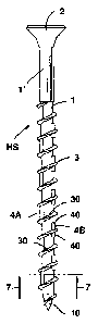
The illustrations figure 1 to 6 show some preferred embodiments of inventive
screws. The
screws are each embodied as wood screws HS and each include a screw shank l',
a screw
head 2, at least one thread section 3 having a thread core 1 as well as
multiple elevations 4 or
4', respectively, 4A and/or 4B.
The screw shank l' has an essentially cylindrical shank body having a
longitudinal axis 11.
On one end of the screw shank 1' there is formed a conical tip 10, and on the
other opposite
end of the screw shank l' there is formed a screw head 2. The thread section 3
extends from
the conical tip 10 along the direction towards the opposite other end of the
screw shank l',
on which the screw head 2 is arranged, so that multiple successive thread
turns 30 are
formed on a shell surface of the thread core I.
On the front side of the screw head 2 there is formed, as is shown in figure
2, a driving
profile 20. This driving profile 20 may have any profile known from prior art
per se and may
include, for example, a straight slit, a cross slit, a polygonal recess or a
star-like recess, in
order to being able to receive an appropriate tool such as, e.g., a
screwdriver etc. having a
connection form or support form, respectively, that is complementary to the
driving profile
20. As shown in the two illustrations figure 1 and 2, the screw head 2 may
have any of
various forms such as, e.g. a round or polygonal, respectively, form. Figure 1
shows a wood
screws HS having a screw head 2, e.g., having an internal hexagon socket, and
figure 2
shows, for example, a wood screw HS having a combined screw head 2, wherein
herein
there is embodied an internal Torx as well as an external hexagon socket as
two different
driving profiles 20. In this way, there may be produced a connection with a
corresponding
manual or electric tool by way of the screw head 2 itself or the driving
profile 20,
respectively, in order to enable turning or screwing-in, respectively, of the
wood screws (HS)
shown.
The elevations 4 or 4A, respectively, shown in the illustrations figure 1 to 6
are formed to
the shell surface of the thread core 1, and they each connect the edges of the
thread turns 30.
As shown in the sectional view according to figure 7, which shows the wood
screw HS
shown in figure 6 in a schematic sectional view in the longitudinal axis
direction 11
according to the sectional line 7-7 indicated in figure 6, a radial thickness
42 of the
CA 02913324 2015-11-24
14
elevations 4 or 4A, respectively, herein preferably amounts to about 2/3 of a
radial height 32
of the thread turns 30. The elevations 4 or 4A, respectively, are herein
oriented essentially in
parallel to the longitudinal axis direction 11 of the wood screw HS, wherein
the external
surfaces of the elevations 4 or 4A, respectively, form a curvilinear area or
have a curvilinear
outline, respectively. As can be further seen in figure 7, a radius 12 of the
thread core 1 is
smaller than a radius 12' of the screw shank l', which herein in figure 7 is
indicated in
dashed lines. The radial thickness 42 of the elevations 4 or 4A, respectively,
is thus larger
than the radius 12' of the screw shank 1'. In this way there is prevented,
while screwing in a
screw having a partial thread into a component, that - due the shank diameter
of the screw
shank l' being increased in comparison to the core diameter of the thread core
1 - the
friction of the wood screw HS will be disadvantageously increased.
According to the preferred embodiment examples according to the illustrations
figure 1 to 4
the elevations 4 on the shell surface of the thread core 1 are formed in at
least one straight
line as well as in the longitudinal axis direction 11 spaced apart from each
other. The two
ends of each elevation 4 are each connected with an edge of two neighbouring
thread turns
30. The straight line consisting of the elevations 4 may be oriented in
parallel or at an angle
to the central axis of the screw shank 1.
In the two illustrations figure 1 and figure 2 the elevations 4 each are
arranged in a single
line or in a single peripheral section, respectively, on the shell surface of
the thread core 1.
In figure 3 the elevations 4 are arranged on the shell surface of the thread
core 1
diametrically opposing each other in two straight lines or in two peripheral
sections
diametrically opposing each other, respectively, each alternating and spaced
apart from each
other. Thereby, the elevations 4 are arranged in the two straight lines
respectively around a
thread flight or a thread turn 30, respectively, offset and alternating to
each other.
As an alternative it is further possible, as is shown in figure 4, that the
elevations 4 are
arranged diametrically on the shell surface of the thread core 1 in two
straight lines or in two
peripheral sections, respectively, diametrically opposite and spaced apart
from each other.
Thereby, the elevations 4 are arranged in the two straight lines diametrically
opposing each
other, each within the same thread flight or the same thread turn 30,
respectively.
According to the preferred embodiment example shown in figure 5 of an
inventive wood
screw HS, herein elevations 4' are arranged on the shell surface of the thread
core 1 in at
least one straight line spaced apart from each other. Thereby, the elevations
4' are formed to
CA 02913324 2015-11-24
the thread turns 30 of the thread section 3, spaced apart from each other in
the longitudinal
axis direction 11. Accordingly, the elevations 4' form a projection 40 on both
sides of the
thread turns 30. The elevations 4' are arranged ¨ as shown in figure 5 ¨ on
the thread core 1
in parallel to the longitudinal axis 11 of the screw HS. Similarly, the
elevations 4 or 4',
respectively, may be oriented on the thread core 1 also at an angle or at
multiple and
different angles to the central axis 11.
According to the preferred embodiment example shown in the illustrations
figure 6 and
figure 7 of a wood screw HS, there may be arranged also multiple projections
4A, 4B in
different peripheral sections on the shell surface of the thread core 1.
Therefore, the
elevations are herein separated into first elevations 4A and second elevations
4B. The first
elevations 4A are formed on the shell surface of the thread core 1 in a
straight line in the
longitudinal direction II spaced apart from each other. The two ends of each
of the first
elevations 4A are connected with respectively one edge of two neighbouring
thread turns 30.
The second elevations 4B are formed on the shell surface of the thread core 1
in another
straight line also in the longitudinal axis direction 11, spaced apart from
each other. Each of
the second elevations 4B is formed to one of the thread turns 30 of the thread
section 3, and
it correspondingly forms respectively one projection 40 on both sides of the
thread turns 30.
The straight lines of the elevations 4A or 4B, respectively, may be oriented ¨
as shown in
figure 6 ¨ on the thread core 1 in parallel to the central axis or the
longitudinal axis 11,
respectively, of the screw. Similarly, it is further possible within the scope
of the invention
that the elevations 4A and/or the elevations 4B are arranged at an angle or,
however, at
various angles in regard to the longitudinal axis direction 11 on the shell
surface of the
thread core 1.
Figure 8 show a further preferred embodiment example of an inventive wood
screw HS,
wherein herein, in the region of the conical tip 10 and of the thread section
3 situated at the
conical tip 10, a groove 5 is cut out or milled into, respectively. The groove
5 forms a blade
and a chip space for facilitating screwing-in of the wood screw HS into a
component not
depicted herein.
The previously mentioned developments of the inventive wood screw HS enable
that, as
shown in the figures 9 and 10, when the wood screw HS is screwed into a
component 6 such
as a wood component, thus being inserted into this component 6, the interior
of the material
of the component 6 will be pressed by the thread section 3 or the thread core
1, respectively,
and also by the elevations 4 projecting beyond the shell surface of the thread
core 1. In this
way, there is realized an especially advantageous securing function against
screwing-out of
CA 02913324 2015-11-24
16
the screw, after the screw has been screwed into the component 6. Due to the
securing
function of the elevations 4, namely the first elevations 4A and the second
elevations 4B, on
the shell surface of the thread core 1, the wood screw HS in the component 6
has an
especially high retraction carrying capacity and will not become loose easily
by itself by way
of application of external forces onto the component 6.
As shown in figure 11, herein an inventive wood screw HS has, apart from the
thread section
3 having a thread core 1, also a further thread section 3A, which is arranged
spaced apart
from the thread section 3 on the screw shank. Elevations 4 may also be
arranged between the
thread turns 30 of the thread section 3A on the shell surface of the thread
core 1.
Further, it is possible within the scope of the invention to provide a wood
screw that is not
explicitly depicted herein, which in addition to a first thread section 3,
which includes
multiple elevations 4, includes at least one further thread section 3A, in
which further thread
section there are not provided elevations 4 between the thread turns 30.
The illustrations figure 12 and figure 13 each show inventive wood screws HS,
wherein the
embodiment shown in figure 12 includes a complete thread having a thread
section 3 with
thread turns 30 along a thread section length 31, which thread section 3
extends from the
conical tip 10 to the screw head 2. The thread core 1 of the continuous thread
section 3 is
herein the screw shank of the screw having a complete thread.
In contrast thereto, in figure 13 there is depicted a wood screw HS, which is
different from
the embodiment shown in figure 12 essentially by a partial thread, this is a
thread section 3
having a reduced thread section length 31. The thread section length 31 herein
extends from
the conical tip 10 in the longitudinal axis direction 11 to about 80% of the
length of the
screw body, wherein a smooth section of the screw shank l' up to the screw
head 2 will
remain without a thread. In both embodiments of the inventive wood screw HS
according to
figure 12 as well as according to figure 13, the elevations 4A as well as 4B
are each arranged
in parallel to the longitudinal axis direction 11 on the external surface of
the shell surface of
the thread core 1 in the region of the thread section 3 or along the
respective thread section
length 31, respectively.
For this purpose, the elevations 4A, 4B are arranged in at least two
peripheral sections of the
thread core 1 in the peripheral direction alternating and offset to each
other, wherein the first
elevations 4A are arranged in a first peripheral section as well as the second
elevations 4B in
the longitudinal axis direction II, each alternating to the first elevations
4A in a second
CA 02913324 2015-11-24
17
peripheral section. The two peripheral sections are diametrically opposite on
the shell
surface of the thread core 1. The first elevations 4A in the first peripheral
section each are
connected with an edge of two neighbouring thread turns 30, and the second
elevations 4B in
the second peripheral section are each formed to the thread turns 30 of the
thread section 3,
wherein the second elevations 4B each form projections 40 on both sides of the
thread turns
30.
As can further be seen in the illustrations figure 12 or figure 13,
respectively, in the wood
screws HS shown herein there is arranged respectively only one elevation 4A or
4B on the
shell surface of the thread core 1 in the longitudinal axis direction 11 per
longitudinal axis
section 11' or 11", respectively. The external surfaces of the elevations 4A,
4B each have a
curvilinear area or a curvilinear outline, respectively. The radial thickness
42 of the
elevations 4A, 4B herein preferably amounts to 2/3 or about 66%, respectively,
of the radial
height 32 of the thread turns 30.
Similarly, in the inventive embodiment of a wood screw HS having a complete
thread shown
in figure 14 there is arranged in the longitudinal axis direction 11 per
longitudinal axis
section respectively only one elevation 4 on the shell surface of the thread
core 1. In this
embodiment the elevations 4 are arranged each in parallel to the longitudinal
axis direction
11 in a straight line on the shell surface of the thread core 1. The
elevations 4 each connect
the edges of two neighbouring thread turns 30 or thread pitches 30,
respectively.
As an alternative to the embodiments shown in figure 12 or figure 13,
respectively, it is also
possible within the scope of the invention to provide wood screws, in which
directly
neighbouring elevations 4 or 4A, respectively, are arranged in the
longitudinal axis direction
11 in peripheral sections, which peripheral sections are offset to each other,
for example, by
a quarter turn, on the shell surface of the thread core 1. This embodiment is,
for example,
illustrated in figure 15 by way of a wood screw HS having a partial thread.
CA 02913324 2015-11-24
18
List of reference numbers.
HS wood screw
1 thread core
l' screw shank
conical tip
11 longitudinal axis of the screw
11' longitudinal axis section (or 11", respectively)
12 radius of the thread core
12' radius of the screw shank
2 screw head
driving profile
3 thread section
3A thread section
thread turn or thread pitch, respectively
31 length of the thread section
32 radius or radial height, respectively, of the thread turn
4 elevation
4' elevation
4A first elevation
4B second elevation
projection
42 radius or radial thickness, respectively, of the elevation
5 groove
6 component