Language selection

Search

Patent 2913531 Summary

Third-party information liability

Some of the information on this Web page has been provided by external sources. The Government of Canada is not responsible for the accuracy, reliability or currency of the information supplied by external sources. Users wishing to rely upon this information should consult directly with the source of the information. Content provided by external sources is not subject to official languages, privacy and accessibility requirements.

Claims and Abstract availability

Any discrepancies in the text and image of the Claims and Abstract are due to differing posting times. Text of the Claims and Abstract are posted:

  • At the time the application is open to public inspection;
  • At the time of issue of the patent (grant).
(12) Patent: (11) CA 2913531
(54) English Title: ION MOBILITY SPECTROMETERS
(54) French Title: SPECTROMETRES DE MOBILITE IONIQUE
Status: Granted and Issued
Bibliographic Data
(51) International Patent Classification (IPC):
(72) Inventors :
  • ATKINSON, JONATHAN RICHARD (United Kingdom)
(73) Owners :
  • SMITHS DETECTION-WATFORD LIMITED
(71) Applicants :
  • SMITHS DETECTION-WATFORD LIMITED (United Kingdom)
(74) Agent:
(74) Associate agent:
(45) Issued: 2019-12-03
(22) Filed Date: 2008-03-06
(41) Open to Public Inspection: 2008-09-18
Examination requested: 2015-11-27
Availability of licence: N/A
Dedicated to the Public: N/A
(25) Language of filing: English

Patent Cooperation Treaty (PCT): No

(30) Application Priority Data:
Application No. Country/Territory Date
0704547.9 (United Kingdom) 2007-03-09

Abstracts

English Abstract

An ion mobility spectrometer has a reaction region separated from a drift region by an electroststic gate. A doping circuit supplies a dopant to the reaction region but the drift region is undoped. Two high field ion modifiers are located one after the other in the drift region. One modifier can be turned on to remove dopant adducts from the admitted ions or both can be turned on so that the ions are also fragmented. In this way, several different responses can be produced to provide additional information about the nature of the analyte substance and distinguish from interferents.


French Abstract

Un spectromètre de mobilité ionique a une région de réaction séparée dune région de dérive par un portillon électrostatique. Un circuit de dopage fournit un dopant à la région de réaction, mais la région de dérive reste non dopée. Deux modificateurs dions de haute intensité sont positionnés lun derrière lautre dans la région de dérive. Un modificateur peut être activé pour retirer les adduits de dopant des ions admis ou les deux modificateurs peuvent être activés de façon à fragmenter les ions. Plusieurs réponses différentes peuvent ainsi être produites afin de fournir des renseignements supplémentaires sur la nature de la substance à analyser et de la distinguer des éléments interférents.

Claims

Note: Claims are shown in the official language in which they were submitted.

6
CLAIMS:
1. An ion mobility spectrometer comprising:
an ionisation source;
a drift region;
a reaction region in which ions produced by the ionisation source react with
analyte molecules, wherein the spectrometer is configured to dope the reaction
region
without doping the drift region; and
an ion modifier element located along an ion flow path so the ion modifier
element is effective when operated to undope and/or modify ions.
2. The ion mobility spectrometer as defined in claim 1, wherein the ion
modifier
element is configured to remove a dopant adduct from an ion.
3. The ion mobility spectrometer as defined in claim 1, wherein the ion
modifier
element is configured to establish an electrical field that is sufficiently
high to fragment
the ions.
4. The ion mobility spectrometer as defined in claim 1, wherein the ion
modifier
clement comprises: at least two selectively operable ion modifiers located one
after the
other along the ion flow path.
5. The ion mobility spectrometer as defined in claim 4, wherein at least
one of the
ion modifiers is effective to raise at least some of an ion's temperature
sufficiently high to
cause said ions to fragment.
6. The ion mobility spectrometer as defined in claim 1, wherein the ion
mobility
spectrometer is additionally configured to flow filtered gas through the drift
region to
remove dopant.

7
7. The ion mobility spectrometer as defined in claim 1, additionally
comprising:
a doping circuit arranged to supply a dopant at an end of the reaction region
adjacent the drift region and to remove dopant vapor at an opposite end of the
reaction
region so the dopant flows away from the drift region.
8. The ion mobility spectrometer as defined in claim 1, additionally
comprising:
an electrostatic gate between the reaction region and the drift region.
9. The ion mobility spectrometer as defined in claim 1, wherein the ion
mobility
spectrometer is configured to operate the ion modifier element in response to
detection of
a peak corresponding to a known interferent to remove dopant adducts.
10. The ion mobility spectrometer as defined in claim 1, wherein the ion
mobility
spectrometer is configured to derive a first output when the ion modifier
element is
operated in a first mode, a second output when the ion modifier element is
operated in a
second mode, and a third output when the ion modifier element is operated in a
third
mode.
11. The ion mobility spectrometer as defined in claim 1, additionally
comprising:
an arrangement to establish a voltage gradient in the reaction region to draw
ions
towards the drift region.
12. The ion mobility spectrometer as defined in claim 1, additionally
comprising:
an arrangement to establish a voltage gradient in the drift region to draw
ions from
adjacent the reaction region to a drift region's end opposite the reaction
region.
13. The ion mobility spectrometer as defined in claim 1, additionally
comprising:
a detection apparatus located near a second end of a drift chamber and
providing
an output indicative of ions detected by said detection apparatus.

8
14. An ion mobility spectrometer comprising:
an ionisation source;
a drift region;
a reaction region in which ions produced by the ionisation source react with
analyte molecules, wherein the spectrometer is configured to dope the reaction
region
without doping the drift region; and
an ion modifier element, located along an ion flow path, selectably operable
in
two different modes, wherein subsequent to operation in a first mode that
causes the ion
mobility spectrometer to produce a first result the ion modifier element is
configured to
operate in at least another mode to produce at least one other result.
15. The ion mobility spectrometer as defined in claim 14, wherein the ion
modifier
element is selectively operable in three modes, that result in the ion
mobility spectrometer
providing a different output.
16. The ion mobility spectrometer as defined in claim 14, wherein the ion
modifier
element comprises:
two or more selectively operable ion modifiers located one after the other
along
the ion flow path.
17. The ion mobility spectrometer as defined in claim 16, wherein one of
the ion
modifiers is arranged to remove dopant adducts from ions.
18. The ion mobility spectrometer as defined in claim 16, wherein one of
the ion
modifiers is arranged to modify ions.
19. The ion mobility spectrometer as defined in claim 14, wherein the ion
mobility
spectrometer is additionally configured to flow filtered gas through the drift
region to
remove dopant.

9
20. The ion mobility spectrometer as defined in claim 14, additionally
comprising:
a doping circuit arranged to supply a dopant to the reaction region adjacent
the
drift region so the dopant flows away from the drift region and to remove the
dopant at an
opposite end of the reaction region.
21. The ion mobility spectrometer as defined in claim 14, additionally
comprising:
an electrostatic gate between the reaction region and the drift region.
22. A method comprising:
doping a reaction region of an ion mobility spectrometer without doping a
drift
region of the ion mobility spectrometer, wherein the reaction region comprises
a region in
which ions produced by an ionisation source react with analyte molecules; and
selectively operating an ion modifier element located along an ion flow path
so the
ion modifier element is effective when operated to undope and/or chemically
modify ions.

Description

Note: Descriptions are shown in the official language in which they were submitted.


CA 02913531 2015-11-27
1
ION MOBILITY SPECTROMETERS
The present application is a divisional application of Canadian Patent
Application
No. 2,680,077 filed on March 6, 2008.
This invention related to ion mobility spectrometers of the kind having a
drift region
and a reaction region.
Ion mobility analysis is a commonly used technique for detecting the presence
of
explosives, hazardous chemicals and other vapours. An ion mobility
spectrometer (IMS)
typically includes a detector cell to which a sample of air containing a
suspected substance
or analyte is continuously supplied as a gas or vapour. The cell operates at
or near
atmospheric pressure and contains electrodes energized to produce a voltage
gradient along
the cell. Molecules in the sample of air are ionized, such as by means of a
radioactive
source, UV source or by corona discharge, and are admitted into the drift
region of the cell
by an electrostatic gate at one end. The ionized molecules drift to the
opposite end of the cell
at a speed dependent on the mobility of the ion. By measuring the time of
flight along the
cell it is possible to identify the ion.
In an undoped IMS system, it has been found that certain nerve agents produce
identifiable breakdown peaks when subject to ion modification by a high
electrical field.
This leads to an increase in the information that can be gained from the
spectrum and leads
to a greater confidence in analyte detection.
It is common practice to improve detection by adding a dopant substance to the
analyte substance in order to distinguish between an interferent substance
producing a
similar spectral output. The dopant is selected to combine with the substance
of interest so
that an identifiable pair of spectral peaks are produced in respect of the
undoped and doped
analyte substance. The dopant is also selected so that it does not combine
with the
interferent substance, or combines in a manner that produces a readily
distinguishable output
different from the substance of interest.

CA 02913531 2015-11-27
2
It has been found that ion modification is not possible in a doped system.
Instead, the
ion modification process removes the dopant adducts from certain ions without
producing
any modification of the ion itself This may be because the dopant adduct is
only removed
from the ion when it has passed most of the way through the modifier and there
is
insufficient distance left in the modifier for further ion modification to
take place.
De-adducted ions will only remain this way if the region of the ion modifier
is free of dopant
since, otherwise, recombination will occur.
It is an object of the present invention to provide an alternative ion
mobility
spectrometer.
According to one aspect of the present invention there is provided an ion
mobility
spectrometer of the above-specified kind, characterised in that the
spectrometer is arranged
to dope the reaction region without doping the drift region, that the
spectrometer includes at
least two selectively operable ion modifiers located one after the other along
the ion flow
path such that at least one modifier is effective when operated to remove
dopant adducts
from the ions.
At least one of the ion modifiers is preferably arranged to establish a high
electrical
field sufficient to fragment the ions. Alternatively, at least one of the ion
modifiers may be
effective to raise the temperature to a level sufficient to fragment the ions.
The spectrometer
preferably includes a filtered gas flow path flowing through the drift region
to remove any
dopant from the drift region. The spectrometer may include a doping circuit
arranged to
supply a dopant vapour to a region of the reaction region adjacent the drift
region and to
remove the dopant vapour at the opposite end of the reaction region such that
the dopant
flows away from the drift region. The spectrometer may include an
electrostatic gate
between the reaction region and the drift region. The spectrometer may be
arranged to
operate the ion modifiers in response to detection of a peak corresponding to
a known
interferent such that dopant adducts are then removed. The spectrometer may be
arranged to
derive a first output when both ion modifiers are off, a second output when
one ion modifier
only is on and a third output when both ion modifiers are on.

CA 02913531 2015-11-27
3
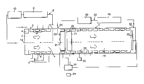
An ion mobility spectrometer according to the present invention will now be
described, by way of example, with reference to the accompanying drawing,
which is a
schematic diagram of the spectrometer.
The spectrometer has a tubular drift cell 1 with an inlet 2 at its left-hand
end by
which a sample analyte gas or vapour enters the cell via a selective barrier
such as a
membrane, pinhole or the like (not shown). The inlet 2 opens into an
ionisation region 3
including some conventional ionisation source 4, such as a corona ionisation
point, a
radioactive source, UV photoionisation source or the like. The ionisation
region 3 opens into
a reaction region 5 in which ions produced by the source 4 react with the
analyte molecules.
The reaction region 5 includes several electrode pairs 6 spaced along the
region and driven
by a voltage source 7 to produce a potential gradient along the region that
draws ions to the
right. The reaction region 5 is connected into a doping circuit 8 including a
conventional
dopant source 9 and a pump 10. The outlet 11 of the circuit 8 is connected to
the cell 1 at the
right-hand end of the reaction region 5; its inlet 12 is connected to the left-
hand end of the
reaction region so that dopant gas flows along the reaction region from right
to left.
The right-hand end of the reaction region 5 communicates with a drift region
20 via a
conventional electrostatic gate 21 by which ions from the reaction region 5
are admitted into
or excluded from the drift region. Operation of the gate 21 is controlled by a
processing and
control unit 22. The drift region 20 includes an ion collector or detector
plate 23, the output
of which is connected with an input of the processing unit 22 so as to produce
an output
spectrum representative of the ions incident on the plate, in the usual way.
The output is
supplied to a display 24 or other utilisation means. Electrode pairs 25 spaced
along the drift
region 20 are connected with a voltage source 26 to provide a potential
gradient along the
length of the drift region effective to draw the ions from left to right
towards the collector
plate 23.
Immediately adjacent the gate 21 inside the drift region 20 are mounted two
ion
modifiers 30 and 31, each in the form of a pair of parallel electrode grids
extending laterally
of the ion flow path, which is axially along the cell 1. The construction of
the grids 30 and

CA 02913531 2015-11-27
4
31 is such as to allow ions to pass freely through them and, in this respect,
the grids are
preferably made from a mesh of electrically-conductive wires with spaces
between them
through which the ions can flow. The ion modifiers 30 and 31 are connected to
the
processing unit 22, which is operable to apply a high voltage between the
grids sufficient to
modify the nature of any ions in the space between the grids, such as by
fragmentation of the
ions. An additional effect of this high field is to remove the dopant adducts
from the ions.
Alternative ion modifiers may be possible such as involving heating,
radiation, electrical
discharge, magnetic fields or lasers. Although the ion modifiers 30 and 31 are
shown as
being close to one another they could be spaced from one another, with the
downstream,
right-hand modifier being located a distance along the drift region 20.
Clean dry air is circulated along the drift region 20 by an air flow system 32
having
an outlet 33 into the cell 1 adjacent the collector plate 23. The inlet 34 of
the system 32 is
located just to the left of the gate 21. The air flow system 32 includes a
pump 35 and a filter
in the form of a molecular sieve 36 connected in series between the inlet 34
and the outlet
33. Air is, therefore, circulated to flow from right to left along the drift
region 20 and is
dried and cleaned by the action of the molecular sieve 36. The air flow system
32 is
effective to remove any dopant vapour that might permeate into it from the
reaction region
5. In this way, the reaction region 5 is doped and the drift region 20 is
undoped.
In operation, analyte sample vapour is admitted to the cell assembly I via the
inlet 2
and is doped and ionized in the reaction chamber 5. The resultant ions are
then moved by the
field established by the plates 6 towards the gate 21. The doped ions are
admitted in a timed
fashion by the gate 21 under control of the processing/control unit 22 and
enter the drift
region 20. In normal operation, with the ion modifiers 30 and 31 unenergised
and
inoperative, the doped ions move along the drift region 20 to the detector
plate 23 and
produce corresponding responses at the processor 22. If, however, the output
includes a peak
for which there is a known interferent, both ion modifiers 30 and 31 are
turned on to render
them operative. The effect of this is that the upstream, left-hand modifier 30
removes any
dopant adduct from the ions passing through it. The, now undoped, ions pass to
the

CA 02913531 2015-11-27
downstream modifier 31 where they are further modified to cause fragmentation
or other
changes in the ion chemistry of the ions. Because the drift region 20 is
undoped, the
undoped and modified ions move along the region without being exposed to any
dopant.
This causes a change in the output response at the collector plate 23 so that
the response
produced by the analyte substance of interest and its interferent will
generally be different
when the ion modifiers 30 and 31 are turned on. By characterising the
apparatus before use
with the analyte substance and its interferent, it is, therefore, possible to
distinguish between
the substance and its interferent.
The system could be arranged such that the output of the collector plate 23
was
monitored initially with only one modifier 30 operative so that the only
change was the
removal of the dopant adducts. Then the second modifier 31 could be turned on.
In this way,
three different outputs would be produced: one derived from doped ions, with
neither
modifier on; a second derived from undoped, unmodified ions, with one modifier
on; and
the third derived from undoped, modified ions, with both ion modifiers on.
It will be appreciated that the spectrometer could have more than two ion
modifiers.

Representative Drawing
A single figure which represents the drawing illustrating the invention.
Administrative Status

2024-08-01:As part of the Next Generation Patents (NGP) transition, the Canadian Patents Database (CPD) now contains a more detailed Event History, which replicates the Event Log of our new back-office solution.

Please note that "Inactive:" events refers to events no longer in use in our new back-office solution.

For a clearer understanding of the status of the application/patent presented on this page, the site Disclaimer , as well as the definitions for Patent , Event History , Maintenance Fee  and Payment History  should be consulted.

Event History

Description Date
Revocation of Agent Requirements Determined Compliant 2022-05-04
Revocation of Agent Request 2022-05-04
Change of Address or Method of Correspondence Request Received 2022-05-04
Common Representative Appointed 2020-11-07
Grant by Issuance 2019-12-03
Inactive: Cover page published 2019-12-02
Common Representative Appointed 2019-10-30
Pre-grant 2019-10-21
Inactive: Final fee received 2019-10-21
Notice of Allowance is Issued 2019-04-30
Letter Sent 2019-04-30
4 2019-04-30
Notice of Allowance is Issued 2019-04-30
Inactive: Approved for allowance (AFA) 2019-04-25
Inactive: Q2 passed 2019-04-25
Amendment Received - Voluntary Amendment 2018-11-08
Inactive: S.30(2) Rules - Examiner requisition 2018-05-11
Inactive: Report - No QC 2018-05-10
Amendment Received - Voluntary Amendment 2017-11-08
Inactive: S.30(2) Rules - Examiner requisition 2017-05-11
Inactive: Report - No QC 2017-05-11
Amendment Received - Voluntary Amendment 2016-11-28
Inactive: S.30(2) Rules - Examiner requisition 2016-05-30
Inactive: Report - No QC 2016-05-30
Inactive: Cover page published 2016-01-13
Inactive: IPC assigned 2015-12-14
Inactive: First IPC assigned 2015-12-14
Divisional Requirements Determined Compliant 2015-12-08
Correct Applicant Requirements Determined Compliant 2015-12-03
Letter sent 2015-12-03
Letter Sent 2015-12-03
Correct Applicant Requirements Determined Compliant 2015-12-03
Application Received - Regular National 2015-12-02
Application Received - Divisional 2015-11-27
Request for Examination Requirements Determined Compliant 2015-11-27
All Requirements for Examination Determined Compliant 2015-11-27
Application Published (Open to Public Inspection) 2008-09-18

Abandonment History

There is no abandonment history.

Maintenance Fee

The last payment was received on 2019-02-06

Note : If the full payment has not been received on or before the date indicated, a further fee may be required which may be one of the following

  • the reinstatement fee;
  • the late payment fee; or
  • additional fee to reverse deemed expiry.

Patent fees are adjusted on the 1st of January every year. The amounts above are the current amounts if received by December 31 of the current year.
Please refer to the CIPO Patent Fees web page to see all current fee amounts.

Owners on Record

Note: Records showing the ownership history in alphabetical order.

Current Owners on Record
SMITHS DETECTION-WATFORD LIMITED
Past Owners on Record
JONATHAN RICHARD ATKINSON
Past Owners that do not appear in the "Owners on Record" listing will appear in other documentation within the application.
Documents

To view selected files, please enter reCAPTCHA code :


To view images, click a link in the Document Description column (Temporarily unavailable). To download the documents, select one or more checkboxes in the first column and then click the "Download Selected in PDF format (Zip Archive)" or the "Download Selected as Single PDF" button.

List of published and non-published patent-specific documents on the CPD .

If you have any difficulty accessing content, you can call the Client Service Centre at 1-866-997-1936 or send them an e-mail at CIPO Client Service Centre.

({010=All Documents, 020=As Filed, 030=As Open to Public Inspection, 040=At Issuance, 050=Examination, 060=Incoming Correspondence, 070=Miscellaneous, 080=Outgoing Correspondence, 090=Payment})


Document
Description 
Date
(yyyy-mm-dd) 
Number of pages   Size of Image (KB) 
Claims 2015-11-26 4 118
Description 2015-11-26 5 236
Abstract 2015-11-26 1 15
Drawings 2015-11-26 1 17
Representative drawing 2016-01-04 1 7
Representative drawing 2016-01-11 1 7
Claims 2016-11-27 4 121
Claims 2018-11-07 4 127
Representative drawing 2019-11-14 1 9
Acknowledgement of Request for Examination 2015-12-02 1 188
Commissioner's Notice - Application Found Allowable 2019-04-29 1 162
Amendment / response to report 2018-11-07 9 298
New application 2015-11-26 4 94
Courtesy - Filing Certificate for a divisional patent application 2015-12-02 1 146
Examiner Requisition 2016-05-29 4 248
Amendment / response to report 2016-11-27 10 324
Examiner Requisition 2017-05-10 4 185
Amendment / response to report 2017-11-07 2 115
Examiner Requisition 2018-05-10 6 279
Final fee 2019-10-20 2 43