Some of the information on this Web page has been provided by external sources. The Government of Canada is not responsible for the accuracy, reliability or currency of the information supplied by external sources. Users wishing to rely upon this information should consult directly with the source of the information. Content provided by external sources is not subject to official languages, privacy and accessibility requirements.
Any discrepancies in the text and image of the Claims and Abstract are due to differing posting times. Text of the Claims and Abstract are posted:
| (12) Patent: | (11) CA 2913600 |
|---|---|
| (54) English Title: | CONDUCTOR JOINT AND CONDUCTOR JOINT COMPONENT |
| (54) French Title: | JOINT CONDUCTEUR ET COMPOSANTE DE JOINT CONDUCTEUR |
| Status: | Granted and Issued |
| (51) International Patent Classification (IPC): |
|
|---|---|
| (72) Inventors : |
|
| (73) Owners : |
|
| (71) Applicants : |
|
| (74) Agent: | GOWLING WLG (CANADA) LLP |
| (74) Associate agent: | |
| (45) Issued: | 2019-01-08 |
| (22) Filed Date: | 2015-12-01 |
| (41) Open to Public Inspection: | 2016-06-04 |
| Examination requested: | 2017-11-29 |
| Availability of licence: | N/A |
| Dedicated to the Public: | N/A |
| (25) Language of filing: | English |
| Patent Cooperation Treaty (PCT): | No |
|---|
| (30) Application Priority Data: | ||||||
|---|---|---|---|---|---|---|
|
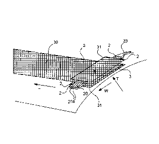
A conductor joint (1) for joining a copper conductor (2) to a fiber-structured heating element (3) whose dimensions are length (L) >> width (W) >> thickness (T), and which heating element (3) comprises carbon fiber strands (30), wherein the copper conductor (2) is transversely disposed to the longitudinal direction (L) of the heating element (3) to form a layered structure in the thickness direction (T), on both sides of the heating element (3), the copper conductor (2) comprising strands (20) separable from each other. The strands (20) of the copper conductor (2), the number and diameter of which are suitable for transferring a power of more than ten kW, are quantitatively substantially evenly distributed on both sides of the heating element (3), the strands (20) are disposed in a planar manner in such a way that the strands (20) substantially lie in one plane, adjacent to each other, and the ends (201) of the strands extend, in the width direction (W) of the heating element (3), beyond the heating element (3), wherein the portions of the ends (201) of the strands extending beyond the heating element (3) overlap each other, and an electric joint is formed between the lateral faces of these overlapping strands (20).
Un joint conducteur (1) pour relier un conducteur en cuivre (2) à un élément chauffant à structure de fibre (3) dont les dimensions sont longueur (L) >> largeur (W) >> épaisseur (T) et élément chauffant (3) comprend des brins de fibres de carbone (30), le conducteur en cuivre (2) étant disposé transversalement par rapport à la direction longitudinale (L) de lélément chauffant (3) pour former une structure en couches dans la direction de lépaisseur (T), des deux côtés de lélément chauffant (3), le conducteur en cuivre (2) comprenant des brins (20) séparables les uns des autres. Les brins (20) du conducteur en cuivre (2), dont le nombre et le diamètre permettent de transférer une puissance supérieure à dix kW, sont répartis quantitativement de manière sensiblement uniforme sur les deux côtés de lélément chauffant (3), les brins ( 20) sont disposés de manière plane de manière à ce que les brins (20) soient sensiblement dans un même plan, adjacents les uns aux autres, et les extrémités (201) des brins sétendent dans le sens de la largeur (W) du chauffage élément (3), au-delà de lélément chauffant (3), dans lequel les parties des extrémités (201) des brins sétendant au-delà de lélément chauffant (3) se chevauchent, et un joint électrique est formé entre les faces latérales de ces éléments se chevauchant des brins (20).
Note: Claims are shown in the official language in which they were submitted.
Note: Descriptions are shown in the official language in which they were submitted.
2024-08-01:As part of the Next Generation Patents (NGP) transition, the Canadian Patents Database (CPD) now contains a more detailed Event History, which replicates the Event Log of our new back-office solution.
Please note that "Inactive:" events refers to events no longer in use in our new back-office solution.
For a clearer understanding of the status of the application/patent presented on this page, the site Disclaimer , as well as the definitions for Patent , Event History , Maintenance Fee and Payment History should be consulted.
| Description | Date |
|---|---|
| Common Representative Appointed | 2019-10-30 |
| Common Representative Appointed | 2019-10-30 |
| Grant by Issuance | 2019-01-08 |
| Inactive: Cover page published | 2019-01-07 |
| Pre-grant | 2018-11-21 |
| Inactive: Final fee received | 2018-11-21 |
| Letter Sent | 2018-07-17 |
| Notice of Allowance is Issued | 2018-07-17 |
| Notice of Allowance is Issued | 2018-07-17 |
| Inactive: Q2 passed | 2018-07-13 |
| Inactive: Approved for allowance (AFA) | 2018-07-13 |
| Amendment Received - Voluntary Amendment | 2018-06-06 |
| Change of Address or Method of Correspondence Request Received | 2018-01-10 |
| Inactive: S.30(2) Rules - Examiner requisition | 2017-12-13 |
| Inactive: Report - QC passed | 2017-12-12 |
| Letter Sent | 2017-12-06 |
| Request for Examination Requirements Determined Compliant | 2017-11-29 |
| Advanced Examination Requested - PPH | 2017-11-29 |
| Advanced Examination Determined Compliant - PPH | 2017-11-29 |
| Amendment Received - Voluntary Amendment | 2017-11-29 |
| Request for Examination Received | 2017-11-29 |
| All Requirements for Examination Determined Compliant | 2017-11-29 |
| Amendment Received - Voluntary Amendment | 2016-08-04 |
| Inactive: Cover page published | 2016-06-08 |
| Application Published (Open to Public Inspection) | 2016-06-04 |
| Inactive: First IPC assigned | 2015-12-18 |
| Inactive: IPC assigned | 2015-12-18 |
| Inactive: IPC assigned | 2015-12-18 |
| Inactive: IPC assigned | 2015-12-10 |
| Application Received - Regular National | 2015-12-03 |
| Filing Requirements Determined Compliant | 2015-12-03 |
| Inactive: Filing certificate - No RFE (bilingual) | 2015-12-03 |
| Inactive: Applicant deleted | 2015-12-03 |
| Small Entity Declaration Determined Compliant | 2015-12-01 |
There is no abandonment history.
The last payment was received on 2018-11-13
Note : If the full payment has not been received on or before the date indicated, a further fee may be required which may be one of the following
Please refer to the CIPO Patent Fees web page to see all current fee amounts.
| Fee Type | Anniversary Year | Due Date | Paid Date |
|---|---|---|---|
| Application fee - small | 2015-12-01 | ||
| MF (application, 2nd anniv.) - small | 02 | 2017-12-01 | 2017-11-01 |
| Request for examination - small | 2017-11-29 | ||
| MF (application, 3rd anniv.) - small | 03 | 2018-12-03 | 2018-11-13 |
| Final fee - small | 2018-11-21 | ||
| MF (patent, 4th anniv.) - small | 2019-12-02 | 2019-11-18 | |
| MF (patent, 5th anniv.) - small | 2020-12-01 | 2020-11-20 | |
| MF (patent, 6th anniv.) - small | 2021-12-01 | 2021-11-25 | |
| MF (patent, 7th anniv.) - small | 2022-12-01 | 2022-11-15 | |
| MF (patent, 8th anniv.) - small | 2023-12-01 | 2023-11-22 |
Note: Records showing the ownership history in alphabetical order.
| Current Owners on Record |
|---|
| WICETEC OY |
| Past Owners on Record |
|---|
| PAULI VUOMAJOKI |
| TOMAS WALLENIUS |

