Note: Descriptions are shown in the official language in which they were submitted.
1
METHOD FOR INDICATING PROXIMITY, CORRESPONDING DEVICE, PROGRAM AND
RECORDING MEDIUM
1. Field of the invention
The invention pertains to the field of communications devices and more
particularly to
the detection of proximity or nearness between such communications devices, in
order to report
this proximity to a user of one of the two devices.
2. Prior art
There are known techniques for locating objects, based for example on
triangulation
calculations using several signals received from several transmitter
terminals. These techniques
are used for example to exchange data with a device located in a given area,
such as for example
a user's smartphone when he enters a store.
There also exist known techniques enabling several devices to communicate with
one
another provided that they are sufficiently close to one another. This is the
case for example with
TM
Bluetooth, RFID, NEC, and other technologies.
Thus, current techniques enable the contactless electronic payment (or
validation of
reduction coupons) or again contactless secured access to a building (or to
public transport). The
principle of these techniques relies on the presenting of a client apparatus
(for example an
electronic payment card, smartphone, an access badge or a public transport
card) to a "target"
apparatus such as an electronic payment terminal, an entry terminal for entry
to a building or to
public transport and on communications between the client equipment and the
target equipment
to carry out a transaction or authorize access.
One major drawback of these techniques lies in the difficulty for a visually
impaired user
to position his client apparatus close enough to the target apparatus for a
communications link to
be initiated without being guided by external help. Indeed, in certain
situations of use, external
help is not recommended for security reasons, such as for example for
contactless electronic
payment.
Date Recue/Date Received 2022-04-21
CA 02913708 2015-12-01
2
3. Summary of the invention
The invention proposes a novel solution which does not have all these
drawbacks of the
prior art in the form of a method for indicating proximity implemented in a
proximity indicating
module attached to a first communications device, called a detector device,
between the detector
device and a second communications device called a device to be detected, the
detector device
corresponding to an electronic card case and the method comprising at least
one iteration of the
following steps:
= receiving at least one signal sent out by the device to be detected;
= determining, from the received signal, at least one indication of
proximity between
the device to be detected and the detector device;
= generating at least one sound signal and/or vibratory signal representing
the
determined indication of proximity;
= sending the generated sound and/or vibratory signal.
Thus, the invention proposes a novel and inventive solution to the indication
of proximity
between two devices, based firstly on determining an indication of proximity
between the two
devices on the basis of a signal received, by the detector device, coming from
the device to be
detected and secondly on generating a "sensory" signal (sound, vibration or
both) representing
this proximity.
Indeed, the method for indicating proximity according to the invention
implemented in a
proximity indication module attached to a detector device (for example
integrated into this device
or comprising this device) makes it possible not only to determine the
proximity between two
devices but also to send out a sensory signal depending on and representing
the proximity
determined. Thus, the sensory signal is not limited to a "binary" sensory
signal activated through
a certain piece of proximity information but varies according to the
determined value of
proximity. For example, the intensity, frequency or again the very shape of
the sensory signal
generated varies as a function of the degree of proximity between the two
devices.
In addition, the "sensory" signal generated and sent by the proximity
indicating module
according to the method of the invention is designed to be picked up or sensed
by a visually
impaired user and is therefore distinguished from a visual signal. For
example, when a visually
CA 02913708 2015-12-01
3
impaired user seeks to bring a detector device, provided with a proximity
indicating module
implementing the method according to the invention, closer to a device to be
detected, without
seeing this device to be detected, the proximity indication module vibrates
(at varying degrees of
intensity depending on proximity) or emits a sound (with varying degrees of
loudness or with
different sounds according to proximity) as and when the device to be detected
gets closer.
One particularly valuable application of the invention is that of assisted NFC
payment for a
visually impaired user. Thus, according to one embodiment of the invention,
the detector device
corresponds to a client apparatus, for example a smartphone or an electronic
card case or pouch
(for example an electronic payment card holder or an access card holder)
implementing the
method of the invention and furthermore comprising NEC type communications
means to carry
out NEC payments with an electronic payment terminal (constituting the device
to be detected). A
visually impaired user carrying a smartphone and wishing to make an NFC
payment with an
electronic payment terminal can therefore benefit from an indication of
proximity between his
smartphone and the electronic payment terminal via a sound and/or vibratory
signal sent out by
these smartphones depending on the distance from the electronic payment
terminal. For
example, his smartphone will vibrate with increasing intensity as he
approaches the electronic
payment terminal, thus enabling the visually impaired user to know that he is
pointing his
smartphone in the right direction.
In one variant of this embodiment, the card holder or card case for an
electronic payment
card is equipped with a proximity indication module according to the invention
so as to be made
"smart" and be able to help a visually impaired user as he brings his
electronic payment card
closer to the electronic payment terminal during an NFC payment.
The invention can also apply to the validation of reduction or loyalty coupons
on a same
principle as in an NEC payment.
In another application of the invention, a visually impaired user is helped to
obtain access
to a building or to public transport. This would be obtained by near-field
communication between
his smartphone or an access card carried in a smart case as described here
above and an entry
post of a building or an underground platform or tramway platform or again a
point of entry into
a bus.
CA 02913708 2015-12-01
4
Yet another application that can be envisaged, not dedicated to visually
impaired users,
relates to secured access to a room in a building, consisting solely of the
detection of the right
access card, this access besides being in no way visible so as to preserve its
security. Thus, a
building having several "clean rooms" dedicated to different operators or
groups of persons can
have secured access to each of these rooms only through the detection of the
authorized access
card at each room door, without any visual indication stating which operator
each room is
dedicated to.
For example, when the received signal corresponds to a radio signal, the step
for
determining an indication of proximity comprises a step for computing a
distance between the
devices, taking account of a measurement of a characteristic of the received
radio signal and at
least one piece of information on correspondence between a value of the
characteristic of the
signal and a distance.
Thus, this embodiment particularly enables the use of signals sent out by the
device to be
detected, not specifically dedicated to the present invention (for example
Bluetooth signals sent
out by a communication terminals for the purpose of pairing with another
communications
terminal) by measuring a characteristic of it in order to determine a distance
between the two
devices.
For example, the intensity or the power of a received signal coming from the
device to be
detected is measured and makes it possible, by application of a table of
correspondence between
a signal power and a distance, to determine an indication of the distance
between the two
devices. This table of correspondence indicates for example that, at a
distance of one meter
between the two devices, the level of the signal must correspond to a first
value whereas at a
distance of 50 cm, the level of the signal must correspond to a second value
and so on and so
forth. In this way, depending on the level of the signal measured, it is
possible to evaluate the
distance between the two devices.
An indication of proximity can therefore correspond to an evaluated distance
between
the two devices or to an interval comprising a minimum distance evaluated and
a maximum
distance evaluated between the two devices.
CA 02913708 2015-12-01
s
According to one particular aspect, the radio signal corresponds to a
Bluetooth low-
energy type signal and the measured characteristic corresponds to the level of
the signal received.
Thus, this embodiment enables the use of a Bluetooth Low Energy type radio
signal or
Bluetooth Smart signal emitted by the device to be detected and the
measurement of its level so
as to then determine the distance between the two devices.
Indeed, most electronic payment terminals already possess (or will possess)
this
Bluetooth Low Energy function and therefore send out signals of this type, the
power of which
can be measured to determine the proximity of the sender device relative to
the detector device.
Similarly, most snnartphone type mobile communications terminals also possess
this Blue
Tooth Low Energy function.
According to one particular characteristic, the step for generating the sound
signal and/or
vibratory signal comprises a step for parameterizing at least one
characteristic of the sound signal
and/or vibratory signal generated as a function of the determined indication
of proximity.
Thus, this embodiment makes it possible to vary a characteristic of the sound
and/or
vibratory signal sent out by the proximity indication module as a function of
the very value of the
determined indication of proximity.
For example, if it is a sound signal, its level can increase as the distance
between the two
devices diminishes or different sound patterns can be used depending on
distance (for example
from the lowest-pitched sounds to the highest-pitched sounds as the distance
diminishes).
If it is a vibratory signal, the level and/or frequency of the vibrations can
increase as the
distance between the two devices diminishes.
Finally, if it is a signal combining sound and vibrations, every combination
can be
considered (modification of sound only with constant vibrations, modification
of vibrations only
with constant sound signal, modification of both signals combined).
According to one particular embodiment, the number of iterations of the steps
for
receiving, determining, generating and sending depends on at least one
predetermined criterion
representing the indication of proximity determined at the previous iteration.
CA 02913708 2015-12-01
6
Thus, this embodiment limits the number of iterations of the different steps
of the
method according to the invention according to the indication of proximity
determined at the
previous iteration.
Finally, when the distance evaluated between the two devices is considered to
be
sufficient to carry out the desired application (for example so that the two
devices can
communicate according to predefined criteria), then the user must be made to
understand that
both devices are accurately positioned to implement the desired application.
For example, when the distance evaluated at the previous iteration is smaller
than a
certain predetermined threshold, then it is necessary either to continue
sending out the same
sound signal and/or vibratory signal or stop sending this signal so that the
user knows that he can
stop moving his device.
The invention also pertains to a proximity indicating module attached to a
first
communications device, called a detector device, between the detector device
and a second
communications device, called a device to be detected, the detector device
corresponding to an
electronic card case and the proximity indication module comprising the
following means:
= means for receiving at least one signal sent by the device to be
detected;
= means for determining, from the received signal, at least one indication
of proximity
between the device to be detected and the detector device;
= means for generating at least one sound signal and/or vibratory signal
representing
the determined indication of proximity;
= means for sending out the generated sound signal and/or vibratory signal.
For example, such a module is integrated into a communications terminal such
as a
smartphone or a tablet or else an electronic payment card case.
The invention also pertains to a computer program downloadable from a
communications
network and/or stored on a computer-readable medium and/or executable by a
microprocessor
for the implementation of a method as described here above, when this program
is executed by a
processor.
Finally, the invention pertains to a computer-readable recording medium on
which there
is recorded a computer program comprising a set of instructions executable by
a computer or a
CA 02913708 2015-12-01
7
processor to implement the method as described here above when this program is
executed by a
processor.
4. Figures
Other features and advantages of the invention shall appear more clearly from
the
following description of a preferred embodiment given by way of a simple,
illustratory and non-
exhaustive example and from the appended figures of which:
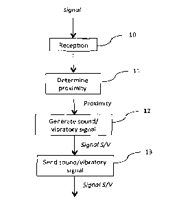
Figure 1 presents the main steps of the method for indicating proximity
according to one
particular embodiment of the invention;
Figure 2 presents a diagram of sequences according to one particular
embodiment of the
invention;
Figures 3a and 3b present two examples of a system that can implement the
method for
indicating proximity according to the invention, according to two particular
embodiments;
Figures 4 and 5 illustrate two examples of simplified architecture of a
proximity indicating
module according to one particular embodiment of the invention.
5. Description
5./. General principle
The general principle of the invention, described with reference to figures 1
and 2,
consists in determining an indication of proximity between two devices on the
basis of a signal
received by a first device, coming from a second device and sending a sound
signal and/or
vibratory signal representing this proximity to the user of the first device.
To this end, the invention is implemented in a specific module, here below
called a
proximity indication module, attached to the first device, i.e. for example
integrated into this first
device or carrying this first device.
Besides, since the sound and/or vibratory signal represents proximity, it
depends on the
indication of proximity, for example by varying certain of its own
characteristics.
For example, a visually impaired user seeking to bring a device in his
possession closer to
another remote device for a particular application requiring communications
between the two
devices, is informed of the distance remaining between his device and the
second device by a
sound signal and/or vibratory signal sent out by his own device.
CA 02913708 2015-12-01
8
As illustrated in figure 1, a first step 10 is therefore implemented within
the proximity
indication module for receiving a signal received from a remote device, hereby
denoted as a
device to be detected. This signal sent by the device to be detected is not
specific to the invention
but can be sent out in the context of any other application.
For example, such a signal corresponds to a Bluetooth Low Energy type signal
that can be
received at up to 50 meters. It is indeed increasingly frequent for a
communications terminal to
present such Bluetooth communications means, especially for locating
applications within. The
principle of this type of locating application or micro-locating application
relies on the layout of
several beacons sending out Bluetooth Low Energy signals capable of being
received by a
smartphone (or a tablet) equipped with an application to listen to these
beacons. When the
smartphone picks up the Bluetooth signals sent out by the beacon, it then
recognizes the beacon
from which the signal is coming and can estimate the distance at which this
beacon is situated in
analyzing the power of the signal for example.
This function can be used in the method of the invention, according to this
embodiment,
to determine the proximity between the first detector device (for example a
smartphone capable
of listening to a Bluetooth Low Energy signal) and the second device to be
detected (for example
an electronic payment terminal emitting Bluetooth Low Energy signals of this
kind).
Thus, from this signal received at the step 10, a step 11 to determine an
indication of
proximity is carried out in the proximity indicating module in order to
determine the distance or
the range of distances at which the two devices are situated from each other.
For example, the level of the received signal is enough to determine the
distance or an
order of magnitude of this distance between the two devices. In this case, the
step for
determining also uses a correspondence table to evaluate a distance on the
basis of a signal level.
To this end, a measurement of the strength of the received signal of the
"Received Signal Strength
Indication" (RSSI) type can be implemented.
According to another example, the received signal carries a piece of locating
information
for locating the device to be detected and the distance between the two
devices can be
computed by the proximity indicating module, the location of the detection
device being known.
This type of computation is well known and is not described in detail herein.
CA 02913708 2015-12-01
9
Once the indication of proximity has been determined at the step 11, a step 12
for
generating a sound and/or vibratory signal (denoted as Signal S/V here below)
representing the
indication of proximity is implemented. Thus, one or more characteristics of
the S/V signal are
parameterizable to "reflect" the degree of proximity determined for the
attention of the user
during the step 13 for sending this generated Signal S/V. This step for
generating an S/V signal is
described in greater detail here below with reference to different embodiments
of the invention.
Figure 2 for its part illustrates the progress of the steps described here
above as and when
the detector device moves towards the device to be detected.
Indeed, for the sound and/or vibratory signal S/V to be capable of reflecting
the degree of
proximity between the two devices, when one of the devices is mobile, then a
new indication of
proximity has to be determined in order to generate or emit a new sound signal
S/V representing
the current distance between the two devices.
To this end, the steps 10 to 13 described here above are reiterated, for
example
periodically, or upon reception of a new signal coming from the device to be
detected.
Thus, as illustrated in figure 2, a first signal Signal S/V1 is generated and
sent, following
the reception of a signal signal coming from the device to be detected and the
determination of
a first indication of proximity proximityl. Then, upon reception of a signal
signal2 coming from
the device to be detected, a second indication of proximity proximity2 is
determined so as to
generate and send out a second signal Signal S/V2.
Whatever the way in which the iterations are made (periodically or at
reception of a new
signal), the number of iterations of the steps of the method can be limited by
a minimum distance
beyond which it is no longer necessary to modify the sound signal and/or
vibratory signal sent out
or even to send it.
Indeed, it is considered that when the two devices are close enough to carry
out a desired
application (for example contactless payment), it is no longer necessary to
inform the user of the
degree of proximity. It can even be preferable to stop sending the sound
and/or vibratory signal
so that the user will know that he can stop moving his detector device and
leave it positioned at
the same place to carry out the desired application.
10
It must be noted that the invention according to its different embodiments is
based on
TM
the reception of signals sent out by a device capable of implementing any type
of radio, Wi-Fi or
non-standardized protocols, responding to the same set of problems and issues
for determining
proximity on the basis of a received signal.
5.2. Description of a first embodiment
Referring now to figures 3a and 3b, we shall now describe two variants of a
first particular
embodiment of the invention in which the detector device 30 corresponds to a
client's
smartphone and the device to be detected 31 corresponds to an electronic
payment terminal, the
two devices implementing NFC type near field communications means for carrying
out a
contactless payment application.
This type of contactless payment using NFC technology is being implemented
with
increasing frequency because it allows the user not to have to enter any
secret code to validate a
transaction, thus giving rise to considerable gain in time.
Besides, when this contactless payment technique implements a user's mobile
terminal
(for example a smartphone), it is based on a "card emulation" mode or
"passive" mode in this
mobile terminal of the user which then behaves like a contactless smartcard.
Should the mobile
telephone be a compatible mobile telephone, the operator's SIM card can be
used as a secured
element in storing the encrypted information.
The uses of this NFC technique are numerous:
= payment on a contactless electronic payment terminal;
= payment for parking at a post accepting contactless payments;
= purchase and contactless validation of a transportation ticket or a
ticket for entry to a
show;
= management of reduction coupons in a store, management of loyalty points
at a
merchant's premises (known as "couponing");
= access and starting of a car share system;
= control of access to premises with reserved access (meeting rooms,
company rooms,
classrooms, etc.);
= access to home automation functions in a building.
Date Recue/Date Received 2022-04-21
CA 02913708 2015-12-01
11
The NFC transmission range is very short, between 5 to 20 cm between the
objects
involved, i.e. in the example illustrated in figures 3s and 3h, between the
mobile terminal 30 and
the electronic payment terminal 31.
Figures 3a and 3b therefore each present three successive steps in which the
mobile
terminal 30 approaches the electronic payment terminal 31.
Indeed, it is necessary to make the mobile terminal 30 come relatively close
to the
electronic payment terminal 31 so that the payment application can be
implemented, thus giving
rise to difficulties of use for a visually impaired user.
Indeed, at present, a visually impaired user must be assisted by someone in
order to bring
his mobile terminal sufficiently and precisely close to the electronic payment
terminal so that the
payment application can be activated. Now, such a payment application normally
requires all the
security precautions in order to prevent a malicious person from taking
advantage of the
handicap of a visually impaired user. These security requirements are
therefore incompatible with
assistance by a third party in payment involving a visually impaired user.
The method according to this embodiment of the invention thus frees a visually
impaired
user of the need for human assistance of this kind by enabling him to be in
real time as and when
his mobile terminal moves towards the electronic payment terminal, about the
remaining
distance between his mobile terminal and the electronic payment terminal.
To this end, the user's mobile terminal 30 is provided, via a proximity
indicating module
according to the invention, for example integrated into the mobile terminal
30, with means for
receiving signals sent out by the electronic payment terminal 31. For example,
these sent signals
are Bluetooth Low Energy type signals.
In addition, the proximity indicating module presents means for determining
proximity
between the two devices and means for generating a signal according to this
proximity.
According to the first variant illustrated in figure 3a, the signal generated
and sent by the
mobile terminal 30, via the proximity indicating module, is a sound signal
illustrated by a
"loudspeaker" type icon in figure 3a.
As already described here above, the sound signal generated and sent
represents the
determined indication of proximity. For example, the level of the sound signal
increases with
CA 02913708 2015-12-01
12
proximity, i.e. the signal is increasingly louder as and when the mobile
terminal 30 approaches the
electronic payment terminal 31. This is especially illustrated in figure 3a by
an increasing size of
the loudspeaker icon.
Thus, for a visually impaired user bringing his mobile terminal closer to the
electronic
payment terminal, the increase of the sound signal sent out by his mobile
terminal gives him an
indication of proximity between his mobile terminal and the "target"
electronic payment
terminal, so that he is certain that he can continue to point his mobile
terminal towards the
electronic payment terminal in the same direction while knowing that he is not
yet close enough
to this electronic payment terminal to carry out the contactless payment
application.
Indeed, as already described here above, the method of the invention makes it
possible,
according to this first variant of the first embodiment, not only to modify
the level of the sound
signal according to the indication of proximity as and when the iterations of
the method are
carried out, but also to stop the sending of the sound signal according to the
indication of
proximity determined at the previous iteration. Thus, it is planned to no
longer generate the
sound signal when a distance sufficient to implement the NEC contactless
payment is reached, so
that the user immobilizes his terminal in the position in which he is
situated.
Thus, this first variant of the first embodiment of the invention enables a
user to direct his
terminal towards the electronic payment terminal in listening to the sound
signals sent out by his
own mobile terminal and being sure that his mobile terminal is truly
positioned when it no longer
generates any sound signal.
On the contrary, the user can modify the direction of his mobile terminal, if
the level of
the sound signal emitted by this mobile terminal diminishes, informing him
that the distance
between his mobile terminal and the target electronic payment terminal is
increasing.
It can also be envisaged that the very sound of the generated sound signal
generated and
emitted will be different depending on the determined distance, for example in
planning for an
increasingly high-pitched sound or an increasingly low-pitched sound.
The second variant illustrated in figure 3b is distinguished from the first
variant only by
the form of the signal generated and sent by the detector device, in this case
the user's mobile
terminal 30. Thus, according to this second variant, the signal is vibratory
and the vibrations
CA 02913708 2015-12-01
13
increase, for example in intensity and/or in frequency, as and when the mobile
terminal 30
approaches the electronic payment terminal 31. This is represented in figure
3a by the
"vibrations" type icon which is reproduced two or three times, the closer the
mobile terminal 30
comes to the electronic payment terminal 31.
Thus, the user carrying the mobile terminal 30 feels increasingly strong
vibrations or
increasingly frequent or fast vibrations if he truly points his mobile
terminal 30 towards the
electronic payment terminal 31. On the contrary, if the is not pointing his
mobile terminal in the
right direction, the vibrations diminish (in intensity and/or in frequency),
and even stop, thus
informing the user that he is not bringing his mobile terminal 30 closer to
the electronic payment
terminal 31.
As in the first variant, when a sufficient predetermined distance is attained
between the
mobile terminal 30 and the electronic payment terminal 31 to implement an NFC
contactless
payment, the vibrating signal is no longer sent and the user knows that he can
maintain the
position of his mobile terminal 30 until the end of the payment.
The choice of the type of signal, whether sound and/or vibrating, can depend
on several
criteria such as for example the type of device integrating the proximity
indicating module
according to the invention or user preferences, or again a criterion of
security related to the
"target" application (a contactless payment for example).
Thus, if the proximity indicating module is integrated into a device not
offering the
possibility of generating and sending a vibratory signal, it is the sound
signal that is sent and vice
versa.
If the device integrating the proximity indicating module according to the
invention
enables the generation of both types of signals (sound or vibration), the
choice can be made
according to the preferences of the user of the device who can be more
sensitive to either of the
signals for example.
Finally, certain security constraints can lead to the choice of either type of
signal. For
example, when the invention is implemented in the context of a contactless
payment, it is
preferable for the emitted signal to be more discreet than a sound signal
while at the same time
CA 02913708 2015-12-01
14
being easily recognized by the user. In this case, a vibratory signal responds
both to the security
requirements and ergonomic requirements for the user.
Besides, as already indicated here above, the two types of signals, namely a
sound signal
and a vibratory signal, can be sent simultaneously for better efficiency.
5.3. Description of a second embodiment
This second embodiment, which is not shown, provides that the proximity
indicating
module is integrated into a card case or a card carrier enabling an electronic
payment card to be
carried in order to implement an NFC type contactless payment as described
with reference to
the first embodiment.
Thus, according to this second embodiment, it is the bankcard case carrying
the user's
communications device, namely his contactless payment card, that implements
the invention, i.e.
it detects a signal coming from a device to be detected (in this case an
electronic payment
terminal), determines a indication of proximity between the case and the
electronic payment
terminal, and then generates and sends a sound and/or a vibrating signal to
inform the bearer of
the case as to whether he is approaching or not approaching an electronic
payment terminal.
This second embodiment therefore offers the same advantages as those described
with
reference to the first embodiment without requiring any modification of the
payment device,
namely the user's payment card. Indeed, it is the case/card holder that
integrates the proximity
indicating module according to the invention and enables the invention to be
applied.
This second embodiment also relates to any type of application requiring an
electronic
card to be brought closer to its target such as a card for access to a
building or a room of a
building, a transportation card, etc., enabling the invention to be
implemented through a case
that can carry the electronic card without modification of the card and
integrating the proximity
indicating module according to the invention.
5.4. Description of a third embodiment
In the first two embodiments described here above, the proximity indicating
module is
integrated into a client equipment (a mobile terminal or an electronic payment
card case) with a
view to its interaction with a target apparatus (an electronic payment
terminal).
CA 02913708 2015-12-01
In this third embodiment, which is not shown, the proximity indicating module
is
integrated into a target apparatus, for example an electronic payment
terminal, with a view to its
interaction with a client apparatus.
For example, in the context of an NFC type contactless payment application, it
is the
5 electronic payment terminal that implements the invention so as to
facilitate the approach by a
visually impaired user's mobile terminal.
Thus, it is the electronic payment terminal that detects the signal sent out
by the user's
mobile terminal (for example a smartphone equipped with Bluetooth Low Energy
technology) to
determine an indication of proximity between itself and the user's mobile
terminal. From this
10 indication of proximity, it is also the electronic payment terminal that
generates or sends a signal
representing this proximity.
In this third embodiment, it is understood that a sound signal is more
suitable than a
vibratory signal because it is the electronic payment terminal that sends it
out and no longer the
user's mobile terminal as in the first and second embodiments.
15 In addition, it is possible, according to one variant of this third
embodiment, for the
method for indicating proximity according to the invention to be capable of
being activated and
deactivated, for example by the merchant in possession of the electronic
payment terminal. Thus,
when a visually impaired user asks for implementation of the proximity
indication service, the
merchant activates the proximity indicating module integrated into the
electronic payment
terminal in order to help the user with his contactless payment.
5.5. Simplified architecture of a proximity indication module
Referring to figures 4 and 5, we describe an example of a proximity indication
module
comprising means for executing the method described here above.
Thus, as illustrated in figure 4, a module 400 of this kind integrated for
example into a
smartphone or an electronic card case comprises the following means (for
example in the form of
one or more sub-modules):
= means 40 for receiving at least one signal sent out by the device to be
detected;
= means 41 for determining, from the received signal, at least one
indication of
proximity between the device to be detected and the detector device;
CA 02913708 2015-12-01
16
= means 42 for generating at least one sound signal and/or vibratory signal
representing the determined indication of proximity;
= means 43 for sending out the generated sound signal and/or vibratory
signal.
This module 400 is now described with reference to figure 5.
For example, the module comprises a memory 51 constituted by a buffer memory,
a
processing until 52, equipped for example with a microprocessor, and driven by
the computer
program 53 implementing a proximity indication method according to the
different embodiments
described here above.
At initialization, the code instructions of the computer program 53 are for
example loaded
into a memory and then executed by the processor of the processing unit 52.
The processing unit
52 inputs for example a signal sent out by a device to be detected, for
example an electronic
payment terminal. The microprocessor of the processing unit 52 implements the
steps of the
method for indicating proximity according to the instructions of the computer
program 53 to
generate and send out a sound signal and/or vibratory signal denoted as Signal
S/V.