Note: Descriptions are shown in the official language in which they were submitted.
MAGNET ASSEMBLIES
Field
The present disclosure relates to designs for magnet arrays and in particular
to magnet
arrays for use in magnetic resonance applications.
Background
Relevant background documents include:
1. K. Halbach, "Design of permanent multipole magnets with oriented rare earth
cobalt material," Nuclear Instruments and Methods 169, 1, 1980.
2. J. Mallinson, "One-sided fluxes¨a magnetic curiosity?" IEEE Transactions on
Magnetics 9, 678, 1973.
3. F. Bertora, A. Trequattrini, M. G. Abele, and H. Rusinek, "Shimming of
yokeless
permanent magnets designed to generate uniform fields," Journal of Applied
Physics 73, 6864, 1993.
4. E. Danieli, J. Mauler, J. Perlo, B. Blumich, and F. Casanova, "Mobile
sensor for
high resolution NMR spectroscopy and imaging, Journal of Magnetic Resonance
198, 80, 2009.
5. E. Lord, "Tiling space with regular and semi-regular
polyhedra," http://met.iisc.ernet.in/-lord/webfiles/clusters/andreini.pdf,
accessed
May 29, 2013.
6. F. Bloch, 0. Cugat, G. Meunier, J. Toussaint, "Innovating approaches to the
generation of intense magnetic fields: design and optimization of a 4 tesla
permanent magnet flux source," IEEE Transactions on Magnetics 34, 2465,
1998.
7. U.S. Patent 4,837,542 to H. Leupold, "Hollow substantially hemispherical
permanent magnet high-field flux source for producing a uniform high field,"
1989.
1
Date Recue/Date Received 2020-12-07
8. U.S. Patent Application 2011/0137589, G. Leskowitz, G. McFeetors, and S.
Pernecker, "Method and apparatus for producing homogeneous magnetic fields,"
2011.
9. U.S. Patent Application 2011/0137589, G. Leskowitz, G. McFeetors, and S.
Pernecker, "Method and apparatus for producing homogeneous magnetic fields,"
2011.
10. US Pat 7,373,716 to Ras "Method for Constructing Permanent Magnet
Assemblies" 2008.
11. H.A. Leupold et at. Journal of Applied Physics vol 87, no 9, p.4730-4
(2000)
12.J. Chen, Y Zhang, and J Xiao, "Design and analysis of the novel test tube
magnet for portable NMR device," Progress in Electromagnetics Research
Symposium (PIERS) Online, 3 (6), 900-904 (2007).
One design for producing a substantially strong magnetic field in a small
volume is the
Halbach cylinder, wherein magnetic dipoles within high-coercivity permanent
magnet
materials are arranged around a central cavity. FIG. 1 shows a cross-sectional
view of
an idealization of a Halbach cylinder 10, along with a coordinate system that
is used to
compute and select the orientations of magnetic dipoles, shown as arrows 11,
within a
region surrounding a central volume 12. In the idealized Halbach cylinder,
magnetization direction iii is position-dependent according to the equation
tit(p, 0,z) = cos(k0) A + sin(k0) e
in cylindrical polar coordinates p, e, z, with integer parameter k = 1 for the
most
prevalent case, which produces a substantially uniform field in the central
volume 12.
Other choices of k provide different, non-uniform field configurations. In
practical
implementations, discrete component magnets are used, as an approximation to
the
continuously varying magnetization suggested by FIG. 1.
FIGS. 2A, 2B, and 2C show example prior-art implementations of Halbach-
cylinder-
based magnet configurations. FIG. 2A, adapted from Bertora et al., shows a
cylindrical
configuration of magnets designated 20 surrounding space 24, that makes
efficient use
of space but employs many oblique shapes 21, 22, 23 in its design. FIG. 2B,
adapted
2
Date Recue/Date Received 2020-12-07
from Danieli, is an array 30 that uses simple shapes 31 to enclose space 32
but suffers
from low packing density. When the space surrounding a central volume is
broken up
into regions, the individual component magnets placed therein may exhibit
oblique
shapes, such as those shown in FIG. 2A, that are difficult or expensive to
fabricate with
high tolerance. The magnetizations required within the component magnets may
also
be difficult to control with precision sufficient to ensure the quality of the
magnetic field
within the central volume. If, instead, simpler component magnets such as
cubes are
used, as in FIG. 2B, these can be fabricated and magnetized with high
precision
straightforwardly, but the geometrical constraints for some designs can result
in a low
packing density, with an attendant reduction in the field strength that can be
produced.
FIG. 2C is a cross section of an embodiment of a Halbach cylinder 40
comprising an
array of closely packed hexagonal prisms 41 surrounding central space 42,
disclosed in
Leskowitz et al., U.S. Patent Application 2011/0137589.
In a Halbach-cylinder model the design ideal is an infinitely long cylinder.
In practice,
the cylinder is of finite length, which can lead to various technical problems
and
undesirable features in the primary magnetic field of the array, and designs
attempting
to overcome these disadvantages can be complex. An alternative approach for
producing homogeneous fields therefore uses a Halbach sphere, practical
embodiments
of which have been suggested by Leupold.
FIG. 3A shows a sphere 50 enclosing a central cavity 51 and having local
magnetic
dipole orientations 52. Once a desired magnetic field axis, -V , is selected,
the required
magnetization directions for the component magnets in the assembly can be
calculated
by establishing a spherical polar coordinate system with colatitude angle 0 =
0 along
the magnetic field direction, then calculating the magnetization direction for
the given
magnet's center coordinates.
In order to best approximate a uniform field in the idealized case,
magnetization
direction iii within the spherical shell surrounding the central cavity is
position-
dependent according to the equation
iii(r, , 0, 0) = cos(k0) /- + sin(k0) e
3
Date Recue/Date Received 2020-12-07
in spherical polar coordinates r, e, 0., again with parameter k = 1 for the
uniform-field
case. It will be observed that magnetization in the spherical case differs
from the
magnetization in the cylindrical case. In the Halbach sphere model, the
magnetization
of the dipole at a position i = rf- lies in the meridional plane spanned by 1-
and 6, but in
the Halbach cylinder model, the magnetization lies in a plane spanned by p =
rf- ¨ z2
and 0 , the former unit vector being the one directed away from the
cylindrical symmetry
axis. In particular, in the idealized Halbach cylinder case, the magnetization
direction
has no '2 component (along the cylindrical symmetry axis) and is independent
of the z
coordinate of the dipole's position. A variety of numerical representations of
such
position-dependent magnetizations are possible and will be readily identified
and
understood by those skilled in the art.
Such spherical assemblies are generally composed of combinations of magnets
having
complex shapes, as illustrated in FIG. 3B, adapted from Leupold. In FIG. 3B.
it will be
seen that the sphere 60 comprises multiple component primary magnets 61 having
chosen dipole orientations 62 and surrounding central cavity 63. In order to
achieve the
desired conformation and field, a large number different primary magnets
having
different shapes and magnetic orientations is required.
Summary
According to embodiments, a magnet array is provided that comprises one or
more
polyhedral magnets. In embodiments such arrays provide a design context within
which
practical implementations of Halbach spheres or other compact magnetic
configurations
are possible. In embodiments, the magnets are made of high-coercivity
materials and
are configured based on a lattice.
In a first series of embodiments there is disclosed a magnet array comprising:
a plurality
of polyhedral magnets arranged in a lattice configuration and at least partly
enclosing a
testing volume, the magnet array having an associated magnetic field with a
designated
field direction -V, wherein the magnetization direction fri of an individual
polyhedral
magnet located at a displacement vector i from an origin point in the testing
volume is
determined by the formula: iii = (2(13 = r)r ¨ (r = r)-13)/r = r.
4
Date Recue/Date Received 2020-12-07
In further embodiments individual ones of the polyhedral magnets are selected
from the
group consisting of: a truncated cube; a rhombic dodecahedron; a Platonic
solid; an
Archimedean solid; a Johnson solid; a chamfered polyhedron; and a truncated
polyhedron.
In further embodiments the lattice is a Bravais lattice.
In further embodiments the lattice is a simple cubic lattice, a body centered
cubic lattice,
a face centered cubic lattice, or a hexagonal lattice.
In further embodiments the polyhedral magnets comprise pluralities of first
and second
polyhedral magnets, the second polyhedral magnets being smaller than the first
polyhedral magnets and a plurality of the second polyhedral magnets at least
partly
define a sample channel.
In further embodiments the direction V corresponds to a body diagonal of the
magnet
array, a face normal axis of the magnet array, or a face diagonal of the
magnet array.
In further embodiments the sample channel is oriented along a body diagonal of
the
magnet array.
In further embodiments individual ones of the first polyhedral magnets have a
magnetization direction iii selected from a finite set of possible values
compatible with
the array having the desired magnetic field direction V.
In further embodiments the magnet array further comprises a sample rotator.
In further series of embodiments there is disclosed a magnetic resonance
device
comprising the magnet array according to other embodiments.
In further embodiments there is disclosed a method for generating a magnetic
field
having a field direction V, the method comprising providing an array of
polyhedral
magnets in a lattice configuration, wherein the magnetization direction iii of
an
individual the polyhedral magnet located at a displacement vector r from an
origin point
is determined by the formula: iii = (2(3 = fOr ¨ (r = r)-12)/f = r.
Date Recue/Date Received 2020-12-07
In further embodiments individual ones of the polyhedral magnets are selected
from the
group consisting of: a truncated cube; a rhombic dodecahedron; a Platonic
solid; an
Archimedean solid; a Johnson solid; a chamfered polyhedron; and a truncated
polyhedron.
In embodiments the polyhedral magnets are truncated cubes and wherein the
direction
v corresponds to a body diagonal of the magnet array or to a face normal axis
of the
magnet array or a face diagonal of the magnet array.
In embodiments the lattice is a Bravais lattice.
In embodiments the lattice is simple cubic lattice, a body centered cubic
lattice, a face
centered cubic lattice, or a hexagonal lattice.
In embodiments the method further comprises providing a testing volume within
the
magnet array and wherein the polyhedral magnets comprise pluralities of first
and
second polyhedral magnets, the second polyhedral magnets being smaller than
the first
polyhedral magnets and wherein a plurality of the second polyhedral magnets at
least
partly define a sample channel.
In further embodiments there are disclosed methods for determining the
magnetic
resonance properties of a sample, the methods comprising positioning the
sample in a
magnetic field in accordance with other embodiments.
In a further series of embodiments there is disclosed a shimming assembly for
the
magnet assembly according embodiments wherein the shimming assembly comprises
polyhedral magnets disposed in a lattice configuration, the magnets movable
within the
magnet assembly.
In a further series of embodiments there is disclosed a shimming assembly for
the
magnet array according to embodiments, the shimming assembly comprising
polyhedral
shimming magnets comprised within the magnet array, the shimming magnets
actuable
by a user to move within the magnet assembly.
6
Date Recue/Date Received 2020-12-07
In a further series of embodiments the magnet array comprises a plurality of
shimming
magnets occupying positions within said lattice configuration.
In embodiments there is also disclosed a method for shimming a magnetic field
generated by the magnet array according to embodiments, the method comprising
the
steps of: a) obtaining a functional representation of the effect of moving the
one of the
plurality of shimming magnets on the magnetic field; b) repeating step a) for
each one of
the plurality of shimming magnets; c) deriving a sum function of the results
of steps a)
and b); and d) monitoring the magnetic field while adjusting the positions of
ones of the
shimming magnets.
In embodiments there is disclosed a magnetic resonance device comprising a
magnet
array comprising first and second polyhedral magnets arranged in a lattice
configuration
and at least partly enclosing a testing volume, wherein the first and second
polyhedral
magnets are truncated cubes and second polyhedral magnets are smaller than the
first
polyhedral magnets and at least partly define a sample channel extending along
a body
diagonal of the magnet array.
Features and advantages of the subject matter hereof will become more apparent
in
light of the following detailed description of selected embodiments, as
illustrated in the
accompanying figures. The subject matter disclosed is capable of modifications
in
various respects, all without departing from the scope of the claims.
Accordingly, the
drawings and the description are to be regarded as illustrative in nature, and
not as
restrictive.
Brief Description of the Drawings
FIG. 1 is a cross-sectional view of an idealized Halbach cylinder.
FIGS. 2A-2C are cross-sectional views of implementations of Halbach-cylinder-
based
magnet assemblies.
FIG. 3A depicts an idealized magnetization scheme for a Halbach sphere.
7
Date Recue/Date Received 2020-12-07
FIG. 3B shows a practical embodiment of a Halbach sphere.
FIGS. 4A-4D show unit cells of example point lattices.
FIGS. 5A-5N show examples of polyhedral shapes.
FIGS. 6 through 9 illustrate the primary magnet layers of a magnet array of a
first
embodiment according to FIG. 10 with the frames used to assemble them to form
the
array.
FIG. 6A is a plan view of the zeroth, or central layer of an example of a
first embodiment
in its support frame.
FIG. 6B is an end view of the frame used to hold the layer according to FIG.
6A.
FIG. 7A is a plan view of the first layer of the first embodiment in its
support frame.
FIG. 7B is an end view of the frame used to hold the layer according to FIG.
7A.
FIG. 8A is a plan view of the second layer of the first embodiment in its
support frame.
FIG. 8B is an end view of the frame used to hold the layer according to FIG.
8A.
FIG. 9A is a plan view of the third layer of the first embodiment in its
support frame.
FIG. 9B is an end view of the frame used to hold the layer according to FIG.
9A.
FIG. 10 is a corner view of an array assembled from the layers of FIGS. 6
through 9
showing the location of a possible sample channel.
FIG. 10A is a block diagram of an embodiment of a magnetic resonance device in
accordance with an embodiment of the invention.
FIGS. 11A-11C show possible magnetic dipole orientations for individual cubic
magnets.
FIGS. 12A-12C show possible primary magnetic field orientations within a
generally
cubic magnet array.
8
Date Recue/Date Received 2020-12-07
FIG. 13A is an exploded view of a second embodiment based on rhombic
dodecahedra.
FIG. 13B is a plan view of the central layer of the second embodiment
according to FIG
13A.
FIG. 14 is an array structure according to a third embodiment.
FIG. 15 is an array structure according to a fourth embodiment.
FIG. 16 is an array structure according to a fifth embodiment.
FIG. 17A shows an embodiment for a magnet array based on a space-filling
structure
consisting of portions of four interpenetrating face-centered cubic lattices.
FIG. 17B
shows how a sample channel can be incorporated into the array of FIG.17A.
FIGS. 18A-18D are depictions of example space-filling assemblies of regular
and semi-
regular polyhedra corresponding to further alternative embodiments.
Detailed Description of Embodiments
Definitions of Terms
In this disclosure, the recitation of a specified number of elements is
understood to
include the possibility of any greater number of such elements. Thus, for
example, the
recitation that a magnet array, or a layer of a magnet array, comprises two
magnets
indicates that the array or layer comprises at least two magnets, but may
comprise 3, 4,
or any number of magnets greater than two. Similarly, reference to individual
ones of
a group of elements indicates that any single one or more than one of such
elements
has the specified property or characteristic. The term "or" is inclusive
rather than
exclusive, and a statement indicating one characteristic "or" another will be
understood
to include the possibility of both characteristics being present. In other
words the
phrase "A or B" will be understood to contemplate the presence of both of
characteristics A and B.
In this disclosure the term "magnetic resonance" or "MR" means resonant
reorientation
of magnetic moments of a sample in a magnetic field or fields, and includes
nuclear
9
Date Recue/Date Received 2020-12-07
magnetic resonance (NMR), electron spin resonance (ESR), magnetic resonance
imaging (MRI) and ferromagnetic resonance (FMR). Embodiments may also be
applied
in ion cyclotron resonance (ICR). In particular applications and embodiments
the
apparatuses and methods disclosed are applied to NMR and in embodiments they
are
applied to NMR spectrometers or to NMR imagers. Materials that display
magnetic
resonance when exposed to a magnetic field are referred to as magnetically
resonant or
MR active nuclides or materials.
In this disclosure the term "shimming" refers to any method for suppressing a
magnetic
field inhomogeneity or otherwise modulating an aspect of the field. In
particular
embodiments the magnetic field is a primary magnetic field and is generated or
maintained within a magnetic resonance device. In embodiments this is an NMR
machine, is a spectrometer or is a compact NMR machine. In particular
embodiments
shimming is achieved by movement of selected magnets or shimming elements
positioned at selected locations within a magnet array or within the lattice
configuration
of a magnet array. Shimming may also be achieved, in embodiments that comprise
electronic current paths included in the design for this purpose, by
modulating currents
thereon under the control of a shimming algorithm. In order specifically to
distinguish
between such shimming and the shimming described above achieved by moving
selected magnets, the term "electronic shimming" is used to indicate the use
of
modulated electronic currents.
In this disclosure the term "primary magnet" refers to one of the magnets
forming part of
a magnet array or contributing to a primary magnetic field for use in magnetic
resonance applications. In embodiments there are two or more such primary
magnets
comprised in a magnet array and the homogeneity of the overall field generated
by a
magnet array (referred to as the "primary field") therebetween may be
modulated or
improved by the use of shimming techniques. Possible configurations and magnet
geometries for embodiments of magnet arrays and their component primary
magnets
are further described herein. By way of example and not limitation, FIGS. 6
through 10
show possible arrangements of magnets according to an example of a first
series of
embodiments and in embodiments magnets may be truncated cubes.
Date Recue/Date Received 2020-12-07
In this disclosure the term "shimming magnet" or "shimming block" refers to a
magnet or
other structure within or associated with a magnet array and useable to shim a
magnetic
field associated with the array. For example, in the magnet array illustrated
in FIGS. 6
through 10 it will be seen that certain layers contain a number of shimming
magnets or
shim locations 120. It will be understood that in alternative embodiments
different
numbers of such shimming magnets may be used, their locations may be adjusted,
and
they may be positioned within or outside of the magnet array. In the
embodiment
illustrated the shimming magnets may be controllably moved to modulate the
field, and
it will therefore be understood that in such a case the shimming magnets are
sized to
permit such movement.
In this disclosure the term "pole piece" refers to a piece of magnetically
permeable
material placed in the vicinity of primary magnets for use in contributing to
or shaping
the primary magnetic field. In embodiments pole pieces are made of any
suitable
material and design, all of which will be readily understood, selected from
and
implemented by those skilled in the art. By way of example and not limitation,
in
embodiments pole pieces are made from HipercoTM or soft iron materials. It
will be
understood that in embodiments pole pieces may be applied to multiple pairs of
opposed magnet faces and that in embodiments pole pieces may comprise shim
paths
to carry shim currents controllable by a user.
In this disclosure the terms "primary field", "main field", "primary magnetic
field" and
"main magnetic field" mean the magnetic field generated by a magnet array. In
embodiments the array is comprised in a magnetic resonance apparatus. In one
series
of embodiments a field strength in the range of 1.0 to 2.5 Tesla is achieved,
however
the field strength will depend on the number of layers of lattice sites, the
strength of the
individual component magnets, the presence or absence and types of pole piece
and
construction materials used and other variables. Those skilled in the art will
understand
all such variables and their causes and effects and make suitable allowances
therefor.
In alternative embodiments field strengths of up to or less than or about 0.1,
0.2, 0.3,
0.4, 0.5, 0.6, 0.7, 0.8, 0.9, 1.0, 1.1, 1.2, 1.3, 1.4, 1.5, 1.6, 1.7, 1.8,
1.9, 2.0, 2.1, 2.2, 2.3,
2.4, 2.5 or more will be generated. It will be understood that the field in
the testing
11
Date Recue/Date Received 2020-12-07
volume will depend on many variables including the number of lattice layers
used, the
nature of the primary magnets, any pole piece materials used and other
variables all of
which will be readily identified by those skilled in the art. In particular
embodiments the
primary field will be between about 1.0 and 2.5 Tesla. In particular
embodiments the
magnetic primary magnetic field of an array or the magnetic field within the
testing
volume is between about 0.1 and 2.5 Tesla, between 1.0 and 2.5 Tesla, between
about
1.2 and 2.3 Tesla, or between about 1.5 and 2.0 Tesla
In this disclosure, a "testing volume" refers to a cavity within a magnet
array that is
designated to hold a sample under test. In embodiments, a testing volume is
located at
a lattice point within a lattice configuration and in embodiments contains
within it other
materials or susbsystems comprised within the apparatus associated with the
magnet
assembly, such as shimming means, means to hold or to rotate a sample or to
modulate or maintain its temperature or other physical characteristics, means
to apply
field gradients, or means to apply or detect pulsed or transient magnetic
fields. Other
possible adaptations will be apparent to those skilled in the art.
In this disclosure a reference to "modulating" a magnetic field or an
inhomogeneity that
may be comprised therein, refers to imposing one or more desired constraints
on the
configuration of the field at any point in space. Thus modulating refers
generally to the
achievement of a desired change.
In this disclosure "suppressing" an inhomogeneity refers to any adjustment to
the
geometric components of a magnetic field to correct or smooth out or otherwise
overcome undesired irregularities or distortions in the field.
In this disclosure the term "geometry" when used with reference to a shim
path, shim
current, magnetic field or the like, refers to both the spatial arrangement of
components
and to the overall position of the structure under consideration.
In this disclosure, the term "lattice" means a regular array of points in
space, each of
which is displaced from an origin by a sum of integer multiples of vectors,
the vectors
together constituting a 3-dimensional basis. In this disclosure the term "3-
dimensional
basis" means a set of three vectors {it% i3, W} such that
12
Date Recue/Date Received 2020-12-07
aii + b + ctiti = 0
implies that a, b, and c are all identically zero. In the art, such a set of
vectors is said to
be linearly independent.
A lattice can be visualized in terms of repeats of its unit cell, the smallest
volume of the
repeat pattern that can be used to construct the whole lattice. Illustrative
examples of
possible lattices are the simple cubic lattice; the face-centered cubic
lattice; the body-
centered cubic lattice; and hexagonal lattices such as the simple hexagonal or
hexagonal close-packed lattices. The foregoing are illustrated in FIGS. 4A-4D,
namely:
(4A) simple cubic lattice; (4B) face-centered cubic lattice; (4C) body-
centered cubic
lattice; (4D) simple hexagonal lattice.
In further embodiments, a lattice may be a distorted version of one of the
foregoing
lattice types, such as a simple tetragonal lattice, which is a simple cubic
lattice
lengthened or shortened along one dimension. Further embodiments incorporate
two or
more interpenetrating lattices, and without limitation include
interpenetrating lattices of
the foregoing identified types.
In this disclosure, the term "lattice configuration" or "lattice arrangement"
refers to an
arrangement of objects wherein individual objects are positioned with their
centers
substantially coincident with a finite set of points of a lattice. More
particularly, where
used in reference to a group of magnets or to a magnet array or portion
thereof, the
term "lattice configuration" or "lattice arrangement" refers to an arrangement
wherein
individual component magnets are placed with their centers substantially
coinciding with
a finite set of points defined by a lattice. For the avoidance of doubt and
for simplicity, it
will be understood that reference to a lattice configuration will necessarily
reflect the
underlying lattice structure, so that, for example, a Bravais lattice
configuration indicates
a lattice configuration based on an underlying Bravais lattice. It will be
understood that
in alternative embodiments a magnet array may be expanded by adding additional
magnets according to the underlying lattice pattern, to the extent desired by
the user. It
will be further understood that in embodiments a single location within the
lattice
configuration occupied by a first polyhedral magnet may be optionally occupied
by a
13
Date Recue/Date Received 2020-12-07
suitably modified first polyhedral magnet or by a plurality of second
polyhedral magnets,
as desired by a user to suit particular purposes.
In embodiments some of the lattice sites are occupied by composite magnets
comprised of smaller second polyhedral magnets, and in embodiments some of the
individual second magnets that are comprised in such composite magnets will be
omitted to accommodate sample tube entry, one or more sample channels, or
other
access ports to the interior of the assembly, and in particular to the testing
volume. It
will be understood that in embodiments this arrangement allows the primary
magnetic
field to be kept as close as possible to the theoretically ideal field for the
magnet array.
In this disclosure the term "magnet array" or "magnet assembly" refers to an
arrangement of primary magnets configured to generate a collective magnetic
field
useable for the applications contemplated herein. In embodiments a magnet
array
comprises individual primary magnets arranged in a lattice configuration. In
selected
embodiments, the shapes and locations for individual component magnets
substantially
fill the volume surrounding a designated central volume or testing volume. In
embodiments primary magnets forming a magnet array are unitary magnets or are
composite magnets, or include both unitary and composite magnets, and in
embodiments are shaped or arranged to provide access to the interior of the
array. In
embodiments the shapes, sizes and arrangement of the primary magnets avoid
numerous, skewed, or asymmetrical shapes with oblique magnetization axes. In
embodiments the primary magnets are polyhedral. It will be understood that
since a
magnet array comprises a lattice configuration of primary magnets, the size of
the array
may be expanded by simply extending the portion of the lattice occupied by
suitable
magnets. It will be understood that in embodiments multiple unit cells of the
lattice
configuration may be occupied by single primary magnets, and that in
alternative
embodiments a single unit cell may be occupied by a composite primary magnet
comprising a number of smaller second polyhedral magnets.
As will be seen from FIGS. 6 through 9 a magnet array is generally assembled
with the
assistance of structural frames to hold the component magnets of the array in
position.
In embodiments each layer of the magnet array is assembled in a frame, and the
14
Date Recue/Date Received 2020-12-07
frames with their accompanying magnets are then assembled to form the array.
Suitable materials for such a frame in particular embodiments will generally
be non-
magnetic and by way of example in embodiments such frames are made from
aluminum, brass, or a strong plastic such as PEEKTM or DelrinTM, or a ceramic
material
such as MacorTM. Those skilled in the art will readily identify and implement
a range of
possible alternatives.
For convenience, it may be desirable to have only a small number of different
types of
primary magnets, each magnetized in a way (for example, normal to a flat face)
that is
straightforward to subject to rigorous and economical quality-control
procedures. In
embodiments it may also be desirable to have design principles that permit
incorporation of one or more sample channels or access points into a central
volume or
testing volume within the magnet array. Thus in embodiments, magnets are
constructed to be certain polyhedra that, used in combination, substantially
fill the space
surrounding a central volume, and are positioned on portions of a regular or
slightly
distorted point-lattice, such as a simple cubic, face-centered cubic, body-
centered cubic,
or hexagonal lattice. In embodiments symmetry is exploited in order to keep
the
number of separate component part types to a minimum.
Within a magnet array based on a cubic lattice configuration three preferred
axes or
directions for a magnetic field exist among the infinity of possibilities for
such a direction.
These are illustrated in FIG. 12A, B and C and are shown schematically. In
this
disclosure where the magnet array is generally cubic the term "body diagonal"
refers to
a straight line or axis of symmetry of a magnet array that extends between
geometrically
opposed corners of the magnet array and through the center point of the array.
This
direction is illustrated by an arrow 92 within a portion of the simple cubic
lattice 90 in
FIG. 12C. The term "face normal axis" refers to a straight line or axis of
symmetry that
passes through opposed face centers of a magnet array and through the center
point of
the array, as shown in a side view 94 of a simple cubic lattice in FIG. 12A.
The term
"face diagonal" refers to a straight line or axis of symmetry that passes
through opposed
edge midpoints of a magnet array and through the center point of the array as
shown in
the side view 96 of the simple cubic lattice in FIG. 12B. In formal
terminology
Date Recue/Date Received 2020-12-07
associated with cubic lattices, for example in crystallography and solid state
physics, the
body diagonal, face normal, and face diagonal directions are called the (111),
(100),
and (110) axes, respectively.
In this disclosure the term "sample rotator" means a device or means for
rotating a
sample to be tested within the testing volume. Those skilled in the art will
recognize a
wide range of conventional means for introducing, removing and rotating
samples of all
kinds and will readily implement and adjust such means to suit particular
purposes.
In this disclosure, the term "polyhedron" means a solid comprising
substantially flat
faces and the term "polyhedral magnet" refers to a magnet having a polyhedral
shape.
It will be seen that in embodiments pluralities of individual polyhedral
magnets are
arranged to form a magnet array. In embodiments polyhedral shapes may be
distorted,
such as, by way of example and not limitation, square parallelepipeds. In
particular
embodiments polyhedra are selected from the following possibilities: chamfered
polyhedron; truncated polyhedron (including in preferred embodiments a
truncated
cube); rhombic dodecahedron; Platonic solid, Archimedean solid, or Johnson
solid. A
Platonic solid ¨ also commonly referred to as a regular polyhedron ¨ has
identical
vertices and has congruent faces, each of which is a regular polygon. An
Archimedean
solid ¨ also commonly referred to as a semi-regular polyhedron ¨ is a
polyhedron that
has vertices that are identical. A Johnson solid has regular polygonal faces
but
inequivalent vertices. In embodiments magnets also comprise spherical or
circular-
cylindrical magnets and in embodiments these are located at lattice points.
In embodiments a magnet array is assembled from a plurality of polyhedral
magnets. In
embodiments all of the polyhedral magnets comprised in an array are of the
same
shape. In embodiments the polyhedral magnets forming an array are of the same
size.
In alternative embodiments the polyhedral magnets forming an array are of
different
sizes or of different shapes or of different shapes and different sizes. In
embodiments
magnets are unitary or are composite or include both unitary and composite
magnets.
16
Date Recue/Date Received 2020-12-07
FIG.5 illustrates a number of polyhedral shapes all of which are contemplated
in
alternative embodiments of polyhedral magnets, namely: (A) cube; (B)
tetrahedron; (C)
octahedron; (D) cuboctahedron; (E) truncated cube; (F) truncated tetrahedron;
(G)
truncated octahedron; (H) truncated cuboctahedron (great rhombicuboctahedron);
(I)
small rhombicuboctahedron; (J) hexagonal prism; (K) square antiprism; (L)
square
parallelepiped (square prism); (M) chamfered cube; (N) rhombic dodecahedron.
It will
be understood that these possibilities are merely illustrative of a much wider
range of
potential polyhedral shapes and are in no way limiting. It will be understood
that
references to any polyhedra also contemplate and include shapes that are
derived from
the named polyhedron by rounding or chamfering of edges, by drilling holes, or
distorting the dimensions along an axis, or in a variety of other ways readily
understood
by those skilled in the art. It will be understood that in embodiments the
truncation or
chamfering or general shape of the packed polyhedral magnets will leave spaces
useable to form or partly form channels or openings.
In this disclosure the terms "first polyhedral magnets" and "second polyhedral
magnets"
mean classes of polyhedral magnets that differ in shape or in size, or that
differ in shape
and size. Generally the overall geometry of the magnet array will be best
described or
understood in terms of the assembly of such first magnets which will generally
be
primary magnets. The term second polyhedral magnets is used to indicate
polyhedral
magnets that are substantially smaller than the first polyhedral magnets and
in
embodiments such secondary magnets are used to form sample channels in the
magnet array or to fill spaces in the array or extend the array. By way of
illustration and
not limitation, where a magnet array is an array of truncated cubes then in
embodiments
the secondary polyhedral magnets of the array will have a diameter that allows
a
plurality of such second polyhedral magnets to be packed to occupy a space
substantially equivalent to a first magnet. Those skilled in the art will
understand that in
embodiments such arrangement allows multiple secondary magnets to be packed
into a
space left by a missing first magnet, and allows for the provision of openings
such as a
sample channel within the magnet array, while substantially preserving the
continuity of
the lattice configuration. Thus in embodiments pluralities of the second
magnets are
packed to form composite magnets generally equal in size to ones of the larger
first
17
Date Recue/Date Received 2020-12-07
magnets and in embodiments such second magnets are arranged to leave spaces
therebetween.
Magnets according to particular embodiments are made from or comprise any
suitable
materials all of which will be readily identified and used by those skilled in
the art. By
way of example and not limitation, in embodiments magnets will be or comprise
high
coercivity materials. In embodiments magnets are rare-earth based magnets.
Again by
way of example and not of limitation, possibilities are neodymium-iron-boron
and
samarium-cobalt alloys. Those skilled in the art will readily identify and
implement a
range of possible alternatives.
In particular embodiments individual primary magnets have a diameter of up to,
less
than, or about 0.1, 0.2, 0.3, 0.4, 0.5, 0.6, 0.7, 0.8, 0.9, 1.0, 1.1, 1.2,
1.3, 1.4, 1.5, 1.6,
1.7, 1.8, 1.9, 2.0, 2.1, 2.2, 2.3, 2.4, 2.5, 2.6, 2.7, 2.8, 2.9, 3.0, 3.1,
3.2, 3.3, 3.4, 3.5, 3.6,
3.7, 3.8, 3.9, 4.0 or more inches. It will be understood that where an array
comprises a
mixture of larger first magnets and smaller second magnets, then the component
second magnets forming composite magnets comprised in a magnet array will be
suitable increments or portions of the size of the larger first magnets making
up the
array. In particular embodiments the truncated cubic primary magnets or first
magnets
are about 1.25 inches face to face. In embodiments the second magnets which
comprise composite magnets of such an array are about 0.50 inches face to
face.
In this disclosure the term "magnetic field axis" or "field axis" or "magnetic
field direction"
or "field direction" where used with reference to a magnet array means an
axis, or
direction relative to the coordinate frame of a lattice configuration of
magnets that will
serve as the desired orientation of a uniform field within the central cavity
or testing
volume of the magnet array. This direction can be selected arbitrarily in
principle, but in
practice it is often desirable to exploit the symmetry of the lattice and the
magnets and
to select certain special directions that are related to symmetry elements
such as the
fourfold or threefold symmetry axes of a cubic unit cell. It will be
understood that where
the context dictates the foregoing terms may be used to describe the field
generated by
a single magnet or single composite magnet comprised in an array. In cases
where the
desired magnetic field configuration expressly includes a field gradient, the
term
18
Date Recue/Date Received 2020-12-07
"gradient axes" will be used to denote gradient tensor components, or
principal
components or other directional quantities defining the desired field
configuration.
In embodiments, the primary magnetic fields of magnet arrays disclosed herein
approximate the field generated by a Halbach sphere. Possible magnetic field
directions for a generally cubic magnet array include: a direction normal to a
face of the
lattice's unit cell; a direction along the line joining the center of the
lattice's unit cell to
the midpoint of an edge; a direction along a body diagonal of the lattice's
unit cell as
shown schematically in FIG. 12 and further explained elsewhere herein.
In this disclosure the term "sample channel" means an opening in a magnet
array
useable to access the testing volume, for example to introduce a sample to the
testing
volume, or to remove a sample therefrom. In particular embodiments a sample
channel
will have any desired orientation and by way of example and not limitation in
embodiments a sample channel may extend from a face, corner or edge of a
magnet
array as is illustrated in FIG. 10. In embodiments a sample channel is defined
at least
in part by the positioning of second magnets having reduced size or different
geometry
from the other first magnets making up the array. In embodiments a sample may
be
introduced in a suitable sample tube. By way of example and not limitation, a
sample
tube can be a long glass tube containing a liquid sample, a flow tube, or a
small "rotor"-
type tube common in solid-state nuclear magnetic resonance (NMR). A variety of
possibilities will be readily recognized and implemented by those skilled in
the art.
Once the magnetic field direction is established and the magnetization axes of
the
individual component magnets are calculated, the axis along which a sample
tube is to
be inserted can be chosen. As with the magnetic field axis, full exploitation
of symmetry
can select certain directions as preferable from among the infinity of
possibilities for a
sample-tube entry axis, and some of these are listed below. Other
considerations may
be material to the choice of the sample channel axis. For example, a
particularly useful
combination of magnetic field direction and sample tube entry axis is to have
the
magnetic field direction be normal to a face of a cubic lattice's unit cell
and to have the
sample tube's entry axis be along the body diagonal. In that case, the angle
between
19
Date Recue/Date Received 2020-12-07
these axes is cos-1-N 1/ ,-
, 54.7 , the so-called "magic angle" known to practitioners of
solid-state NMR. Rapid rotation of a sample around this axis is known to
permit use of
certain very useful experimental techniques.
Once an axis for a sample channel is chosen, at least three construction
methods are
contemplated that will permit a sample or a sample tube to be introduced into
the
central cavity or testing volume of the magnet array. In alternative
embodiments the
possibilities include but are not limited to: expanding the lattice to put
space between
the component magnets; drilling holes through the magnets, which may
optionally be
carried out in symmetric patterns; and leaving out symmetrically disposed
subsets of the
magnets or subsets of the component second magnets that make up one or more of
the
composite magnets. In embodiments the foregoing possibilities may be combined
in
ways readily understood by those skilled in the art.
First Embodiment
A first series of embodiments is described with general reference to FIGS. 6
through 10
and a more detailed explanation of an example of the first series of
embodiments is
presented below.
In broad aspect there is disclosed a magnet array comprising a plurality of
polyhedral
magnets arranged in a lattice configuration. In embodiments the magnet array
has an
associated magnetic field with a designated field direction V. In embodiments
the
magnet array at least partly encloses a testing volume and in embodiments
completely
or almost completely encloses the testing volume. In embodiments the
magnetization
direction fri of an individual polyhedral magnet located at a displacement
vector r from
an origin point in the testing volume is determined by the formula:
fri = (2(13 = r)r ¨ (r = r)13)/f = r.
In embodiments the polyhedral magnets 101 are truncated cubes, and the magnet
array
is based on a simple cubic lattice, as illustrated in FIG. 10.
The first embodiment also comprises a method for generating a magnetic field
having a
field direction V. The method comprises providing an array of polyhedral
magnets in a
Date Recue/Date Received 2020-12-07
lattice configuration, wherein the magnetization direction flu of an
individual polyhedral
magnet located at a displacement vector i from an origin point is determined
by the
formula:
= (2(i3 = r)r ¨ (r = r)-13)//2 = r.
It will be understood by one skilled in the art that the foregoing formula is
a coordinate-
independent representation of the formula:
th(r, , 0, = cos(kO)P + sin(k0) 6
for the case k = 1, suitable for producing a substantially homogeneous field
within the
central volume, where the colatitude angle 0 = cos-1(3 = f-') is defined with
respect to the
selected field direction -V.
In variants of the first embodiment individual ones of the polyhedral magnets
are
selected from the group consisting of: a truncated cube; a rhombic
dodecahedron; a
Platonic solid; an Archimedean solid; a Johnson solid; a chamfered polyhedron;
and a
truncated polyhedron. Further possible variant shapes are explained elsewhere
herein
and those skilled in the art will readily identify additional possible shapes,
all of which
are contemplated in one or more possible embodiments of the subject matter
disclosed
and claimed herein.
In embodiments the lattice upon which the array is based is a Bravais lattice
and thus
the magnets of the array have a Bravais lattice configuration. In further
embodiments
the lattice is a simple cubic lattice, a body centered cubic lattice, a face
centered cubic
lattice, or a hexagonal lattice and the lattice configuration of the magnets
of the array
follows such underlying lattice structure.
In one example of the first embodiment, as illustrated in particular in FIGS.
6 through
10, the polyhedral magnets making up the array comprise pluralities of first
101 and
second 106 polyhedral magnets, the second polyhedral magnets being smaller
than the
first polyhedral magnets. In one embodiment of this configuration, as
illustrated in
21
Date Recue/Date Received 2020-12-07
perspective view in FIG 10 a plurality of the second polyhedral magnets at
least partly
define a sample channel 107. As will be apparent, in the illustrated
embodiment the
sample channel is oriented along a body diagonal of the lattice defining the
magnet
array. This orientation is particularly suited to an array comprised of
truncated cubes. It
will be understood that with suitable adjustments other orientations are
possible and will
vary depending on the type of lattice used to construct the array.
In embodiments of the first embodiment direction -V of the magnetic field
corresponds to
a body diagonal of the magnet array, a face normal axis of the magnet array,
or a face
diagonal of the magnet array. These general orientations will be seen in the
schematic
drawing of FIG. 12.
It will be understood that in embodiments individual ones of the first
polyhedral magnets
have a magnetization direction m selected from a finite set of possible values
compatible with the array having the desired magnetic field direction V. Thus
following
suitable calculations a user will identify a series of possible values for
flu, and will readily
determine amongst them which of such values will provide the closest fit to
the desired
magnetic field direction flu and will select suitable values accordingly. It
will be
understood that in embodiments the configurations contemplated herein will
allow the
generation of a suitable primary magnetic field using only a relatively small
number of
alternative component primary magnet types. For example, the required
magnetization
directions can be approximated efficiently using set of magnets, each of which
itself has
one of the three magnetization orientations depicted in FIG 11. In FIG 11A, a
cubic
magnet is depicted, in side view, with its magnetization in the "face-normal"
configuration. In FIG 11B, a cubic magnet is depicted in side view with its
magnetization in the "face-diagonal" configuration. In Fig 11C, a cubic magnet
is
depicted in perspective view with a "body-diagonal" magnetization. These
magnetization terms apply without change to a cubic magnet that is truncated
like those
used in the lattice configuration of FIG 10 and also generally to a composite
magnet or
an array that comprises multiple component magnets.
22
Date Recue/Date Received 2020-12-07
An individual polyhedral magnet has a finite number of possible orientations
within a
packed array. In order to facilitate or improve quality-control procedures, or
to make
them more cost-efficient, it may be desirable to limit the choice of possible
magnetizations so that an individual magnet has only a finite number of
possible dipole
orientations. When assembling a magnet array a user may select from the set of
possible orientations that orientation which, in combination with other
magnets in the
array, will give the best approximation of the desired primary magnetic field.
For
example a single primary magnet may have a dipole oriented in any of the three
directions illustrated in FIG. 11 and may be oriented within a lattice with a
given face-
normal along any one of six directions corresponding to the six faces of the
cube, and
then may be further oriented in any of four possibilities by rotation around
that face
normal, giving a finite but large set of possibilities for the magnetization
direction. Thus
for a cubic array, the array may be assembled using only three components,
namely
individual magnets having one of the three dipole orientations shown in FIG.
11. It will
be understood that the same principle may be applied to a wide range of other
polyhedral shapes. It will also be understood that in embodiments or parts of
embodiments a single magnet may be a unitary magnet or may be a composite
magnet.
For clarity, the field associated with a single magnet may also be referred to
as a dipole.
In particular embodiments of the magnet array, the array further comprises a
sample
rotator. In yet further embodiments the arrays of the first embodiment are
comprised in
a magnetic resonance device.
In embodiments, the shapes of the polyhedra are selected so that, when
positioned on
a lattice, the polyhedra interlock and substantially fill a volume. In
embodiments the
shapes are selected and arranged so that the assembly as a whole exhibits high
symmetry, and, in particular, so that a limited number of individual magnet
designs is
required to assemble the array. It will be understood that if a relatively
limited number of
individual magnet designs is sufficient then the number of different types of
component
parts is small compared to the number of types of parts that would be present
if each
magnet were unique in its design.
23
Date Recue/Date Received 2020-12-07
In embodiments of the first embodiment and other embodiments the array
comprises
shims, and there are provided methods for shimming the primary magnetic field
associated with an array. In embodiments the shimming uses shimming magnets
positioned within or around the array. In embodiments the shimming is achieved
using
electronic shimming structures. In embodiments suitable pole pieces are
provided to
provide fine shimming of the field.
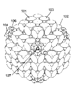
As will be seen in FIG. 10 some of the magnets 101 comprised in the lattice
configuration making up the magnet array 102 are larger first magnets 103 and
others
are smaller second magnets 106. The smaller second magnets form composite
magnets 104 at particular points in the array. As will be seen in FIG. 10, the
use of
such smaller second magnets 106 is exploited to provide a sample channel 107,
in this
case oriented along a body diagonal.
It will be understood that with the individual primary magnets 101 being in
the shape of
truncated cubes, and the lattice configuration being based on a simple cubic
lattice, a
magnet array 102 of the embodiment may be formed by forming and positioning
individual layers of individual magnets 101.
Broadly, a central layer is designated Layer 0 and comprises a vacant space
110 at its
center, forming the testing volume. FIG. 6A shows a plan view of Layer 0 of
the magnet
array of a first example of the first embodiment. It will be seen that these
magnets are
primary magnets and are "first magnets" as explained in the definitions
section of the
disclosure. Layer 0 is assembled in a support frame 150 having faces 151, 152
and
ends 153, 154, shown schematically in cross section in FIG. 6B. It will be
appreciated
that additional openings will be incorporated as required by a user to provide
for wiring
and other structures.
Layer 0 is bounded on a first side by a Layer 1, followed by a Layer 2, and
finally a
Layer 3. On the opposite side of Layer 0 the same arrangement extends in the
opposite
direction, with Layer -1, Layer -2, and Layer -3. It will be understood that
the array is
generally symmetrical. Each layer is assembled in a frame and the frames will
be
secured together to form an assembled array 102. Layer 1 is shown in FIG. 7B,
and it
24
Date Recue/Date Received 2020-12-07
will be seen that the central or testing volume is bounded on all sides and is
generally
cubic.
In embodiments the magnet array comprises a plurality of shimming magnets 120
associated with the array. In embodiments the shimming magnets occupy
positions
within lattice configuration and in embodiments are sized to be moveable
within the
array. In embodiments the shimming magnets 120 are polyhedral and are
comprised
within the magnet array. In embodiments the shimming magnets are positioned at
lattice
points within the array, and in embodiments are positioned outside the magnet
array. In
embodiments the shimming magnets are actuable by a user to move within the
magnet
assembly.
Individual magnets 101 comprising the magnet array are formed into an ordered
arrangement, and the arrangement includes shimming magnets 120, and composite
magnets 104 comprising smaller second magnets 106. The shimming magnets 120
are
slightly smaller than the other primary magnets 103, etc., permitting them to
be moved
as desired by a user, in order to effectively adjust the magnetic field in the
testing
volume. In embodiments, these magnets are individually moveable, or are
connected in
pairs or in pluralities. In embodiments the shimming magnets moved in the
plane of the
frame. The possible paths of movement in embodiments are designated by arrows,
125.
The magnets are mounted in frame 160. Channels 168 in the frame 160 are sized
to
accommodate shimming magnets 120 and to allow them to be moved.
The structure of Layers 2 is shown in FIGs. 8A & 8B. It will be seen that the
arrangement of this layer in an embodiment comprising primary magnets that are
truncated cubes is generally a square having five primary magnets 101 along
each side.
It will be seen that Layer 2 also comprises, at four positions, shimming
magnets 120. In
embodiments these are related in pairs to corresponding magnets in adjacent
layers.
Thus in the embodiment illustrated four shimming magnets in Layer 2 are
connected in
pairs to corresponding magnets in layer 3 of FIG 9. In these embodiments the
pairs of
shimming magnets together move into and out of the plane of the figure. It
will be
appreciated that in the illustrated embodiment, the array comprises seven
layers and
Date Recue/Date Received 2020-12-07
thus 24 pairs of magnets that are used for shimming. In embodiments shimming
magnets or electronic shims are provided in any suitable numbers. In
embodiments
shimming magnets or electronic shims are generally symmetrically arranged
around the
testing volume. In embodiments 1, 2, 3, 4, 5, 6, 7, 8, 9, 10, 11, 12, 13, 14,
15, 16, 17,
18, 19, 20, 21, 22, 23, 24, 25, 26, 27, 28, 29, 30, 31, 32, 33, 34, 35, 36,
37, 38, 39, 40,
41, 42, 43, 44, 45, 46, 47, 48 or more shims or shimming magnets are provided.
In
embodiments movement of the shimming magnets is coordinated in groups of 1, 2,
3, 4,
5, 6, 7, 8, 9 or more shimming magnets.
In embodiments there is also disclosed a method for shimming a magnetic field
generated by the magnet array according to embodiments. Generally, the method
comprises one or more steps. In embodiments the steps comprise: a) obtaining a
functional representation of the effect of moving the one of the plurality of
shimming
magnets on the magnetic field; b) repeating step a) for each one of the
plurality of
shimming magnets; c) deriving a sum function of the results of steps a) and
b); and
d) monitoring the magnetic field while adjusting the positions of ones of the
shimming
magnets.
The shimming magnets are provided as one means for "coarse" shimming the
magnetic
field within the testing volume. In embodiments the procedure for shimming
comprises
one or more or all of the following steps:
1) Obtain a functional representation of the effect on the magnetic field in
the testing
volume of moving a given one of the designated pairs of moveable magnets. A
suitable functional representation might take the form fii(x,y,z,iii), where
x, y,
and z denote the position coordinates within the testing volume where the
field is
to be estimated, and where i, represents a coordinate variable along which
shim
magnet i is permitted to move controllably. This functional representation can
be
obtained variously by magnetostatic simulations or by mapping the magnetic
field
changes that occur, for example with a gaussmeter probe, when magnet i is
moved along the coordinate r1i. Alternative functional representations and
means
for determining them will be readily understood by those skilled in the art.
26
Date Recue/Date Received 2020-12-07
2) Combine the functions I3 (x, y, z, into a sum function. In embodiments
the
usefulness of this sum function, as a representative of the effects on the
main
magnetic field depends in part on the extent to which the individual effects
are
independent, I. e. on the extent to which the magnetizations of the shim
magnets
and other magnets are resistant to changes induced by the motions. In
embodiments an important physical factor governing this resistance is the
coercivity of the magnetic materials used to fabricate both the shim magnets
and
the other component magnets in the array. It will be appreciated that in
embodiments use of high-coercivity magnetic materials is thus preferred.
3) In embodiments the sum function is then decomposed into component
functions,
in terms of both the spatial variables x, y, z and the magnet-coordinate
variables
7k. Alternatively, in embodiments, the magnet-coordinate variables i, can be
combined linearly into new variables
possibly adapted to the symmetry of the
shim-magnet positioning, and the sum function expressed in terms of both the
spatial variables x, y, z and the symmetry-adapted variables. Those skilled in
the
art of shimming will choose functional forms (polynomials, for example) in the
spatial variables x, y, z to suit the particular application.
4) In embodiments a response function of the magnetic field within the testing
volume is determined. In embodiments this response function might be a
magnetic field map or an NMR parameter, such as a resonance line width or may
be other functions which will be readily identified and selected amongst by
those
skilled in the art.
5) In embodiments a use will adjust or will iteratively adjust the positions
of the shim
magnets, and monitor changes in the response function, until a desired field
configuration is achieved. Those skilled in the art of shimming will use
improvements noted in the field or line-width data with each iterative change
in
order to modulate the main magnetic field as desired in applications. It will
be
understood that shimming magnets may be moved coordinately or separately as
desired by a user. Those skilled in the art will readily understand the
adjustments
that are necessary or desirable to optimize the foregoing adjustments to the
shimming magnets.
27
Date Recue/Date Received 2020-12-07
Those skilled in the art will recognize and implement a variety of ways to
achieve each
of the foregoing steps.
Returning now to the configuration of parts in FIGs. 8A and 8B, it will be
further seen
that at each of the corners of this layer there is situated a composite magnet
104
comprising a series of smaller or second magnets 106.
Layer 2 is mounted in a frame 170, having external face 171 and internal face
172, and
sloped edges 173, 174. Central region 175 comprises a recessed portion 178 on
internal face 172, and the periphery of the frame is thickened 176. Recessed
portion
178 fits snugly with the thickened central portion 165 of frame 160 holding
adjacent
layer 1. Openings 177 are provided to allow adjacent frames to be mutually
secured,
for example, with bolts.
Layers 3 are shown in plan view in FIG. 9A. It will be seen that Layer 3 is a
square with
three magnets along each side, comprising central primary magnets 101, and
four
shimming magnets again designated 120, at its corner positions. Again these
shimming
magnets are slightly smaller than the other primary magnets and can be moved
to shim
the primary field. The layer is assembled in frame 180 having sloped edges
183, 184,
an outer face 181 and an inner face 182 which will fit snugly with adjacent
frame 170.
Openings 187 are again provided to allow adjacent frames to be mutually
secured.
As will be seen in FIG. 10, the composite magnet positions comprising
composite
magnets 104 comprised of secondary magnets 106 allow the formation of a sample
channel 107 accessible from a corner of the array.
As indicated above, FIGS. 6A, 7A, 8A, and 9A show magnets in positions
constrained
by the frame, which is shown in plan view. FIGS. 6B, 7B, 8B, and 9B
respectively show
cross sectional end views of the respective frames for the layers illustrated.
The
framing materials will be selected by a user from a range of suitable
materials and in the
exemplary embodiment are made of any suitable material.
Openings are provided in the frames as necessary or desirable to accommodate
wires,
mountings, bolts, screws and the like and to permit access to the array as
required by a
28
Date Recue/Date Received 2020-12-07
user. It will be understood that in embodiments both primary and shimming
magnets
are unitary magnets and in alternative embodiments are composite magnets.
In one embodiment of the first series of embodiments the truncated cubic
primary
magnets or first magnets are about 1.250 inches face to face. The second
magnets,
which comprise composite magnets, are about 0.500 inches face to face. As a
result
the spaces between such smaller magnets will accommodate a 5 mm NMR tube down
a space or hole along the body diagonal of the main magnet array. The testing
volume
of the array is about the same size as one of the larger first or primary
magnets. It will
be understood that a range of sizes may be used and that the specific ratio of
sizes of
the first and second magnets will be adjusted by a user to suit particular
purposes.
While the first series of embodiments is illustrated and explained with
general reference
to primary magnets that are truncated cubes and a lattice that is a simple
cubic lattice, a
variety of other possible structures will be readily understood by those
skilled in the art.
Some examples of embodiments using different polyhedral shapes are presented
below.
A variety of alternative embodiments are possible, and illustrative variants
are
presented below. It will be understood that these are in no way limiting of
the subject
matter hereof.
Considerations regarding selectively removing subsets of the magnets, or
subsets of
the components of composite magnets, chamfering, affixing subsets of magnets
to
moveable structures in order to provide symmetry-adapted control over selected
field-
gradient functions, and shimming apply to all manner of alternative
embodiments and
variant embodiments. The possible variations and their implementation will be
readily
apparent to those skilled in the art who will select from and implement the
illustrative
variations and others, to suit particular requirements.
Those skilled in the art will recognize and implement changes to the geometry
of
frames, patterns of movement of the shimming magnets, any algorhithms and
calculations used, and any other variables that require adjustment to
accommodate
29
Date Recue/Date Received 2020-12-07
changes in the geometry of the array, the lattice structure, the magnets and
other
requirements. Those skilled in the art will also readily understand and
implement
modifications of embodiments to incorporate pole pieces and other refinements
to
further adjust the field in the testing volume.
Example
A first example of the first embodiment is explained with particular reference
to FIGS. 6
through 10 and is merely illustrative of embodiments and is in no way limiting
of the
subject matter claimed herein.
In this exemplary form of the first embodiment generally designated 102 and
shown in a
perspective view in FIG. 10 the primary magnets 101 are in the shape of
truncated
cubes. Some are unitary magnets 103 generally referred to herein as first
magnets,
and others are composite magnets 104 comprising multiple smaller second
magnets
106. The truncated cubes are disposed with their centers placed at the points
of a
simple cubic lattice as shown in FIG. 4A. If the lattice sites are labeled
with triads of
integers, e. g. [+1,0,0], [1,-2,0] etc., with each member of the triad
corresponding to a
coordinate of the lattice position according to three mutually perpendicular
Cartesian
axes, then we designate the lattice site at the center, [0,0,0], as the sample
location.
This location is vacant, containing no magnet, and constitutes the testing
volume, able
to contain a sample under study, a detection coil, temperature stabilization
or field
homogenizing means, a rotating device to spin the sample, and/or such other
components as may be desired by a user.
FIG. 10A is an exemplary block diagram of a magnetic resonance device 950 in
accordance with an embodiment of the invention. The device 950 comprises a
computer
951 operably connected to a sample rotation control module 952 for controlling
rotation
of an optional sample rotator 954 used for rotating a sample 956 within a
channel 958
provided in the magnet assembly/array 959. The computer 951 may also be
operably
connected to a pulsed magnetic field control and signal detection module 960
used for
controlling a detection coil 962 and receiving a signal therefrom. The device
950 may
also include a field homogeneity control module 964 for controlling the
magnetic field in
Date Recue/Date Received 2020-12-07
a centrally located lattice site 965 which is designed as the testing volume.
A
temperature control module 966 may also be provided for controlling the
temperature
inside the channel 958.
The magnetization of the magnet at site [x,y,z] may be selected to be the
closest unit
vector to the idealized magnetization direction
n't = (2(1) = fOr ¨ (r = r)-13)//-' = r,
consistent with the selection being within the finite set of vectors available
by rotating a
component magnet into one of the several orientations permitted by the
magnet's
insertion into the lattice. It will be understood that the position vector
r= a(xX + yj) + z2)
is calculable from the site indices x, y, and z, along the Cartesian axes
defining the
lattice and the lattice spacing, a. It will be appreciated that the set of
these several
orientations is made far more numerous by the fact that the component magnets
are
polyhedra of high symmetry rather than wedges or other oblique shapes.
Consequently
the array can be constructed using a limited number of component magnet
configurations. When assembling a magnet array a user may select from the set
of
possible orientations that orientation which, in combination with other
magnets in the
array, will give the best approximation of the desired primary magnetic field.
For
example a single primary magnet may have a dipole oriented in any of the three
directions illustrated in FIG. 11 and may be oriented in several different
ways within a
cubic lattice. Thus for a cubic array, the array may be assembled using only
three
components, namely individual magnets having one of the three dipole
orientations
shown in FIG. 11. It will be understood that the same principle may be applied
to a wide
range of other polyhedral shapes. It will also be understood that in
embodiments or
parts of embodiments a single magnet may be a unitary magnet or may be a
composite
magnet.
31
Date Recue/Date Received 2020-12-07
In this example symmetry is exploited and V is preferably oriented along a
body
diagonal, parallel to a face diagonal, or perpendicular to a face. In
particular
embodiments the field direction -V is oriented along a body diagonal of the
magnet array
and in particular embodiments is oriented perpendicular to a face of the
magnet array.
Again for maximum symmetry, the magnets are included in the assembly so that
all
members of a class are included. For example, the class [1,0,0] includes six
magnet
sites, namely [1,0,0], [0,1,0], [0,0,1], [-1,0,0], [0,-1,0], and [0,0,-1]. The
class [2,1,0]
includes 24 magnets corresponding to permutations of the numbers and changes
of
sign.
As will be seen in FIG. 10 some of the magnets 101 comprised in the lattice
configuration making up the magnet array 102 are larger first magnets 103 and
others
are smaller second magnets 106. The smaller second magnets form composite
magnets 104 at particular points in the array. As will be seen in FIG. 10, the
use of
such smaller second magnets 106 is exploited to provide a sample channel 107,
in this
case oriented along a body diagonal.
It will be understood that with the individual primary magnets 101 being in
the shape of
truncated cubes, and the lattice configuration being based on a simple cubic
lattice, a
magnet array 102 of the embodiment may be formed by forming and positioning
individual layers of individual magnets 101.
Broadly, a central layer is designated Layer 0 and comprises a vacant space
110 at its
center, forming the testing volume. FIG. 6A shows a plan view of Layer 0 of
the magnet
array of a first example of the first embodiment. It will be seen that these
magnets are
primary magnets and are "first magnets" as explained in the definitions
section of the
disclosure. Layer 0 is assembled in a support frame 150 having faces 151, 152
and
ends 153, 154, shown schematically in cross section in FIG. 6B. As will be
seen the
frame comprises a thinner central portion 155 and thicker periphery 156 and is
generally
octagonal. Holes 157 are included in the frame to allow the insertion of bolts
screws or
other supporting or securing structures. It will be appreciated that
additional openings
will be incorporated as required by a user to provide for wiring and other
structures.
32
Date Recue/Date Received 2020-12-07
Layer 0 is bounded on a first side by a Layer 1, followed by a Layer 2, and
finally a
Layer 3. On the opposite side of Layer 0 the same arrangement extends in the
opposite
direction, with Layer -1, Layer -2, and Layer -3. It will be understood that
the array of
this example of the embodiment is generally symmetrical. Each layer is
assembled in a
frame and the frames will be secured together to form an assembled array 102.
Layer 1 is shown in FIG. 7B, and it will be seen that inner layers 1 and -1
align with
central Layer 0 but lack the central cavity, and thus the central or testing
volume is
bounded on all sides and is generally cubic.
Individual magnets 101 are formed into an ordered arrangement, and the
arrangement
includes shimming magnets 120, which are distinguished by stippling, and
composite
magnets 104 comprising smaller second magnets 106. The shimming magnets 120
are
slightly smaller than the other primary magnets 103, etc., permitting them to
be moved
as desired by a user, in order to effectively adjust the magnetic field in the
testing
volume. In the embodiment, these magnets are connected in pairs and can be
moved
in the plane of the frame along paths designated by arrows, 125.
The magnets are mounted in frame 160 having edges 163, 164, top and bottom
surfaces 161, 162, a thickened central portion 165 and thinner periphery 166.
Channels
168 are sized to accommodate shimming magnets 120 and to allow them to be
moved
as described herein, to shim the primary magnetic field of the assembled
array. It will
be appreciated that holes 167 are comprised in the frame to allow adjacent
frames to be
mutually secured, and that additional openings will be introduced by a user to
accommodate wires and the like.
The structure of Layers 2 is shown in FIGs. 8A and 8B. It will be seen that
the
arrangement of this layer is generally a square having five primary magnets
101 along
each side. It will be seen that Layer 2 also comprises, at four positions,
shimming
magnets 120. These shimming magnets are slightly smaller than the other
primary
magnets 101, permitting them to be moved as desired by a user, in order to
effectively
adjust the magnetic field in the testing volume. These four magnets are
connected in
pairs to corresponding magnets in layer 3 of FIG 9, and the pairs together
move into
33
Date Recue/Date Received 2020-12-07
and out of the plane of the figure. It will be appreciated that the seven
layers of an
assembled array together comprise 24 pairs of magnets that are used for
shimming.
The 24 pairs of moveable magnets in this first embodiment illustrate the
potential for
"coarse" shimming the magnetic field within the testing volume. A
representative
procedure for said shimming would proceed in steps as follows:
1) Obtain a functional representation of the effect on the magnetic field in
the testing
volume of moving a given one of the designated pairs of moveable magnets. A
suitable functional representation might take the form 14 i(x, y, where x,
y,
and z denote the position coordinates within the testing volume where the
field is
to be estimated, and where i, represents a coordinate variable along which
shim
magnet i is permitted to move controllably. This functional representation can
be
obtained variously by magnetostatic simulations or by mapping the magnetic
field
changes that occur, for example with a gaussmeter probe, when magnet i is
moved along the coordinate Th.
2) Combine the functions I3 (x, y, z, ) into a sum function. The usefulness of
this
sum function, as a representative of the effects on the main magnetic field
depends in part on the extent to which the individual effects are independent,
I. e.
on the extent to which the magnetizations of the shim magnets and other
magnets are resistant to changes induced by the motions. The principal
physical
factor governing this resistance is the coercivity of the magnetic materials
used to
fabricate both the shim magnets and the other component magnets in the array.
It will be appreciated that use of high-coercivity magnetic materials is thus
preferred.
3) The sum function can then be decomposed into component functions, in terms
of
both the spatial variables x, y, z and the magnet-coordinate variables Th.
Alternatively, the magnet-coordinate variables i, can be combined linearly
into
new variables possibly adapted to the symmetry of the shim-magnet
positioning, and the sum function expressed in terms of both the spatial
variables
x, y, z and the symmetry-adapted variables. Those skilled in the art of
shimming
34
Date Recue/Date Received 2020-12-07
will choose functional forms (polynomials, for example) in the spatial
variables x,
y, z to suit the particular application.
4) Measure a response function of the magnetic field to be shimmed within the
testing volume. This response function might be a magnetic field map or an
NMR parameter, such as a resonance line width.
5) Iteratively adjust the positions of the shim magnets, and monitor changes
in the
response function, until a desired field configuration is achieved. Those
skilled in
the art of shimming will use improvements noted in the field or line-width
data
with each iterative change in order to modulate the main magnetic field as
desired in applications. It will be understood that shimming magnets may be
moved coordinately or separately as desired by a user.
Returning now to the configuration of parts in FIGs. 8A and 8B, it will be
further seen
that at each of the corners of this layer there is situated a composite magnet
104
comprising a series of smaller or second magnets 106.
Layer 2 is mounted in a frame 170, having external face 171 and internal face
172, and
sloped edges 173, 174. Central region 175 comprises a recessed portion 178 on
internal face 172, and the periphery of the frame is thickened 176. Recessed
portion
178 fits snugly with the thickened central portion 165 of frame 160 holding
adjacent
layer 1. Openings 177 are provided to allow adjacent frames to be mutually
secured,
for example, with bolts.
Layers 3 are shown in plan view in FIG. 9A. It will be seen that Layer 3 is a
square with
three magnets along each side, comprising central primary magnets 101, and
four
shimming magnets again designated 120, at its corner positions. Again these
shimming
magnets are slightly smaller than the other primary magnets and can be moved
to shim
the primary field. The layer is assembled in frame 180 having sloped edges
183, 184,
an outer face 181 and an inner face 182 which will fit snugly with adjacent
frame 170.
Openings 187 are again provided to allow adjacent frames to be mutually
secured.
Date Recue/Date Received 2020-12-07
As will be seen in FIG. 10, the composite magnet positions comprising
composite
magnets 104 comprised of secondary magnets 106 allow the formation of a sample
channel 107 accessible from a corner of the array.
As indicated above, FIGS. 6A, 7A, 8A, and 9A show magnets in positions
constrained
by the frame, which is shown in plan view. FIGS. 6B, 7B, 8B, and 9B
respectively show
cross sectional end views of the respective frames for the layers illustrated.
The
framing materials will be selected by a user from a range of suitable
materials and in the
exemplary embodiment are made of any suitable material.
Openings are provided in the frames as necessary or desirable to accommodate
wires,
mountings, bolts, screws and the like and to permit access to the array as
required by a
user. In the example both primary and shimming magnets are unitary magnets. In
alternative embodiments it will be understood that composite magnets can also
be
used.
In this example of the first embodiment the truncated cubic primary magnets or
first
magnets are about 1.250 inches face to face. The second magnets, which
comprise
composite magnets, are about 0.500 inches face to face. As a result the spaces
between such smaller magnets will accommodate a 5 mm NMR tube down a space or
hole along the body diagonal of the main magnet array. The testing volume of
the array
is about the same size as one of the larger first or primary magnets.
In this example of the frames used to support and organize the component
magnets are
made from any suitable material. Suitable materials in particular applications
include
aluminum, brass, or a strong plastic such as PEEKTM or DelrinTM, or a ceramic
material
such as MacorTM. Those skilled in the art will readily identify and implement
a range of
possible alternatives.
In this example the magnets themselves are made from any suitable material.
High
coercivity materials are suitable, as are strong rare-earth based magnets.
Exemplary
possibilities are neodymium-iron-boron and samarium-cobalt alloys. Those
skilled in
the art will readily identify and implement a range of possible alternatives.
36
Date Recue/Date Received 2020-12-07
In embodiments of this example a field in the range of 1.0 to 2.5 Tesla is
achievable,
however the field strength of any particular embodiment will depend on the
number of
layers of lattice sites, the strength of the individual component magnets, the
presence
and types of pole piece and construction materials used and other variables.
Those
skilled in the art will understand all such variables and make suitable
allowances
therefore.
Pole pieces are not illustrated being part of the general common knowledge in
the art. It
will be understood that those skilled in the art may wish to incorporate pole
pieces into
the array of the example order to further modify the field. In modifications
of the
example that contain pole pieces incorporated in the array to shim the
magnetic field in
the testing volume, it has been found that suitable materials for such pole
pieces include
HipercoTm , soft iron materials, or other suitable materials, all of which
will be readily
identified and utilized by those skilled in the art.
Second Embodiment
In one alternative embodiment generally designated 130 and illustrated in FIG.
13A, the
primary magnets 131 of the magnet array 130 are rhombic dodecahedra which
shape is
illustrated in FIG 5N.
FIG. 13A illustrates an array based on this configuration in exploded view and
FIG. 13B
illustrates a central layer of such an array. The rhombic dodecahedra are
configured in
layers 520, 540, 560, each of which is based on a triangular, 2-dimensional
lattice of
points. The central layer 520 is bounded by first layers 540 and 540', and
then second
layers 560 and 560'. The 2-dimensional lattices together comprise a face-
centered
cubic lattice. Again, the central layer comprises a lattice site, centrally
located,
designated as the testing volume 132. In embodiments, the rhombic dodecahedra
may
be chamfered, or the lattice expanded, to permit access to the central testing
volume.
The overall nature of the arrangement and the configuration of any structural
supports
or frames will be readily understood by those skilled in the art, using the
same principles
as the Example of the First Embodiment.
37
Date Recue/Date Received 2020-12-07
Third Embodiment
A third alternative embodiment is shown in FIG. 14 and is generally designated
600.
The magnet array 600 shown in FIG. 14 is based on a space-filling structure
consisting
solely of cubes 601 in a portion of a simple cubic lattice. The central cube
is removed to
provide the central cavity or testing volume 604. The lattice is expanded, and
cubes on
the corners of the structure (eight in number) are removed to accommodate a
sample-
tube, which is not illustrated. If a vector normal to a face of this block is
chosen as the
(colatitude) 0 = 0 axis of a spherical coordinate system and magnetizations
are chosen
according to the equation explained above, then the sample-tube entry axis
will be at
the "magic angle" with respect to the uniform field axis in the central
cavity.
Fourth Embodiment
A fourth alternative embodiment is shown in FIG. 15 and is generally
designated 620.
In this embodiment the design 600 of FIG.14 is supplemented with square
parallelepipeds 621. In embodiments this provides a higher field strength
within the
central cavity and a coarse-shimming capability if the outer elements are
affixed to
moveable structures. Those skilled in the art will readily understand how to
frame and
articulate the magnets to achieve desired aims.
Fifth Embodiment
A fifth alternative embodiment is shown in FIG. 16 and is generally designated
71. As in
the design of FIG. 17A, the magnet block 711 of this embodiment is based on a
space-
filling structure consisting of portions of four interpenetrating face-
centered cubic (fcc)
lattices, but with different polyhedra. Truncated cuboctahedra occupy the
corners 712
and face-centers 713 of the magnet-block 711, and truncated cubes are placed
at the
edge-centers 714, with the central truncated cube removed to provide the
central cavity.
These two lattices are supplemented by two other fcc lattices, each of whose
sites are
occupied by truncated tetrahedra 715, which are present in two different
orientations.
If the edge-centered truncated cubes 714 are removed and the lattices are
expanded to
the degree necessary, and if the interior-most truncated tetrahedra are made
smaller or
38
Date Recue/Date Received 2020-12-07
are chamfered, then a channel is created, which can be used as an access port
to the
interior of the structure. Alternatively, holes can be drilled through either
the truncated
cuboctahedra or the truncated cubes to accommodate the insertion of a sample
tube.
In this case, if the truncated cubes are affixed to structures that permit
their movement
toward and away from the center of the assembly, a coarse-shimming capability
can be
realized. This coarse-shimming capability will have twelve degrees of freedom,
and
these twelve individual motions can be combined into concerted motions of all
twelve
magnets, which can facilitate assignment of the motions to particular
functional
components (e.g., x, yz, y2 ¨ z2, etc.) of field gradients to be shimmed based
on
symmetry considerations.
Sixth Embodiment
A further embodiment is shown in FIGs. 17A and 17B and is generally designated
800.
FIG. 17A shows an embodiment generally designated 800 for a magnet array 801
based on a space-filling structure consisting of portions of four
interpenetrating face-
centered cubic lattices. Truncated octahedra 802 occupy the corners 803 and
face-
centers 804 of the magnet-block shown. Cuboctahedra 805 are placed at the edge-
centers, and then the central cuboctahedron is removed 808 in order to provide
a
central cavity for a sample, NMR detection coil, electronic field-shimming
measures,
sample spinner, or other apparatus. These two lattices are supplemented by two
other
lattices, each of whose lattice sites are occupied by truncated tetrahedra 809
(in two
different orientations).
FIG. 17B shows how a sample channel can be incorporated into the array if the
edge-
centered cuboctahedra 805 are removed and the lattices are expanded to the
degree
necessary, or if the interior-most truncated tetrahedra 810 are made smaller
or are
chamfered. Alternatively, holes can be drilled through the cuboctahedra to
accommodate the insertion of a sample tube. In this case, if the cuboctahedra
are
affixed to structures that permit their movement toward and away from the
center of the
assembly, a coarse-shimming capability can be realized. This coarse-shimming
capability will have twelve degrees of freedom, and these twelve individual
motions can
39
Date Recue/Date Received 2020-12-07
be combined into concerted motions of all twelve magnets, which can facilitate
assignment of the motions to particular functional components (e.g., x, yz, y2
¨ z2, etc.)
of field gradients to be shimmed based on symmetry considerations.
Further Embodiments
Further alternative embodiments are shown in FIGs. 18A-18D. For clarity, only
portions
of the lattice configurations are shown. It will be understood that, as with
the first
embodiment, the lattice configurations can be defined by choosing from the
infinite point
sets defining the underlying lattices those points nearest a designated
"origin" point,
[0,0,0] within a neighborhood defined by a maximum radius. The points chosen
for the
lattice configuration will generally include all those generated from a given
point by
considerations of symmetry. That is, for example, inclusion of the lattice
point [3,2,0]
will induce inclusion of the symmetry-related points in the whole class
[3,2,0], that is, the
points [3,-2,0], [3,0,2], [3,0,-2], [2,3,0], [2,-3,0], and all others, for a
total of 24 in number,
obtained by permuting the numbers and changing signs. It will further be
understood
that some of those classes of points will be excluded from the lattice
configuration in
order to facilitate access to the testing volume.
FIG. 18A shows an embodiment of a magnet array generally designated 73
comprising
two interpenetrating simple cubic lattices, one with truncated cubes 731 and
one with
octahedra 732.
FIG. 18B shows an embodiment of a magnet array generally designated 75
comprising
four interpenetrating face-centered cubic lattices, one with
rhombicuboctahedra 751,
one with cubes 752, and two with tetrahedra 753 in each of two orientations.
The latter
components are not shown in this illustration.
FIG. 18C shows an embodiment of a magnet array generally designated 72
comprising
five interpenetrating simple cubic lattices, one with truncated cuboctahedra
721, one
with truncated octahedra 723, and three with cubes 722 in each of three
orientations.
Date Recue/Date Received 2020-12-07
FIG. 18D shows an embodiment of a magnet array generally designated 74
comprising
five interpenetrating simple cubic lattices, one with cuboctahedra 741, one
with
rhombicuboctahedra 742, and three with cubes 743 in each of three
orientations.
The embodiments and examples presented herein are illustrative of the general
nature
of the subject matter disclosed and claimed and are not limiting. It will be
understood by
those skilled in the art how these embodiments can be readily modified and/or
adapted
for various applications and in various ways. Phrases, words and terms
employed
herein are illustrative and are not limiting. It will be appreciated that any
aspects of the
different embodiments disclosed herein may be combined in a range of possible
alternative embodiments, and alternative combinations of features, all of
which varied
combinations of features are to be understood to form a part of the subject
matter
claimed. Particular embodiments may alternatively comprise or consist of or
exclude
any one or more of the elements disclosed.
41
Date Recue/Date Received 2020-12-07