Language selection

Search

Patent 2914183 Summary

Third-party information liability

Some of the information on this Web page has been provided by external sources. The Government of Canada is not responsible for the accuracy, reliability or currency of the information supplied by external sources. Users wishing to rely upon this information should consult directly with the source of the information. Content provided by external sources is not subject to official languages, privacy and accessibility requirements.

Claims and Abstract availability

Any discrepancies in the text and image of the Claims and Abstract are due to differing posting times. Text of the Claims and Abstract are posted:

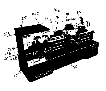
  • At the time the application is open to public inspection;
  • At the time of issue of the patent (grant).
(12) Patent Application: (11) CA 2914183
(54) English Title: NON-SLIP MAT FOR LATHE
(54) French Title: TAPIS ANTIDERAPANT POUR TOUR
Status: Deemed Abandoned and Beyond the Period of Reinstatement - Pending Response to Notice of Disregarded Communication
Bibliographic Data
(51) International Patent Classification (IPC):
  • B23B 25/00 (2006.01)
(72) Inventors :
  • GARDNER, MARTIN (United States of America)
  • WEBER, CHARLES (United States of America)
  • CARLSON, BENJAMIN (United States of America)
(73) Owners :
  • JPW INDUSTRIES INC.
(71) Applicants :
  • JPW INDUSTRIES INC. (United States of America)
(74) Agent: SMART & BIGGAR LP
(74) Associate agent:
(45) Issued:
(22) Filed Date: 2015-12-07
(41) Open to Public Inspection: 2016-06-08
Availability of licence: N/A
Dedicated to the Public: N/A
(25) Language of filing: English

Patent Cooperation Treaty (PCT): No

(30) Application Priority Data:
Application No. Country/Territory Date
14/959,957 (United States of America) 2015-12-04
62/088,835 (United States of America) 2014-12-08

Abstracts

English Abstract


A lathe or other rotating machine includes a chuck for holding a work piece or
tool.
The chuck is operated between grasping and releasing positions. At least one
non-slip mat
rests on the housing of the rotating machine, including raised edges.


Claims

Note: Claims are shown in the official language in which they were submitted.

WE CLAIM AS OUR INVENTION:
1. A rotating machine, comprising:
a housing;
a motor that is operable for rotational motion;
a chuck connected for rotation by the motor, the chuck including grasping
elements that are
movable relative to a rotational center of the chuck; and
at least one non-slip mat resting on a horizontal surface of the housing.
2. The rotating machine as claimed in claim l wherein a plurality of non-slip
mats are
resting on a plurality of respective horizontal surfaces of the rotating
machine.
3. The rotating machine as claimed in claim 1 wherein the horizontal surface
on
which the least one non-slip mat is resting is at a location of the housing
adjacent to and
above the chuck.
4. The rotating machine as claimed in claim I wherein the horizontal surface
on
which the at least one non-slip mat is resting at a location of the housing
adjacent to and near
a bottom of the chuck.
5. The rotating machine as claimed in claim 1 wherein the non-slip mat
comprises a
non-slip rubber material.
6. The rotating machine as claimed in claim 1 wherein the non-slip mat has at
least
one protrusion at a bottom of the mat to promote non-slipping of the mat and
to support an
upper surface of the mat.
7. The rotating machine as claimed in claim 6 wherein a plurality of
protrusions are
provided at the bottom.
6

8. The rotating machine as claimed in claim 1 wherein a periphery of the mat
at
outside edges of the mat comprise raised ribs.
9. The rotating machine as claimed in claim 8 wherein additional raised ribs
are
provided interiorly of the edges to define a plurality of separate spaces.
10. The rotating machine as claimed in claim 9 wherein at least one of the
separate
spaces has projections having a height smaller than a height of the raised
ribs.
11. The rotating machine as claimed in claim 9 wherein at least one of the
separate
spaces has elongated oval shaped projections.
12. The rotating machine as claimed in claim 1 wherein the at least one non-
slip mat
has an oval hanging lip over-hanging a leading edge of said horizontal surface
where said mat
is resting.
7

Description

Note: Descriptions are shown in the official language in which they were submitted.


CA 02914183 2015-12-07
SPECIFICATION
TITLE
"NON-SLIP MAT FOR LATHE"
RELATED APPLICATION
The present application claims the benefit of the filing date of provisional
application
62/088,835, filed December 8, 2014 titled "CHUCK GUARD AND NON-SLIP MAT FOR
LATHE", inventors Gardner et al.
BACKGROUND
Field
[0001] The present invention relates generally to a lathe or other rotating
machine,
and more particularly to an item resting surface for a lathe or other rotating
machine.
Description of the Related Art
[0002] A lathe holds a work piece from one or both ends as the work piece
is rotated
at relatively high speed. Tools such as cutting and shaping tools are moved
into contact with
the rotating work piece to shape the work piece. A lathe is commonly used to
form spindles,
table legs, chair legs, crank shafts, and other rotationally formed portions,
which are held
from both ends. A lathe may also be used to form bowls or the like by mounting
the work
piece so that it is held at a single end.
[0003] Lathes may be used to shape wood, metal, or other materials. The
work piece
materials are supported by a chuck that is connected to a motor which operates
to rotate the
chuck and the work piece, typically at high speed. The work piece is engaged
in the chuck by
adjusting the chuck to engage the work piece so that the work piece may be
shaped, and the
work piece is released from the chuck by adjusting the chuck so that the
shaped work piece
may be removed from the lathe. The chuck typically includes grasping elements
that move
toward and away from one another symmetrically about the rotational center of
the chuck.
The grasping elements may be moved using a tool referred to as a chuck key.
The chuck key
is inserted into a key receiving opening on the chuck and is rotated to
operate gear
mechanisms within the chuck that move the grasping elements.
1

CA 02914183 2015-12-07
[0004] In addition to lathes, drills, drill presses, routers, cutting,
sanding and shaping
tools, powered screw drivers and wrenches and other tools may have chucks. In
drills, drill
presses, and the like, the chuck is operable to hold a tool, such as a drill
bit.
SUMMARY OF THE INVENTION
[0005] The lathe according to certain embodiments includes at least one non-
slip mat
mounted on the housing. The non-slip mat is preferably on a horizontal surface
of the
housing, although the mat location is not limited to horizontal surfaces. The
non-slip mat of
certain embodiments is on a top of a portion of the housing adjacent the
chuck, and in certain
embodiments adjacent the chuck. Other surfaces of the lathe housing may
include non-slip
mats as well.
[0006] The mat provides a surface for placing items such as tools, work
pieces or
other parts or elements. The mat prevents vibration of the items or parts on
the mat from
vibrating, providing quieter operation. The mat provides sound damping as
well.
BRIEF DESCRIPTION OF THE DRAWINGS
[0007] Figure 1 is a perspective view of a lathe of a type that includes
one or more
non-slip mats for holding items;
[0008] Figure 2 is a partial perspective view of a portion of the lathe of
Figure 1
showing first and second non-slip mats;
[0009] Figure 3 is another perspective view of the non-slip first and
second mats of
Figure 2 and lying on respective horizontal surfaces;
[0010] Figure 4 is atop view of the second mat on a horizontal surface
adjacent and
near a bottom of the chuck of the lathe;
[0011] Figure 5 is an end view of the second mat;
[0012] Figure 6 is a perspective view showing the second mat in the
orientation
shown in Figure 5;
2

CA 02914183 2015-12-07
[0013] Figure 7 is a top view of the first mat arranged on a surface of the
housing
adjacent to and above the chuck;
[0014] Figure 8 is an end view of the first mat shown in Figure 7;
[0015] Figure 9 is a perspective view of the first mat of Figure 7;
[0016] Figure 10 is a bottom plan view of the first mat of Figure 7; and
[0017] Figure 11 is a cross-sectional view of the first mat of Figure 7
taken along
cross-sectional line X-X in Figure 7 and in Figure 10.
DETAILED DESCRIPTION OF THE PREFERRED EMBODIMENTS
[0018] In Figure 1, a lathe 10 includes a housing 12 within which is
mounted a motor
(not shown) that drives a chuck or headstock 14 that holds a work piece. The
lathe 10
includes a bed 16 on which is mounted a carriage 18 and at the end of which is
mounted a
tailstock 20. Controls 22A, 22B, 22C for the operation of the lathe 10 are
provided on the
housing 12.
[0019] The housing 12 of the lathe 10 includes horizontal surfaces 24A and
24B on
which may be placed tools, parts, work pieces or other items. The horizontal
surfaces 24A
and 24B are provided with first and second respective non-slip mats 25 and 26
in certain
embodiments. The housing 12 also includes an emergency break 60 on which a
user may
place a foot.
[0020] Turning to Figure 2, the non-slip mats 25 and 26 are provided on the
respective horizontal surfaces 24A and 24B of the housing 12. The non-slip mat
25 includes
raised ribs 40 that extend upward interiorly and also at the edges to prevent
items from rolling
or vibrating off. The spaces 42A, 42B, 42C, 42D, 42E defined by the ribs 40
may be smooth
or textured. In the illustrated embodiment, some of the spaces 42A and 42B
include ridges 44
to prevent inadvertent movement of items placed on the mat 25.
[0021] Surface 24B comprises a small shelf 46 provided on the housing 12,
the shelf
46 being provided with the second non-slip mat 26, that is somewhat similar in
structure to
the mat 25 on the top surface 24A. Raised edges, dividing ribs and ridges 48
are provided
3

CA 02914183 2015-12-07
defining spaces 60A and 60B on the non-slip mat 26. Either or both mats 25 and
26 may be
provided with raised portions 49 such as dots or circles, or other shapes such
as an elongated
oval shape as illustrated. Both mats 25 and 26 are of a soft, pliable
material, such as rubber
or the like, that avoids vibration of items placed on the mats and creates at
least in part a non-
slip characteristic of the mats.
[0022] Figure 3 shows in perspective the first and second mats 25 and 26
from a
different perspective direction for clarity of viewing.
[0023] Figure 4 shows a plan view of the second mat 26 with the elongated
oval
raised portions 49 aligned within the space 60A defined by the surrounding
raised rib 48.
Also the space 60B defined by the raised rib 48 does not have raised portions
49.
[0024] Figure 5 shows an end view of the second mat 26 with a main flat
portion 53
for lying on the surface 24B and an overhanging lip portion 54 which overlies
a front edge of
the surface 24B. A perspective view showing the shape is illustrated in Figure
6. A
protrusion 55 runs almost an entire length of the mat and provides support for
a top surface of
the mat 26.
[0025] Figure 7 shows a plan view of the first mat 25 for ease of viewing.
[0026] Figure 8 shows an end view of the first mat 25 in which a tapered
portion 53
is illustrated at the front end of the mat 25.
[0027] Figure 9 shows a perspective view of the first mat 25 also shown in
Figure 7.
[0028] Figure 10 is a plan view of a bottom of the mat 25 showing raised
ribs 56
defining pockets 57 on the bottom of mat 25. These raised ribs 56 as
protrusions together
with the material used for the mat, which is preferably rubber, result in the
non-slip
characteristics of the mat 25. The raised ribs 56 also support a top surface
of the mat 25.
[0029] Figure 11 shows a cross-sectional view taken along line X-X in
Figures 7
and 10.
4

CA 02914183 2015-12-07
[0030] Thus there is shown and described one or more non-slip mats which
may be
provided on the lathe, such as on horizontal surfaces.
[0031] Although other modifications and changes may be suggested by those
skilled
in the art, it is the intention of the inventors to embody within the patent
warranted hereon all
changes and modifications as reasonably and properly come within the scope of
their
contribution to the art..

Representative Drawing
A single figure which represents the drawing illustrating the invention.
Administrative Status

2024-08-01:As part of the Next Generation Patents (NGP) transition, the Canadian Patents Database (CPD) now contains a more detailed Event History, which replicates the Event Log of our new back-office solution.

Please note that "Inactive:" events refers to events no longer in use in our new back-office solution.

For a clearer understanding of the status of the application/patent presented on this page, the site Disclaimer , as well as the definitions for Patent , Event History , Maintenance Fee  and Payment History  should be consulted.

Event History

Description Date
Application Not Reinstated by Deadline 2022-03-01
Inactive: Dead - RFE never made 2022-03-01
Letter Sent 2021-12-07
Deemed Abandoned - Failure to Respond to Maintenance Fee Notice 2021-06-07
Deemed Abandoned - Failure to Respond to a Request for Examination Notice 2021-03-01
Letter Sent 2020-12-07
Common Representative Appointed 2020-11-07
Common Representative Appointed 2019-10-30
Letter Sent 2018-01-03
Reinstatement Requirements Deemed Compliant for All Abandonment Reasons 2017-12-21
Deemed Abandoned - Failure to Respond to Maintenance Fee Notice 2017-12-07
Inactive: Cover page published 2016-06-20
Application Published (Open to Public Inspection) 2016-06-08
Inactive: IPC assigned 2016-01-15
Inactive: First IPC assigned 2016-01-15
Inactive: Filing certificate - No RFE (bilingual) 2015-12-11
Application Received - Regular National 2015-12-10

Abandonment History

Abandonment Date Reason Reinstatement Date
2021-06-07
2021-03-01
2017-12-07

Maintenance Fee

The last payment was received on 2019-12-02

Note : If the full payment has not been received on or before the date indicated, a further fee may be required which may be one of the following

  • the reinstatement fee;
  • the late payment fee; or
  • additional fee to reverse deemed expiry.

Patent fees are adjusted on the 1st of January every year. The amounts above are the current amounts if received by December 31 of the current year.
Please refer to the CIPO Patent Fees web page to see all current fee amounts.

Fee History

Fee Type Anniversary Year Due Date Paid Date
Application fee - standard 2015-12-07
Reinstatement 2017-12-21
MF (application, 2nd anniv.) - standard 02 2017-12-07 2017-12-21
MF (application, 3rd anniv.) - standard 03 2018-12-07 2018-11-22
MF (application, 4th anniv.) - standard 04 2019-12-09 2019-12-02
Owners on Record

Note: Records showing the ownership history in alphabetical order.

Current Owners on Record
JPW INDUSTRIES INC.
Past Owners on Record
BENJAMIN CARLSON
CHARLES WEBER
MARTIN GARDNER
Past Owners that do not appear in the "Owners on Record" listing will appear in other documentation within the application.
Documents

To view selected files, please enter reCAPTCHA code :


To view images, click a link in the Document Description column. To download the documents, select one or more checkboxes in the first column and then click the "Download Selected in PDF format (Zip Archive)" or the "Download Selected as Single PDF" button.

List of published and non-published patent-specific documents on the CPD .

If you have any difficulty accessing content, you can call the Client Service Centre at 1-866-997-1936 or send them an e-mail at CIPO Client Service Centre.


Document
Description 
Date
(yyyy-mm-dd) 
Number of pages   Size of Image (KB) 
Description 2015-12-06 5 159
Drawings 2015-12-06 9 578
Abstract 2015-12-06 1 7
Claims 2015-12-06 2 43
Representative drawing 2016-05-10 1 39
Courtesy - Abandonment Letter (Maintenance Fee) 2018-01-02 1 175
Notice of Reinstatement 2018-01-02 1 165
Filing Certificate 2015-12-10 1 179
Reminder of maintenance fee due 2017-08-07 1 113
Commissioner's Notice: Request for Examination Not Made 2020-12-28 1 540
Commissioner's Notice - Maintenance Fee for a Patent Application Not Paid 2021-01-17 1 537
Courtesy - Abandonment Letter (Request for Examination) 2021-03-21 1 554
Courtesy - Abandonment Letter (Maintenance Fee) 2021-06-27 1 552
Commissioner's Notice - Maintenance Fee for a Patent Application Not Paid 2022-01-17 1 552
New application 2015-12-06 3 100