Note: Descriptions are shown in the official language in which they were submitted.
88587063
APPARATUS FOR FRAC BALL CATCHING
Cross-Reference to Related Applications
This application claims priority from Canadian Patent Application 2,876,603,
filed Jan. 6, 2015.
Technical Field
100011 This disclosure relates in general to an apparatus for oil and gas
recovery and, in
particular, to an improved apparatus for ball catching during oil and gas
recovery operations.
Background of the Disclosure
[0002] Hydraulic fracturing (also referred to as fracking) is a technique
used to improve
recovery rates in oil and gas wells. Typically, fracking involves pumping a
fluid containing a
proppant (e.g. sand, ceramic beads) down the well and into the formation from
which oil or gas
is to be recovered. The fluid creates or enlarges fissures in the formation,
and the proppant
prevents the fissures from closing when pumping of the fluid ceases. After the
pumping of
fracking fluid down the well ceases, well fluid, which may contain oil or gas,
is allowed to flow
up the well for recovery.
[0003] In some well operations, it is desirable to isolate different zones
of the formation
through which the well extends before pumping fracturing fluid down the well,
in order to
fracture only a particular zone. The above-mentioned isolation is often
achieved by inserting frac
balls into the well. The frac balls, carried down the well by the fracturing
fluid, seal against seats
within the well casing, and actuate devices which restrict the fracturing
fluid contact to only the
1
Date recue / Date received 2021-12-06
CA 02914430 2015-12-09
desired portion or stage of the well. Once the fracking operation is complete,
the well fluid
flowing up the well carries the frac balls with it.
[0004] When the well fluid and frac balls reach the frac tree connected to
the top of the well,
they are directed to a ball catcher mechanism, which generally includes a
horizontal member
extending from the well, and a vertical chamber depending from the horizontal
member. The
well fluid and frac balls flow from the well through the horizontal member,
and the frac balls fall
into the vertical chamber while well fluid flows to downstream equipment. The
ball catcher can
then be isolated from the horizontal member and the balls can be recovered.
[0005] In known solutions of separating debris and/or balls from a fluid
flow, a screen or
filter is used within the flow line to catch the debris and/or balls. This
screen or filter may be
designed with holes that are small enough to prevent debris and/or balls from
passing and thus
removing the debris and/or balls from the fluid flow. Some prior art designs
exist which allow
for removal of debris and/or balls from the screen without stopping the fluid
flow.
[0006] For example, U.S. Patent No. 2,977,616 discloses a pig ball receiver
20 adapted to
receive or recover a pig ball 21 from a flow line 22 as shown in FIGS. 1 and
2. The principal
purpose of the pig ball 21 is to remove deposits from the walls of the flow
line 22. FIG. 1 shows
the pig ball receiver 20 with a valve 23 in a first position for receiving the
pig ball 21. FIG. 2
shows the pig ball receiver 20 with the valve 23 in a second position for
preventing flow into a
receiver housing 24 to allow for removal of the pig ball 21.
[0007] As another example, Canadian patent 2,635,852 discloses a ball
catcher 25 fluidly
connected to a wellhead port 26 to receive well bore fluids and balls 27
carried therewith, as
2
88587063
shown in FIG. 3. The ball catcher 25 includes an isolation valve 28 to isolate
the ball recovery
chamber 29 temporarily from the catcher body 30 for servicing.
Summary
[0008] In an aspect, there is provided an apparatus for ball catching. The
apparatus includes
a body having an inlet for receiving fluid and at least one ball, a fluid
outlet for permitting fluid
to exit the body, and a ball-collection outlet for accommodating at least one
ball. The apparatus
further includes a chamber in communication with the ball-collection outlet,
the chamber for
receiving at least one ball. In addition, the apparatus includes a rotatable
plug disposed within
the body, the rotatable plug having at least three channels in communication
with each other,
wherein each of the three channels is configured to align with the inlet, the
fluid outlet and the
ball-collection outlet. Furthermore, the apparatus includes a blockage
disposed within one of the
at least three channels, the blockage configured to prevent the passage of at
least one ball and
permit the passage of fluid, wherein the rotatable plug is rotatable between a
first position in
which at least one ball is permitted to enter the body and is prevented from
exiting the body and
in which fluid is permitted to enter and exit the body, a second position in
which fluid is
prevented from exiting the body, and a third position in which fluid is
permitted to enter and exit
the body and is prevented from entering the chamber.
[00091 In certain embodiments, the apparatus may include a wing valve
connected to the
body for controlling flow of the fluid.
[0010] In certain embodiments, the wing valve may be connected upstream
from the body.
3
Date recue / Date received 2021-12-06
CA 02914430 2015-12-09
[0011] In certain embodiments, the chamber may include a drain valve
connected to the
chamber for relieving pressure.
[0012] In certain embodiments, the chamber may include a cleanout port for
removing at
least one ball when the rotatable plug is in the third position.
[0013] In certain embodiments, the inlet, the fluid outlet and the ball-
collection outlet may be
in fluid communication when the rotatable plug is in the first position.
[0014] In certain embodiments, the blockage may be disposed within the
channel aligned
with the fluid outlet to encourage at least one ball toward the ball-
collection outlet when the
rotatable plug is in the first position.
[0015] In certain embodiments, the blockage may be welded to the rotatable
plug.
[0016] In certain embodiments, the blockage is a plug screen, and the plug
screen may
include holes for allowing the fluid and at least some debris to pass through.
[0017] In certain embodiments, the apparatus may further include a diverter
screen disposed
within the fluid outlet, the diverter screen for supporting the plug screen
and preventing the
passage of at least one ball through the fluid outlet.
[0018] In certain embodiments, the diverter screen may provide additional
support for the
blockage.
[0019] In another aspect, there is provided an apparatus for ball catching.
The apparatus
includes a body having an inlet for receiving fluid and at least one ball, a
fluid outlet for
permitting fluid to exit the body, and a ball-collection outlet for
accommodating at least one ball.
4
CA 02914430 2015-12-09
Furthermore, the apparatus includes a chamber in communication with the ball-
collection outlet,
the chamber for receiving at least one ball. In addition, the apparatus
includes a blockage
disposed within the fluid outlet, the blockage configured to prevent the
passage of at least one
ball and permit the passage of fluid. The apparatus also includes a rotatable
plug disposed within
the body, wherein the rotatable plug is rotatable between an open position
that permits at least
one ball to enter via the ball-collection outlet and permits fluid to exit the
fluid outlet, and a
closed position that prevents at least one ball from entering the ball-
collection outlet and permits
fluid to exit the fluid outlet.
[0020] In certain embodiments, the apparatus may include a wing valve
connected to the
body for controlling flow of the fluid.
[0021] In certain embodiments, the wing valve may be connected upstream
from the body.
[0022] In certain embodiments, the chamber may include a drain valve
connected to the
chamber for relieving pressure.
[0023] In certain embodiments, the chamber may include a cleanout port for
removing at
least one ball when the rotatable plug is in the closed position.
[0024] In certain embodiments, the inlet, the fluid outlet and the ball-
collection outlet may be
in fluid communication when the rotatable plug is in the open position.
[0025] In certain embodiments, the blockage may be welded to the body.
[0026] In certain embodiments, the blockage is a diverter screen, and the
diverter screen may
include holes for allowing the fluid and at least some debris to pass through.
88587863
[0027] In another aspect, there is provided an apparatus for ball
catching. The apparatus
includes an inlet for receiving fluid and at least one ball into a body. In
addition, the
apparatus includes a fluid outlet for permitting fluid to exit the body.
Furthermore, the
apparatus includes a ball-collection outlet for permitting at least one ball
to enter a chamber,
the chamber in communication with the ball-collection outlet. The apparatus
also includes
prevention means for preventing the passage of at least one ball through the
fluid outlet. The
apparatus further includes a rotatable plug disposed within the body, wherein
the rotatable
plug is rotatable between an open position that permits at least one ball to
enter the ball-
collection outlet and permits fluid to exit the fluid outlet, and a closed
position that prevents
at least one ball from entering the ball-collection outlet and permits fluid
to exit the fluid
outlet.
[0028] In certain embodiments, the apparatus may further include means
for controlling
flow of fluid.
[0029] In certain embodiments, the means for controlling flow of fluid may be
connected
upstream from the body.
[0030] In certain embodiments, the apparatus may further include means for
relieving
pressure when the rotatable plug is in the closed position.
[0031] In certain embodiments, the apparatus may further include means for
removing at
least one ball from the chamber when the rotatable plug is in the closed
position.
[0032] In certain embodiments, the means for preventing the passage of at
least one ball
through the fluid outlet may be fixed to the body.
6
Date recue / Date received 2021-12-06
CA 02914430 2015-12-09
[0033] In certain embodiments, the apparatus may further include means for
allowing the
fluid and at least some debris to pass through the fluid outlet.
[0034] In another aspect, there is provided a system for hydraulic
fracturing of a well. The
system includes a frac tree configured to connect to a wellhead of a well and
configured to
receive fluid and at least one ball from the wellhead. The system also
includes a ball catcher
connected to the frac tree. The ball catcher includes a body having an inlet
for receiving fluid
and at least one ball, a fluid outlet for permitting fluid to exit the body,
and a ball-collection
outlet for accommodating at least one ball; a chamber in communication with
the ball-collection
outlet, the chamber for receiving at least one ball; a blockage within the
fluid outlet, the blockage
for preventing the passage of at least one ball through the fluid outlet; and
a rotatable plug
disposed within the body, wherein the rotatable plug is rotatable between an
open position that
permits at least one ball to enter the ball-collection outlet and permits
fluid to exit the fluid
outlet, and a closed position that prevents at least one ball from entering
the ball-collection outlet
and permits fluid to exit the fluid outlet. The system further includes
downstream equipment
connected to the fluid outlet of the ball catcher, the downstream equipment
configured to process
the fluid.
Description of the Figures
[0035] The accompanying drawings facilitate an understanding of the various
embodiments:
[0036] FIG 1 is a schematic representation of an example of a prior art
apparatus in an
open position;
7
CA 02914430 2015-12-09
[0037] FIG 2 is a schematic representation of the prior art apparatus of
FIG. 1 in an
closed position;
[0038] FIG 3 is a schematic representation of another example of a prior
art apparatus in
an open position;
[0039] FIG 4 is a schematic representation of an apparatus in a first
position in
accordance with an embodiment;
[0040] FIG 5 is a schematic representation of the apparatus of FIG. 4 in
a second
position;
[0041] FIG 6 is a schematic representation of the apparatus of FIG. 4 in
a third position;
[0042] FIG 7 is a schematic representation of an apparatus in an open
position in
accordance with another embodiment;
[0043] FIG 8 is a schematic representation of the apparatus of FIG. 7 in
an intermediate
position;
[0044] FIG 9 is a schematic representation of the apparatus of FIG. 7 in
a closed
position;
[0045] FIG 10a is a front view of a screen of the apparatus of FIG. 7;
[0046] FIG 10b is a side view of a screen of the apparatus of FIG. 7;
[0047] FIG 11 is a schematic representation of an apparatus in an open
position in
accordance with another embodiment;
8
CA 02914430 2015-12-09
[0048] FIG 12 is a schematic representation of the apparatus of FIG. 11
in an
intermediate position;
[0049] FIG 13 is a schematic representation of the apparatus of FIG. 11
in a closed
position; and
[0050] FIG 14 is a schematic representation of a system for hydraulic
fracturing in
accordance with an embodiment.
Detailed Description
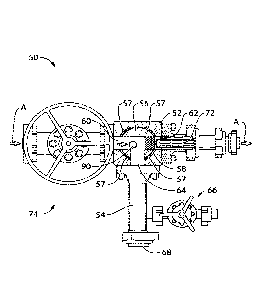
[0051] Referring now to FIG. 4, an apparatus for ball catching is shown
generally at 50. It is
to be understood that the apparatus 50 is purely exemplary, and that
variations are contemplated.
The apparatus 50 includes a body 52, a chamber 54, a rotatable plug 56, and a
screen 58 within
the rotatable plug 56.
[0052] In the present embodiment, the body 52 includes an inlet 60 for
receiving fluid
flow A and at least one frac ball 90 carried by the fluid. It is to be
appreciated that the fluid flow
A is not particularly limited and can be a liquid or gas and can contain
solids, such as debris or
proppant. The body 52 also includes a fluid outlet 62 for permitting fluid to
exit body 52. In the
present embodiment, the frac ball 90 is separated from the fluid that exits
body 52, and the fluid
that exits body 52 is generally delivered to testers or any other piece of
downstream equipment.
The body 52 further includes a ball-collection outlet 64 for accommodating the
frac ball 90 that,
for example, has been separated from fluid that exits body 52.
9
CA 02914430 2015-12-09
[0053] The chamber 54 is in fluid communication with the ball-collection
outlet 64. In the
present embodiment, the chamber 54 is connected to the ball-collection outlet
64 with a flange.
In the present embodiment, the chamber 54 is configured to receive the frac
ball 90 via the ball-
collection outlet 64. The chamber 54 can be constructed of any material or
from any design that
can provide sufficient mechanical properties to sustain the pressure. In the
present embodiment,
the chamber 54 also includes a drain valve 66 generally configured to relieve
pressure within the
chamber 54. The chamber further includes a cleanout port 68 generally
configured to allow for
removal of the frac ball 90 from the chamber 54.
[0054] The rotatable plug 56 is disposed within the body 52. In the present
embodiment, the
rotatable plug 56 has three channels in fluid communication with each other
forming a "T"
connection. Each of the channels is generally configured to align with each of
the inlet 60, the
fluid outlet 62, and the ball-collection outlet 64. In the present embodiment,
the body 52 and the
rotatable plug 56 form a three-way plug valve where the rotatable plug 56 can
freely rotate
within the body 52, which can be guided, for example, by a plurality of valve
seats 57. It is to be
appreciated that the rotatable plug 56 is not particularly limited and that
variations are
contemplated. For example, the rotatable plug 56 can include more or less than
three channels,
and the channels need not be at 90 degrees with respect with each other.
[0055] Screen 58 is disposed within one of the three channels and generally
configured to
prevent the passage of the frac ball 90 while allowing fluid to flow through
screen 58. The
screen 58 can be integral with the rotatable plug 56 (i.e. non-removable, such
as welded) to
increase the rigidity of the rotatable plug 56, or it can be removably
attached to the channel for
easy replacement and access for servicing. In addition, it is to be
appreciated that the screen 58
can be inserted into other portions of the rotatable plug 56 or the body 52.
In addition, any other
CA 02914430 2015-12-09
part or blockage can be used to prevent the passage of frac ball 90 while
allowing the passage of
fluid.
100561 The screen 58 can encourage frac ball 90 toward the ball-collection
outlet 64. For
example, in the position illustrated in FIG. 4, the apparatus 50 is configured
to receive the frac
ball 90 along with fluid via the inlet 60 such that the fluid passes through
the apparatus via the
fluid outlet 62 and screen 58 encourages the frac ball 90 to enter the chamber
54 via the ball-
collection outlet 64. Accordingly, apparatus 50 operates to separate the frac
ball 90 from the
fluid exiting outlet 62 when the rotatable plug 56 is in the position shown in
FIG. 4, which
permits frac ball 90 to be collected while fluid moves to downstream
equipment.
[0057] In the present embodiment, the apparatus 50 also includes an
optional diverter screen
72 to further facilitate diverting the frac ball 90 into the chamber 54. The
diverter screen extends
into the fluid outlet 62 and is generally configured to divert the frac ball
90 away from the fluid
outlet 62 and through the ball-collection outlet 64. In the present
embodiment, the diverter
screen 72 can provide additional support for the screen 58. Additionally, the
diverter screen 72
can be configured to filter some of the debris that passes through the screen
58. In addition, any
other part or blockage can be used to prevent the passage of frac ball 90
while allowing the
passage of fluid.
[0058] In the present embodiment, the apparatus 50 also optionally includes
a wing valve 74
for controlling the flow of the fluid. The wing valve is generally disposed
upstream of the body
52 and can be used to limit or stop the flow of fluid into the body 52.
[0059] Referring to FIG. 5, the apparatus 50 is illustrated with the
rotatable plug 56 in a
second position for blocking the flow through the apparatus 50. In this
position, channels of the
11
CA 02914430 2015-12-09
rotatable plug 56 are aligned with the inlet 60 and the ball-collection outlet
64. The third channel
is directed into the body 52 and effectively plugged. If valve 66 is closed,
chamber 54 does not
have an open outlet during use, and the apparatus 50 has stopped the fluid
flow through
apparatus 50. It is also to be appreciated that in this position, the screen
58 is aligned above the
chamber 54. Accordingly, the frac ball 90 is prevented from exiting body 52
into the chamber
54. In other embodiments, the wing valve 74 can be omitted and the position
shown in FIG. 5
can be used to limit flow to the downstream equipment.
[0060] Referring to FIG. 6, the apparatus 50 is illustrated with the
rotatable plug 56 in a third
position for preventing the frac ball 90 from entering the rotatable plug 56
and isolating the
chamber 54. In this position, channels of the rotatable plug 56 are aligned
with the inlet 60 and
the fluid outlet 62. The third channel is directed into the body 52 and
effectively plugged, and
the ball-collection outlet 64 is effectively plugged by rotatable plug 56,
isolating the chamber 54
from the fluid flow. It is also to be appreciated that in this position, the
screen 58 is aligned with
the inlet 60 to prevent the frac ball 90 from entering body 52. Accordingly,
the frac ball 90
would be prevented from entering body 52, while fluid is permitted to enter
inlet 60 and exit the
fluid outlet 62. Furthermore, it is to be appreciated that in this position,
since the chamber 54 is
isolated from the fluid flow, the chamber 54 can be opened at the cleanout
port 68 to remove any
balls therein without stopping the flow of fluid.
[0061] Referring to FIGS. 7 to 9, another embodiment of an apparatus for
ball catching is
shown generally at 50a. Like components of the apparatus 50a bear like
reference to their
counterparts in the apparatus 50, except followed by the suffix "a". The
apparatus 50a includes a
body 52a, a chamber 54a, a rotatable plug 56a, and a diverter screen 72a.
12
CA 02914430 2015-12-09
[0062] In the present embodiment, the body 52a includes an inlet 60a for
receiving fluid
flow A' and at least one frac ball 90 carried by the fluid. The body 52a also
includes a fluid
outlet 62a for permitting fluid to exit body 52a. In the present embodiment,
the frac ball 90 is
separated from the fluid that exits body 52a, and the fluid that exit body 52a
can be delivered to
testers or any other piece of downstream equipment. The body 52a further
includes a ball-
collection outlet 64a for accommodating the frac ball 90 that, for example,
has been separated
from fluid that exits body 52a.
[0063] The chamber 54a is in fluid communication with the ball-collection
outlet 64a. In the
present embodiment, the chamber 54a is configured to receive the frac ball 90
via the ball-
collection outlet 64a. The chamber 54a can be constructed of any material or
from any design
that can provide sufficient mechanical properties to sustain the pressure. In
the present
embodiment, the chamber Ma also includes a drain valve 66a generally
configured to relieve
pressure within the chamber 54a. The chamber further includes a cleanout port
68a generally
configured to allow for removal of the frac ball 90 from the chamber 54a.
[0064] The rotatable plug 56a is disposed within the body 52a and
configured to be rotatable
within a cavity of the body 52a. The manner by which the rotatable plug 56a is
rotated is not
particularly limited. For example, the rotatable plug 56a can be rotated using
a lever or any other
type of suitable valve handle. In other embodiments, the rotatable plug 56a
can also be
controlled with a motor capable of remote operation. In the present
embodiment, the rotatable
plug 56a is shaped as a circular segment. In the open position shown in FIG.
7, the rotatable
plug 56a is generally configured to allow fluid communication between the
inlet 60a, the fluid
outlet 62a, and the ball-collection outlet 64a. When in the open position, the
rotatable plug 56a
is positioned within a top portion of the cavity of the body 52a to allow
fluid to enter the cavity
13
CA 02914430 2015-12-09
from the inlet 60a and exit the body 52a via the fluid outlet 62a or the ball-
collection outlet 64a.
During operation, the chamber 54a is in fluid communication with the ball-
collection outlet 64a.
With drain valve 66a closed, pressure buildup in the chamber 54a would
eventually limit further
fluid flow through the ball-collection outlet 64a resulting in fluid flowing
from the inlet 60a,
through body 52a, and out of the fluid outlet 62a. In the present embodiment,
the range of
motion of the rotatable plug 56a is not particularly limited. For example, the
rotatable plug 56a
can freely rotate within the cavity of the body 52a guided by, for example, a
plurality of valve
seats 57a. In other embodiments, the range of motion of the rotatable plug 56a
can be limited to,
for example, 180 degrees from the position illustrated in FIG. 7 to the
position illustrated in
FIG. 9.
[00651 The
diverter screen 72a is disposed within the fluid outlet 62a and is generally
configured to divert the frac ball 90 away from the fluid outlet 62a and
through the ball-
collection outlet 64a while allowing fluid and at least some debris to flow
through the fluid outlet
62a. In the present embodiment, the diverter screen 72a is welded onto the
sidewall of the outlet
62a using a weld joint 76a. However, the diverter screen 72a is not
particularly limited and can
be varied. For example, the diverter screen 72a can be removable from the
fluid outlet 62a to
facilitate replacement or servicing. In one application, the apparatus 50a is
configured to
accommodate a frac ball 90 having a diameter of at least about 7/8 inches.
Accordingly, as
another example of a variation, the size of the diverter screen 72a can be
modified to be larger or
smaller for other applications, such as those in which a frac ball 90 has a
larger or smaller
diameter. In addition, any other part or blockage can be used to prevent the
passage of frac ball
90 while allowing the passage of fluid.
14
CA 02914430 2015-12-09
[0066] In the present embodiment, the apparatus 50a also includes a wing
valve 74a for
controlling the flow of the fluid. The wing valve is generally disposed
upstream of the body 52a
and can be used to limit or stop the flow of fluid into the body 52a.
[0067] Referring to FIG. 8, the apparatus 50a is illustrated with the
rotatable plug 56a in a
second position for preventing flow through the apparatus 50a. In this
position, the rotatable
plug 56a is aligned to prevent fluid from entering the fluid outlet 62a,
stopping the fluid flow to,
for example, downstream equipment. In some embodiments, the wing valve 74a can
be omitted
and the position shown in FIG. 8 can be used to limit flow to the downstream
equipment.
[0068] Referring to FIG. 9, the apparatus 50a is illustrated with the
rotatable plug 56a in a
third position for preventing the frac ball 90 from flowing downstream and for
preventing fluid
and frac ball 90 from entering the chamber 54a while allowing fluid to flow
from the inlet 60a to
the fluid outlet 62a. In this position, the rotatable plug 56a is aligned with
ball-collection outlet
64a to effectively isolate the chamber 54a from the fluid flow. In this
position, the diverter
screen 72a continues to prevent the frac ball 90 from passing through the
fluid outlet 62a.
Furthermore, since the chamber 54a is isolated from the fluid flow, the
chamber 54a can be
opened at the cleanout port 68a to, for example, remove any balls in chamber
54a without
stopping the flow of fluid through body 52a.
[0069] Referring to FIGS. 10a and 10b, the diverter screen 72a is shown in
greater detail. It is
to be understood that the diverter screen 72a is purely exemplary, and a
variety of diverter
screens are contemplated for the present embodiment as well as other
embodiments. The
diverter screen 72a includes a face 100a, a side 105a, and a base 110a. In the
present
embodiment, the diverter screen 72a is a unitary body; however, it is to be
appreciated that
CA 02914430 2015-12-09
=
variations are contemplated. For example, the diverter screen 72a can be
constructed from
separate pieces that are welded or otherwise attached together.
100701 The face 100a is generally configured to allow fluid and at least some
debris to pass
through face 100a. In the present embodiment, the face 100a includes a
plurality of circular
holes 115a dimensioned to prevent the ball 90 as well as larger pieces of
debris from passing
through face 100a. It is to be understood that the face 100a is not
particularly limited to any
material and that several different types of materials are contemplated. In
the present
embodiment, the face 100a is a steel plate of sufficient thickness to stop the
ball 90 in the fluid
flow. The minimum thickness of face 100a can depend, for example, on the
material of the face
100a.
100711 The side 105a is generally configured to allow fluid and at least some
debris to continue
along the fluid path and to support the face 100a within the outlet 62a. In
the present
embodiment, the side 105a includes a plurality of slots 120a dimensioned to
allow fluid and
small debris to pass through slots 120a. In particular, each slot 120a extends
almost the length of
the side 105a from the face 100a to the base 110a. It is to be understood that
the side 105a is not
particularly limited to any material, and that several different types of
materials are
contemplated. In the present embodiment, the side 105a is made from steel. In
other
embodiments, side 105a can be replaced or supplemented by a plurality of
support rods for
supporting the face 100a while allowing fluid and debris to pass between
adjacent rods. In the
present embodiment, the side 105a is configured to allow substantially all
debris to pass through
via the slot 120a so that debris does not build up in the annular chamber
formed between the
diverter screen 72a and the sidewall of the outlet 62a. However, some further
embodiments can
16
CA 02914430 2015-12-09
be configured to prevent larger debris from passing through the side 105a of
the diverter screen
72a.
[0072] The base 110a is generally configured to support the diverter screen
72a within the
outlet 62a. In particular, the base 110a is configured to be welded to the
sidewall of the outlet
62a using a weld joint 76a. It is to be understood that the base 110a is not
particularly limited to
any material and that several different types of materials are contemplated.
In the present
embodiment, the base 110a is an annular steel ring.
[0073] The manner by which the diverter screen 72a is welded into the outlet
62a of the body
52a is not particularly limited. To encourage ball 90 to enter outlet 64a, for
example, face 100a
can be positioned substantially close to an end of the outlet 62a in the
present embodiment.
[0074] Referring to FIGS. 11 to 13, another embodiment of an apparatus for
ball catching is
shown generally at 50b. Like components of the apparatus 50b bear like
reference to their
counterparts in the apparatus 50, except followed by the suffix "b". The
apparatus 50b includes
a body 52b, a chamber 54b, a rotatable plug 56b, and a screen 58b within the
rotatable plug 56b.
[0075] In the present embodiment, the body 52b includes an inlet 60b for
receiving fluid
flow A" and at least one frac ball 90 carried by the fluid. The body 52b also
includes a fluid
outlet 62b for permitting fluid to exit body 52b. In the present embodiment,
the frac ball 90 is
separated from the fluid that exits body 52b, and the fluid that exits body
52b is generally
delivered to testers or any other piece of downstream equipment. The body 52b
further includes
a ball-collection outlet 64b for accommodating the frac ball 90 that, for
example, has been
separated from fluid that exits body 52b.
17
CA 02914430 2015-12-09
[0076] The chamber 54b is in fluid communication with the ball-collection
outlet 64b. In the
present embodiment, the chamber 54b is configured to receive the frac ball 90
via the ball-
collection outlet 64b. The chamber 54b can be constructed of any material or
from any design
that can provide sufficient mechanical properties to sustain the pressure. In
the present
embodiment, the chamber 54b also includes a drain valve 66b generally
configured to relieve
pressure within the chamber 54b. The chamber further includes a cleanout port
68b generally
configured to allow for removal of the frac ball 90 from the chamber 54b.
[0077] The rotatable plug 56b is disposed within the body 52b. In the
present embodiment,
the rotatable plug 56b has three channels in fluid communication with each
other forming a "T"
connection. Each of the channels is generally configured to align with each of
the inlet 60b, the
fluid outlet 62b, and the ball-collection outlet 64b. In the present
embodiment, the body 52b and
the rotatable plug 56b form a three-way plug valve where the rotatable plug
56b can freely rotate
within the body 52b guided by, for example, a plurality of valve seats 57b. It
is to be appreciated
that the rotatable plug 56b is not particularly limited and that variations
are contemplated. For
example, the rotatable plug 56b can include more or less than three channels,
and the channels
need not be at 90 degrees with respect to each other.
[0078] The screen 58b is disposed within one of the three channels of the
rotatable plug 56b
and generally configured to prevent the passage of the frac ball 90 while
allowing fluid to flow
through screen 58b. The screen 58b is not particularly limited and can be
integral with the
rotatable plug 56b (i.e. non-removable, such as welded) to increase the
rigidity of the rotatable
plug 56b, or it can be removably attached to the channel for easy replacement
and access for
servicing.
18
CA 02914430 2015-12-09
[0079] Screen 58b can be used to encourage the movement of the frac ball 90
toward the
ball-collection outlet 64b. For example, in the position illustrated in FIG.
11, the apparatus 50b
is configured to receive the frac ball 90 along with fluid via the inlet 60b
such that the fluid
passes through the apparatus via the fluid outlet 62b and the frac ball 90 is
prevented from
passing through fluid outlet 62b and encouraged toward chamber ball-collection
outlet 64b and
into the chamber 54b. In addition, any other part or blockage can be used to
prevent the passage
of frac ball 90 while allowing the passage of fluid.
[0080] In the present embodiment, the apparatus 50b also includes a wing
valve 74b for
controlling the flow of the fluid. The wing valve is generally disposed
upstream of the body 52b
and can be used to limit or stop the flow of fluid into the body 52b.
[0081] Referring to FIG. 12, the apparatus 50b is illustrated with the
rotatable plug 56b in a
second position for preventing flow through the apparatus 50b. In this
position, the channels of
the rotatable plug 56b are aligned with the inlet 60b and the ball-collection
outlet 64b. The third
channel is directed into the body 52b and effectively plugged. If drain valve
66b is closed,
chamber 54b does not have an open outlet during use, and the apparatus 50b has
stopped the
fluid flow through apparatus 50b. It is also to be appreciated that in this
position, the screen 58b
is aligned above the chamber 54b. Accordingly, the frac ball 90 would be
prevented from
exiting body 52b into the chamber 54b. In other embodiments, the wing valve
74b can be
omitted and the position shown in FIG. 12 can be used to limit flow to the
downstream
equipment.
[0082] Referring to FIG. 13, the apparatus 50b is illustrated with the
rotatable plug 56b in a
third position for preventing the frac ball 90 from entering the rotatable
plug 56b and isolating
19
CA 02914430 2015-12-09
the chamber 54b. In this position, the channels of the rotatable plug 56b are
aligned with the
inlet 60b and the fluid outlet 62b. The third channel is directed into the
body 52b and effectively
plugged, and the ball-collection outlet 64b is effectively plugged by
rotatable plug 56b, isolating
the chamber 54b from the fluid flow. It is also to be appreciated that in this
position, the screen
58b is aligned with the inlet 60b to prevent the frac ball 90 from entering
the cavity of the body
52b. Accordingly, the frac ball 90 is prevented from entering body 52b, and
fluid is permitted
from entering body 52b and to exit the fluid outlet 62b. Furthermore, it is to
be appreciated that
in this position, since the chamber 54b is isolated from the fluid flow, the
chamber 54b can be
opened at the cleanout port 68b to remove any balls therein without stopping
the flow of fluid
through body 52b.
[0083] Referring to FIG. 14, a system for hydraulic fracturing of a well is
shown at 500
including the apparatus 50. It is to be understood that the system 500 is
purely exemplary and it
will be apparent to those skilled in the art that a variety of configurations
are contemplated. For
example, as an example of a variation, the apparatus 50a or 50b can be
substituted. The system
500 further includes a frac tree 508 and downstream equipment 512. The
downstream equipment
512 can include, for example, any combination of pipes, testing devices,
storage vessels and the
like. The frac tree 508 is connected, at a wellhead end 516, to a well 517
extending through a
ground surface 518 to the underground formations from which the recovery of
oil or gas is
desired.
[0084] In the foregoing description of certain embodiments, specific
terminology has been
resorted to for the sake of clarity. However, the disclosure is not intended
to be limited to the
specific terms so selected, and it is to be understood that each specific term
includes other
technical equivalents which operate in a similar manner to accomplish a
similar technical
CA 02914430 2015-12-09
purpose. Terms such as "left" and right", "front" and "rear", "above" and
"below" and the like
are used as words of convenience to provide reference points and are not to be
construed as
limiting terms.
[0085] In this specification, the word "comprising" is to be understood in
its "open" sense,
that is, in the sense of "including", and thus not limited to its "closed"
sense, that is the sense of
"consisting only of'. A corresponding meaning is to be attributed to the
corresponding words
"comprise", "comprised" and "comprises" where they appear.
[0086] In addition, the foregoing describes only some embodiments of the
invention(s), and
alterations, modifications, additions and/or changes can be made thereto
without departing from
the scope and spirit of the disclosed embodiments, the embodiments being
illustrative and not
restrictive.
[0087] Therefore, it is to be understood that many combinations, variations
and subsets of
the embodiments and teachings herein are contemplated. As a non-limiting
example, the
apparatus 50 can be modified with the variation of the diverter screen 72a
described in relation to
the apparatus 50a. As another non-limiting example, the apparatus 50 can omit
the screen 58.
As yet another example of a substitution, the apparatus 50 of the system 500
can be substituted
with either the apparatus 50a or 50b described above.
Furthermore, invention(s) have described in connection with what are presently
considered to be
the\ most practical and preferred embodiments, it is to be understood that the
invention is not to
be limited to the disclosed embodiments, but on the contrary, is intended to
cover various
modifications and equivalent arrangements included within the spirit and scope
of the
invention(s). Also, the various embodiments described above may be implemented
in
21
CA 02914430 2015-12-09
conjunction with other embodiments, e.g., aspects of one embodiment may be
combined with
aspects of another embodiment to realize yet other embodiments. Further, each
independent
feature or component of any given assembly may constitute an additional
embodiment.
22