Note: Descriptions are shown in the official language in which they were submitted.
CA 02915192 2015-12-14
METHOD OF USING SCALE FORMATION ON A SLOTTED LINER TO REDUCE
WATER PRODUCTION
Field of the Invention
The present invention relates to hydrocarbon recovery methods, and
specifically to methods for
reducing undesired water production from zones in a hydrocarbon wellbore.
Background of the Invention
In the art of hydrocarbon production, a wellbore is conventionally drilled
downwardly from the
surface to a formation of interest, the formation housing the target
hydrocarbon. In many cases,
the wellbore will pass through a number of formations with hydrocarbon
presence, the target
formations often separated by non-productive layers which may instead produce
undesired water,
which normally is in the form of a brine. In an effort to reduce the
production of water, it is
common to run casing down the wellbore and perforate the casing at depths
aligned with the
productive layers or zones, to effectively isolate the undesirable layers or
zones.
However, even with these and other isolation techniques, it is well known that
a producing zone
may with time generate increasing percentages of water, creating what is
commonly referred to
as a high water cut zone. Production of such water not only reduces the value
of the production
operation, but because the water is in the form of brine it can have
deleterious effects on
downhole and surface equipment such as scaling and corrosion. Various methods
and techniques
have accordingly been developed in the past to address the presence of high
water cut zones, or
to engage in zonal isolation generally. For example, United States Patent
Application
Publication No. 2012/0285692 to Potapenko et al. discloses a method for
plugging a zone with a
treatment fluid comprising particulates. As a further example, United States
Patent No.
8.167,043 to Willberg et al. discloses a well treatment method comprising a
temporary plug
derived from degradable material.
- 1 -
CA 02915192 2015-12-14
In addition, within heavy oil or bitumen production operations, it is well
known to use steam-
based thermal recovery methods, in which steam or a steam-solvent mixture is
injected into a
formation of interest to mobilize the heavy hydrocarbon and produce it to
surface. However, in
cases such as steam assisted gravity drainage (SAGD) operations, the sweeping
of the reservoir
that has already been swept numerous times with steam becomes problematic, and
installation of
equipment such as inflow control devices must be considered to address the
water production
issue and redirect steam to the unworked areas of the reservoir.
While numerous methods and techniques have been developed and are commonly
deployed,
many prior art methods for isolation of high water cut zones are undesirably
complex or costly to
implement. What is needed, therefore, is a method for reducing production of
water from high
water cut zones that is simple and inexpensive to implement, while allowing
continued
production of hydrocarbon from productive regions.
Summary of the Invention
The present invention therefore seeks to provide a method for at least
partially isolating a water-
producing zone in a hydrocarbon recovery operation, comprising the use of a
slotted liner or
other perforated casing, and encouraging scale formation/deposition around the
slots or apertures
as water is produced, thus increasingly blocking the slots or apertures and
reducing water
production from the wellbore. The scale formation/deposition may continue
until the slots or
apertures are fully blocked adjacent the water-producing zone.
In a wellbore with a plurality of zones, some of which are oil-producing and
some of which are
water-producing, the scale formation/deposition will occur at the water-
producing zones while
produced oil will coat the casing and limit or reduce scale
formation/deposition at the oil-
producing zones, thus preferentially producing oil while restricting or
completely blocking the
water production from the water-producing zones.
According to a first broad aspect of the present invention, a method is
provided for reducing
undesired water production from a hydrocarbon wellbore, the method comprising
the steps of:
- 2 -
CA 02915192 2015-12-14
a. providing a casing member having an external wall and an internal wall;
b. forming at least one aperture in the casing member extending between an
inlet in the
external wall and an outlet in the internal wall, the at least one aperture
configured to
allow passage of a fluid therethrough from outside the casing member to inside
the casing
member, the at least one aperture comprising:
a first flow restriction adjacent the inlet; and
a second flow restriction adjacent the outlet;
c. positioning the casing member in the hydrocarbon wellbore;
d. producing the fluid through the at least one aperture to surface;
e. allowing a pressure drop in the fluid across the first flow restriction,
and where the fluid
is primarily water causing precipitation of a precipitate from the fluid
within the at least
one aperture; and
allowing the second flow restriction to restrict flow of the fluid and the
precipitate out of
the outlet.
The precipitate may be allowed to accumulate within the at least one aperture,
and may be
allowed to do so until the precipitate substantially blocks the outlet.
Alternatively, the precipitate
may be allowed to accrete on walls of the at least one aperture, and may be
allowed to do so until
the precipitate substantially blocks the outlet. In some exemplary
embodiments, the precipitate
may both accrete to the walls of the at least one aperture and accumulate
within the at least one
aperture.
The fluid may be a brine water and the precipitate a salt.
In some embodiments wherein the precipitate accumulates or accretes within the
at least one
aperture and substantially blocks the outlet, and the hydrocarbon wellbore is
subjected to a
steam-based thermal hydrocarbon recovery process and steam is injected through
the casing
member, the method may involve substantially blocking the outlet to allow the
steam to be
preferentially directed to other regions of the hydrocarbon wellbore.
- 3 -
CA 02915192 2015-12-14
In some embodiments the method may further comprise the step after step f. of
injecting an acid
downhole to the casing member to dissolve the precipitate within the at least
one aperture and
allow the dissolved precipitate to pass through the outlet.
In some embodiments the method may further comprise the step of injecting a
brine solution
downhole to mix with the fluid before producing the fluid through the at least
one aperture to the
surface.
In some embodiments the fluid passing through the at least one aperture is
primarily hydrocarbon
during early production and the hydrocarbon wets the at least one aperture and
avoids
accumulation or accretion of the precipitate within the at least one aperture,
and the fluid
subsequently passing through the at least one aperture is primarily water and
the precipitate
accumulates or accretes within the at least one aperture.
According to a second broad aspect of the present invention, a method is
provided for isolating a
high water cut zone in a hydrocarbon wellbore, the method comprising the steps
of:
a. providing a casing member having an external wall and an internal wall;
b. forming at least one aperture in the casing member extending between an
inlet in the
external wall and an outlet in the internal wall, the at least one aperture
configured to
allow passage of a fluid therethrough from outside the casing member to inside
the casing
member, the at least one aperture comprising:
a first flow restriction adjacent the inlet; and
a second flow restriction adjacent the outlet;
c. positioning the casing member in the hydrocarbon wellbore;
d. producing the fluid through the at least one aperture to surface;
e. allowing a pressure drop in the fluid across the first flow restriction,
and where the fluid
is primarily water causing precipitation of a precipitate from the fluid
within the at least
one aperture; and
f. allowing the second flow restriction to restrict flow of the fluid and
the precipitate out of
the outlet.
- 4 -
CA 02915192 2015-12-14
The precipitate may be allowed to accumulate within the at least one aperture,
and may be
allowed to do so until the precipitate substantially blocks the outlet.
Alternatively, the precipitate
may be allowed to accrete on walls of the at least one aperture, and may be
allowed to do so until
the precipitate substantially blocks the outlet. In some exemplary
embodiments, the precipitate
may both accrete to the walls of the at least one aperture and accumulate
within the at least one
aperture.
The fluid may be a brine water and the precipitate a salt.
In some embodiments wherein the precipitate accumulates or accretes within the
at least one
aperture and substantially blocks the outlet, and the hydrocarbon wellbore is
subjected to a
steam-based thermal hydrocarbon recovery process and steam is injected through
the casing
member, the method may involve substantially blocking the outlet to allow the
steam to be
preferentially directed to other regions of the hydrocarbon wellbore.
In some embodiments the method may further comprise the step after step f. of
injecting an acid
downhole to the casing member to dissolve the precipitate within the at least
one aperture and
allow the dissolved precipitate to pass through the outlet.
In some embodiments the method may further comprise the step of injecting a
brine solution
downhole to mix with the fluid before producing the fluid through the at least
one aperture to the
surface.
In some embodiments the fluid passing through the at least one aperture is
primarily hydrocarbon
during early production and the hydrocarbon wets the at least one aperture and
avoids
accumulation or accretion of the precipitate within the at least one aperture,
and the fluid
subsequently passing through the at least one aperture is primarily water and
the precipitate
accumulates or accretes within the at least one aperture.
- 5 -
CA 02915192 2015-12-14
According to a third broad aspect of the present invention, a casing member is
provided for use
in reducing undesired water production from a hydrocarbon wellbore, the casing
member
comprising:
an external wall and an internal wall; and
at least one aperture in the casing member extending between an inlet in the
external wall and an
outlet in the internal wall;
wherein the at least one aperture is configured to allow passage of a fluid
therethro ugh from
outside the casing member to inside the casing member; and
wherein the at least one aperture comprises a first flow restriction adjacent
the inlet and
a second flow restriction adjacent the outlet.
The at least one aperture is preferably but not necessarily a plurality of
apertures.
The at least one aperture may comprise generally concave walls between the
first flow restriction
and the second flow restriction. Alternatively, the at least one aperture may
comprise generally
straight walls between the first flow restriction and the second flow
restriction.
The first flow restriction is preferably configured to cause precipitation of
a precipitate from the
fluid due to pressure drop of the fluid across the first flow restriction, and
the second flow
restriction is preferably configured to retain at least a portion of the
precipitate within the at least
one aperture.
In some exemplary embodiments, the first flow restriction is a narrowing of
the inlet.
In some exemplary embodiments, the second flow restriction is a narrowing of
the outlet.
A detailed description of exemplary embodiments of the present invention is
given in the
following. It is to be understood, however, that the invention is not to be
construed as being
limited to these embodiments.
- 6 -
CA 02915192 2015-12-14
Brief Description of the Drawings
In the accompanying drawings, which illustrate exemplary embodiments of the
present
invention:
Figure la is a side elevation view of prior art slotted liners with various
slot
arrangements;
Figure lb is a detailed cross-sectional view of straight and keystone slots in
prior art
slotted liners;
Figure 2a is a partial cross-sectional view of a first exemplary embodiment of
the present
invention;
Figure 2b is a detail view of an aperture as illustrated in Figure 2a; and
Figure 3 is a detail view of an aperture according to a second exemplary
embodiment of
the present invention.
Exemplary embodiments of the present invention will now be described with
reference to the
accompanying drawings.
Detailed Description of Exemplary Embodiments
Throughout the following description specific details are set forth in order
to provide a more
thorough understanding to persons skilled in the art. However, well known
elements may not
have been shown or described in detail to avoid unnecessarily obscuring the
disclosure. The
following description of examples of the invention is not intended to be
exhaustive or to limit the
invention to the precise forms of any exemplary embodiment. Accordingly, the
description and
drawings are to be regarded in an illustrative, rather than a restrictive,
sense.
- 7 -
CA 02915192 2015-12-14
The present invention is directed to methods and tools that will reduce fluid
entry or seal off the
wellbore altogether from the reservoir at certain water-producing zones as the
localized water cut
increases at those zones, thus reducing water production.
It has been noticed by the inventors that zones producing at high water cuts
tend to deposit salt
and other precipitates such as carbonates on the casing as formation water
passes through the
wellbore and expands due to pressure drop into vapour. This phenomenon is
likely occurring
throughout the wellbore, but in regions where the oil phase is sufficient to
oil-wet the steel of the
casing, it is believed that the precipitates are present but are not able to
deposit on the casing
wall.
Scale formation/deposition is widely viewed in the art as deleterious to
hydrocarbon production,
for example as a major cause of downhole screen plugging where slotted liners
are used to block
sand from entering the wellbore. Much effort has thus been expended to find
ways to counter
scale formation/deposition. See, for example, Emo et al., "Carbonate scale
formation in
thermally stimulated heavy-oil wells near Lloydminster, Saskatchewan" (Society
of Petroleum
Engineers Paper No. SPE 21548).
In the present invention, counter-intuitively for someone knowledgeable in the
art, slots or
apertures are used precisely to cause the scale formation/deposition that is
widely viewed in the
art as a problem to be countered. Instead of seeking to prevent plugging, the
present invention
instead deliberately allows and even encourages the plugging with appropriate
slot or aperture
design.
The design of the slots in a slotted liner, for example, may be modified to
encourage this
deposition so that the salt or carbonate buildup is increased and strengthened
and is able to resist
water flow into the casing from the adjacent formation. While it is believed
that oil production
through the slots will normally keep the slots clear of such build-up, slots
according to the
present invention can encourage so-called "scale off' as the water cut
increases, thereby reducing
the flow of water into the wellbore and allowing the operator to
preferentially produce the zones
- 8 -
CA 02915192 2015-12-14
along the wellbore that are generating a higher percentage of oil and thus not
experiencing scale-
off, thereby improving the economics of the well.
As was mentioned above, high water cut zones can also become increasingly
problematic in
bitumen production operations after repeated steam-based thermal recovery
cycles. Use of an
embodiment of the present invention to seal off the parts of the production
well that have a high
water cut could potentially lessen the retreatment of swept zones and maximize
the production of
oil from the reservoir.
In the present invention, two flow restrictions are deliberately introduced
into the slot or aperture
design. A first flow restriction at the slot or aperture inlet is intended to
cause a pressure drop
that triggers precipitation of precipitates such as salt or carbonate out of
the water flowing
through the slot or aperture. These precipitates are then intended to be
retained or accreted
within the slot or aperture due to the presence of a second flow restriction
adjacent the slot or
aperture outlet. Again, if oil is being produced some precipitates would
likely be present but the
natural wetting of the slot or aperture by the produced oil would allow the
precipitates to flow
through the slot or aperture. As the water percentage of the production fluid
increases, however,
the oil-wetting would decrease to the point where precipitates (which would
also increase due to
the increased water percentage) could accumulate or even accrete on the slot
or aperture walls.
In this way, the slot or aperture could increasingly seal off and reduce or
eliminate water
production from this high water cut zone. Other zones along the wellbore that
are still producing
oil, in contrast, would not plug off and would allow production from those
zones to continue.
It is well known in the art to employ casing sections such as slotted liners
to prevent at least
some of the sand in the wellbore from entering the production equipment.
Figure 1 a illustrates
some prior art slotted liner sections, with three different slot arrangements.
The first design I a is
commonly referred to as a "line slot" arrangement where the slots 2 are
arranged in a side-by-
side manner, while the second design lb is a "staggered slot" arrangement. The
third design I c
illustrates a multiple staggered slot design. Many other slot arrangements are
known in the art.
- 9 -
CA 02915192 2015-12-14
Figure lb illustrates two common prior art slot cross-sections. In the upper
image, a straight slot
design 3a is shown, which is the most common slot cross-section, the slots 4a
having a generally
continuous width from the slot inlet on the casing external wall 5a to the
slot outlet on the casing
internal wall 6a. In contrast, the lower image shows a so-called "keystone"
slot design 3b, where
the inlet in the external wall 5b of the slot 4b is narrowed but the outlet in
the internal wall 6b is
wider to prevent sand bridging within the aperture 4b, allowing sand that
enters the aperture 4b
to easily exit into the casing interior. The focus and purpose of such prior
art slotted liners is to
reduce sand production and prevent plugging of the slotted liner with sand.
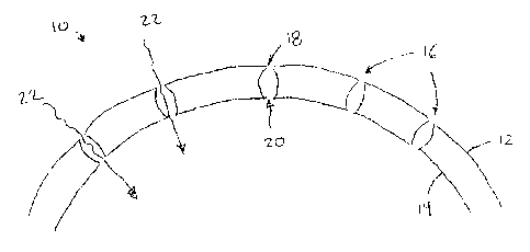
Turning now to Figures 2a and 2b, a first exemplary embodiment of the present
invention is
illustrated. In Figure 2a, a portion of a casing member 10 is shown in cross
section, which could
be a slotted liner but with modified slots as described herein, and the casing
member 10 may be
used as part of a production tubing string (not shown) positioned within a
hydrocarbon wellbore
(not shown). The casing member 10 is generally in the form of a hollow steel
tubular section,
comprising an external wall 12 and in internal wall 14. To allow the
production of formation
fluid ¨ specifically hydrocarbon such as oil ¨ the casing member 10 is
provided with a series of
apertures 16, which in the exemplary embodiment are shown as evenly spaced
around the
circumference of the casing member 10. The apertures 16 are configured to
allow the flow of the
target hydrocarbon through the casing member 10 and into the production
equipment for
production to surface facilities.
Each of the apertures 16 thus extends through the casing member from the
external wall 12 to the
internal wall 14, opening at an inlet 18 in the external wall 12 and an outlet
20 in the internal
wall 14. By providing this open passage through the casing member 10,
formation fluid 22 can
pass from the casing member 10 exterior into the interior for production to
surface.
However, as indicated above, while it is desired to produce a hydrocarbon such
as oil, it is
desired to restrict the production where the formation fluid is water, which
is commonly a brine
that can have a deleterious impact on production/processing equipment but also
impair the
economics of the production operation generally in terms of the produced fluid
value. As can
- 10 -
CA 02915192 2015-12-14
best be seen in Figure 2b, the first embodiment of the present invention
addresses this goal by
providing apertures 16 having a novel structure.
The aperture 16 according to the first illustrated embodiment comprises a
narrowing at the inlet
18, which is the first flow restriction 26. As stated above, fluid 22 passing
from the outside of
the casing member 10 into the aperture 16 will experience a pressure drop due
to flowing past
the first flow restriction 26 and into the wider aperture 16 interior. Due to
the pressure drop,
precipitation of a precipitate such as salt or carbonate is encouraged.
Rather than allowing this precipitate to freely flow out of the aperture 16,
however, the aperture
16 also comprises a second flow restriction 28 adjacent the outlet 20. The
second flow
restriction 28 in this embodiment is also a narrowing of the aperture 16, but
at the opposite, inner
end. The second flow restriction 28 provides a physical barrier in the flow
path and limits the
ability of the precipitate to exit the aperture 16 once formed.
As the precipitate forms but is discouraged from exiting the aperture 16, the
precipitate may
either accumulate within the aperture 16 and increasingly block the aperture
16, or it may accrete
on the inner walls of the aperture 16. Such accretions 24 are shown in Figure
2b, and they may
also increasingly reduce the flow path and may eventually seal off the outlet
20 altogether.
While Figures 2a and 2b illustrate an aperture 16 that is more rounded, with a
concave wall
structure, other aperture designs providing first and second flow restrictions
¨ and possibly more
than two flow restrictions ¨ are possible and are intended to fall within the
scope of the present
invention. Figure 3 illustrates one such alternative aperture design with
straight flow restrictions
and inner walls. The casing member 30 shown in Figure 3 comprises external and
inner walls
32, 34, with an aperture 36 extending from an inlet 38 to an outlet 40, the
aperture 36 providing a
passage for flow of a formation fluid 42 therethrough.
Rather than having curved restrictions gradually narrowing in each direction
from a wide central
point, the aperture 36 in Figure 3 has a generally consistent width for much
of its length, except
adjacent the inlet and outlet 38, 40 where the first and second flow
restrictions 46, 48 extend
- 11 -
CA 02915192 2015-12-14
inwardly to narrow the aperture 36 at each end. The first and second flow
restrictions 46, 48
function in a similar manner to the first and second flow restrictions 26, 28
shown in Figures 2a
and 2b and described above. In addition to providing a physical flow barrier
adjacent the outlet
40, the second flow restriction 48 also can be seen to provide an enhanced and
more protected
area for accretion of the precipitate 44.
As stated above, other aperture design variants are possible within the scope
of the present
invention, and the embodiments illustrated in Figures 2a, 2b and 3 are
intended to be merely
illustrative of the general principles of the present invention.
Given the above teaching, it will now be clear that apertures and slots can be
designed to
encourage precipitate formation and accumulation/accretion of the precipitate
within the aperture
or slot to selectively block zones producing undesirable water while allowing
production of
hydrocarbon from other zones in the wellbore. It will also be possible for the
skilled person to
use casing members and methods according to the present invention to manage
production from
the well.
Although the above teaching describes production of native water such as
subsurface brine to
cause the precipitation and aperture blockage, it is also possible to
encourage this by injection
from surface of salt or a brine solution to mix with the formation fluid
before producing the fluid
through the aperture and to the surface.
In addition, in a steam-based thermal hydrocarbon recovery operation, it will
also now be clear
to the skilled person that the present invention can be used to accumulate or
accrete precipitate
within apertures in a casing member, so that if the wellbore is subsequently
used for steam
injection the blocking or partial blocking of the casing member apertures can
act to reduce steam
loss to a zone where there is a high water cut and reduced hydrocarbon
presence, thus allowing
the steam to be preferentially directed to other regions of the hydrocarbon
wellbore.
Finally, if for any reason it is determined to be desirable to open the
apertures again after they
have been partially or fully blocked by precipitate accumulation or accretion,
it may be possible
- 12 -
CA 02915192 2015-12-14
to inject an acid or other chemical downhole to dissolve the precipitate
accumulation/accretion
and allow it to flow out of the apertures.
As will be clear from the above, those skilled in the art would be readily=
able to determine
obvious variants capable of providing the described functionality, and all
such variants and
functional equivalents are intended to fall within the scope of the present
invention.
Specific examples have been described herein for purposes of illustration.
These are only
examples. The technology provided herein can be applied to contexts other than
the exemplary
contexts described above. Many
alterations, modifications, additions, omissions and
permutations are possible within the practice of this invention. This
invention includes
variations on described embodiments that would be apparent to the skilled
person, including
variations obtained by: replacing features, elements and/or acts with
equivalent features,
elements and/or acts; mixing and matching of features, elements and/or acts
from different
embodiments; combining features, elements and/or acts from embodiments as
described herein
with features, elements and/or acts of other technology; and/or omitting
combining features,
elements and/or acts from described embodiments.
The foregoing is considered as illustrative only of the principles of the
invention. The scope of
the claims should not be limited by the exemplary embodiments set forth in the
foregoing, but
should be given the broadest interpretation consistent with the specification
as a whole.
- 13 -