Note: Descriptions are shown in the official language in which they were submitted.
CA 02915437 2015-12-14
WO 2014/202770 PCT/EP2014/063058
1
Method and Apparatus for Obtaining Spectrum Coefficients for a Replacement
Frame of an Audio Signal, Audio Decoder, Audio Receiver and System for
Transmitting Audio Signals
Description
The present invention relates to the field of the transmission of coded audio
signals, more
specifically to a method and an apparatus for obtaining spectrum coefficients
for a
replacement frame of an audio signal, to an audio decoder, to an audio
receiver and to a
system for transmitting audio signals. Embodiments relate to an approach for
constructing
a spectrum for a replacement frame based on previously received frames.
In the prior art, several approaches are described dealing with a frame-loss
at an audio
receiver. For example, when a frame is lost on the receiver side of an audio
or speech
codec, simple methods for the frame-loss-concealment as described in reference
[1] may
be used, such as:
= repeating the last received frame,
= muting the lost frame, or
= sign scrambling.
Additionally, in reference [1] an advanced technique using predictors in sub-
bands is
presented. The predictor technique is then combined with sign scrambling, and
the
prediction gain is used as a sub-band wise decision criterion to determine
which method
will be used for the spectral coefficients of this sub-band.
In reference [2] a waveform signal extrapolation in the time domain is used
for a MDCT
(Modified Discrete Cosine Transform) domain codec. This kind of approach may
be good
for monophonic signals including speech.
If one frame delay is allowed, an interpolation of the surrounding frames can
be used for
the construction of the lost frame. Such an approach is described in reference
[3], where
the magnitudes of the tonal components in the lost frame with an index m are
interpolated
using the neighboring frames indexed m-1 and m+1. The side information that
defines the
MDCT coefficient signs for tonal components is transmitted in the bit-stream.
Sign
CA 02915437 2015-12-14
WO 2014/202770 PCT/EP2014/063058
2
scrambling is used for other non-tonal MDCT coefficients. The tonal components
are
determined as a predetermined fixed number of spectral coefficients with the
highest
magnitudes. This approach selects n spectral coefficients with the highest
magnitudes as
the tonal components.
1
Cm* (k) = ¨2 (Cm_i (k) +)
Cm+1 (k)
Fig. 7 shows a block diagram representing an interpolation approach without
transmitted
side information as it is for example described in reference [4]. The
interpolation approach
operates on the basis of audio frames coded in the frequency domain using MDCT
(modified discrete cosine transform). A frame interpolation block 700 receives
the MDCT
coefficients of a frame preceding the lost frame and a frame following the
lost frame, more
specifically in the approach described with regard to Fig. 7, the MDCT
coefficients
Cm_i (k) of the preceding frame and the MDCT coefficients Cm+1 (k) of the
following
frame are received at the frame interpolation block 700. The frame
interpolation block 700
generates an interpolated MDCT coefficient Cm (k) for the current frame which
has either
been lost at the receiver or cannot be processed at the receiver for other
reasons, for
example due to errors in the received data or the like. The interpolated MDCT
coefficient
Cm (k) output by the frame interpolation block 700 is applied to block 702
causing a
magnitude scaling in scale factor band and to block 704 causing a magnitude
scaling with
an index set, and the respective blocks 702 and 704 output the MDCT
coefficient Cm (k)
scaled by the factor lc(k) and ix(k), respectively. The output signal of block
702 is input
into the pseudo spectrum block 706 generating on the basis of the received
input signal
the pseudo spectrum Pm (k) that is input into the peak detection block 708 a
signal
indicating detected peaks. The signal provided by block 702 is also applied to
the random
sign change block 712 which, responsive to the peak detection signal generated
by block
708, causes a sign change of the received signal and outputs a modified MDCT
coefficient Om (k) to the spectrum composition block 710. The scaled signal
provided by
block 704 is applied to a sign correction block 714 causing, in response to
the peak
detection signal provided by block 708 a sign correction of the scaled signal
provided by
block 704 and outputting a modified MDCT coefficientem (k) to the spectrum
composition
block 710 which, on the basis of the received signals, generates the
interpolated MDCT
coefficient C (k) that is output by the spectrum composition block 710. As is
shown in
CA 02915437 2015-12-14
WO 2014/202770 PCT/EP2014/063058
3
Fig. 7, the peak detection signal provided by block 708 is also provided to
block 704
generating the scaled MDCT coefficient.
Fig. 7 generates at the output of the block 714 the spectral coefficients Cm
(k) for the lost
frame associated with tonal components, and at the output of the block 712 the
spectral
coefficients Cm (k) for non-tonal components are provided so that at the
spectrum
composition block 710 on the basis of the spectral coefficients received for
the tonal and
non-tonal components the spectral coefficients for the spectrum associated
with the lost
frame are provided.
The operation of the FLC (Frame Loss Concealment) technique described in the
block
diagram of Fig. 7 will now be described in further detail.
In Fig. 7, basically, four modules can be distinguished:
= a shaped-noise insertion module (including the frame interpolation 700,
the
magnitude scaling within the scale factor band 702 and the random sign change
712),
= a MDCT bin classification module (including the pseudo spectrum 706 and
the peak
detection 708),
= a tonal concealment operations module (including the magnitude scaling
within the
index set 704 and the sign correction 714), and
= the spectrum composition 710.
The approach is based on the following general formula:
Cm(k) = Cm* (k)a* (k)s* (k), 0 5_ k < M
Cm* (k) is derived by a bin-wise interpolation (see block 700 "Frame
Interpolation")
1
Cm* (k) = ¨2 (Cni_i (k) + Cni+i (k))
a*(k) is derived by an energy interpolation using the geometric mean:
= scale factor band wise for all components, (see block 702 "Magnitude
Scaling in
Scalefactor Band") and
= index sub-set wise for tonal components (see block 704 "Magnitude Scaling
within
Index Set"):
CA 02915437 2015-12-14
WO 2014/202770 PCT/EP2014/063058
4
.\1424.1Ein_i
(a*)2(k) = _____________________________________
E,n
for tonal components it can be shown that a = cos(refi), with h being the
frequency
of the tonal component.
The energies E are derived based on a pseudo power spectrum, derived by a
simple
smoothing operation:
P(k) C2 (k) + (C(k + 1) ¨ C(k ¨ 1)}2
s* (k) is set randomly to +1 for non-tonal components (see block 712 "Random
Sign
Change"), and to either +1 or ¨1 for tonal components (see block 714 "Sign
Correction").
The peak detection is performed as searching for local maxima in the pseudo
power
spectrum to detect the exact positions of the spectral peaks corresponding to
the
underlying sinusoids. It is based on the tone identification process adopted
in the MPEG-1
psychoacoustic model described in reference [5]. Out of this an index sub-set
is defined
having the bandwidth of an analysis window's main-lobe in terms of MDCT bins
and the
detected peak in its center. Those bins are treated as tone dominant MDCT bins
of a
sinusoid, and the index sub-set is treated as an individual tonal component.
The sign correction s* (k) flips either the signs of all bins of a certain
tonal component, or
none. The determination is performed using an analysis by synthesis, i.e., the
SFM is
derived for both versions and the version with the lower SFM is chosen. For
the SFM
derivation, the power spectrum is needed, which in return requires the MDST
(Modified
Discrete Sine Transform) coefficients. For keeping the complexity manageable,
only the
MOST coefficients for the tonal component are derived, using also only the
MDCT
coefficients of this tonal component.
Fig. 8 shows a block diagram of an overall FLC technique which, when compared
to the
approach of Fig. 7, is refined and which is described in reference [6]. In
Fig. 8, the MDCT
coefficients Cin_l and Cm+i of a last frame preceding the lost frame and a
first frame
following the lost frame are received at an MDCT bin classification block 800.
These
coefficients are also provided to the shape-noise insertion block 802 and to
the MDCT
estimation for a tonal components block 804. At block 804 also the output
signal provided
CA 02915437 2015-12-14
WO 2014/202770 PCT/EP2014/063058
by the classification block 800 is received as well as the MDCT coefficients
Cm_2 and
Cm+2 of the second to last frame preceding the lost frame and the second frame
following
the lost frame, respectively, are received. The block 804 generates the MDCT
coefficients
Cm of the lost frame for the tonal components, and the shape-noise insertion
block 802
5 generates the MDCT spectral coefficients for the lost frame Cm for non-
tonal components.
These coefficients are supplied to the spectrum composition block 806
generating at the
output the spectral coefficients C for the lost frame. The shape-noise
insertion block 802
operates in reply to the system IT generated by the estimation block 804.
The following modifications are of interest with respect to reference [4]:
= The pseudo power spectrum used for the peak detection is derived as
Pm(k) = C4i_1(k) + CrLi(k)
= To eliminate perceptually irrelevant or spurious peaks, the peak
detection is only
applied to a limited spectral range and only local maxima that exceed a
relative
threshold to the absolute maximum of the pseudo power spectrum are considered.
The remaining peaks are sorted in descending order of their magnitude, and a
pre-
specified number of top-ranking maxima are classified as tonal peaks.
= The approach is based on the following general formula (with a being
signed this
time):
Cm(k) = Cm* (k)a(k),0 k <M
= Cm* (k) is derived as above, but the derivation of a becomes more
advanced,
following the approach
1
Em(a) = ¨2 {Em-i(a) + Em+i(a))
Substituting Em, Em_i, and Em+1 with
Em-i(a) lcm-112 + Ism-112 = lcm-112 + K1 + (g112
Em(a) a2lcm12 = a2lcm12
+ a212
Em+i(a) lcm+112 + ism+11 2 = I Cm+11 2 + I .1- a(312
whereas
sm_i A1 cm_2 + A2cm_i + a A3cm = i +
CA 02915437 2015-12-14
WO 2014/202770 PCT/EP2014/063058
6
sm AiCm_i a/A2cm, + A3cm+1 = f2 + cg"2
Sm.4.1 a Aicn, + A2 Cm+1 A3Cm+2 = f3 cq"3
yields an expression that is quadratic in a. Hence, for the given MDCT
estimate
there exist two candidates (with opposite signs) for the multiplicative
correction
factor (Ai, A2, A3 are the transformation matrices). The selection of the
better
estimate is performed similar to what is described in reference [4].
= This advanced approach requires two frames before and after the frame
loss in
order to derive the MDST coefficients of the previous and the subsequent
frame.
A delay-less version of this approach is suggested in reference [7]:
= As a starting point, the interpolation formula Cm* (k) = (Cm_i (k) + Cm+1
(k)) is
reused, but is applied for the frame m-1, resulting in:
Cm(k) = 2C_1 (k) ¨ Cm_2(k)
= Then, the
interpolation result Cm* is replaced by the true estimation (here, the
factor 2 becomes part of the correction factor: a = 2 cos(rifi)), which leads
to
Cm(k) = aCm_i (k) ¨ Cm_2(k)
= The correction factor is determined by observing the energies of two
previous
frames. From the energy computation, the MDST coefficients of the previous
frame
are approximated as
sm_i (A1 ¨ A3)cm_2 + A2Cm-i aA3cm_i = + cro
= Then, the sinusoidal energy is computed as
Em_1(a) Cm_112 ISm-112 = Cm-i12 + ccol2
= Similarly, the sinusoidal energy for frame m-2 is computed and denoted by
Em_2,
which is independent of a.
= Employing the energy requirement
Em_1(a) = Em_2
CA 02915437 2015-12-14
WO 2014/202770 PCT/EP2014/063058
7
yields again an expression that is quadratic in a.
The selection process for the candidates computed is performed as before, but
the
decision rule accounts only the power spectrum of the previous frame.
Another delay-less frame-loss-concealment in the frequency domain is described
in
reference [8]. The teachings of reference [8] can be simplified, without loss
of generality,
as:
= Prediction using a DFT of a time signal:
(a) Obtain the DFT spectrum from the decoded time domain signal that
corresponds to the received coded frequency domain coefficients Cm.
(b) Modulate the DFT magnitudes, assuming a linear phase change, to predict
the
missing frequency domain coefficients in the next frame Cm+1
= Prediction using a magnitude estimation from the received frequency
spectra:
(a) Find Cm and Sm' , using Cm as input, such that
(k) = Qm(k) cos(cp,(k) +
S( k) = Qm(k) sin((pm(k) + x)
where Qm(k) is the magnitude of the DFT coefficient that corresponds to
Cm (k).
(b) Calculate:
Qm(k) = ICTIV1c)12 +
Cm(k)
(Pm(') = arccos Qm(k)
(c) Perform a linear extrapolation of the magnitude and the phase:
Qm+i(k) = 2Qm(k) Qm.--1(k)
in+i(k) = 2(13m(k) com-i(k)
Cm+i(k) = Qm+i(k) cos(pm+i(k))
= Use filters to calculate Cm' and Sm' from Cm and then proceed as above to
get
Cm+i(k)
= Use an adaptive filter to calculate Cm+i(k):
CA 02915437 2015-12-14
WO 2014/202770 PCT/EP2014/063058
8
Cm+i(k) = (k) + Cm_t(k)
t=o
The selection of spectrum coefficients to be predicted is mentioned in
reference [8] but is
not described in detail.
In reference [9] it has been recognized that, for quasi-stationary signals,
the phase
difference between successive frames is almost constant and depends only on
the
fractional frequency. However, only a linear extrapolation from the last two
complex
spectra is used.
In AMR-WB+ (see reference [10]) a method described in reference [11] is used.
The
method in reference [11] is an extension of the method described in reference
[8] in a
sense that it uses also the available spectral coefficients of the current
frame, assuming
that only a part of the current frame is lost. However, the situation of a
complete loss of a
frame is not considered in reference [11].
Another delay-less frame-loss-concealment in the MDCT domain is described in
reference
[12]. In reference [12] it is first determined if the lost Pth frame is a
multiple-harmonic
frame. The lost Pth frame is a multiple-harmonic frame if more than Ko frames
among K
frames before the Pth frame have a spectrum flatness smaller than a threshold
value. If the
lost Pth frame is a multiple-harmonic frame then (P - K)t, to (P - 2),d frames
in the MDCT-
MDST domain are used to predict the lost Pth frame. A spectral coefficient is
a peak if its
power spectrum is bigger than the two adjacent power spectrum coefficients. A
pseudo
spectrum as described in reference [13] is used for the (P - 1)st frame.
A set of spectral coefficients S, is constructed from L1 power spectrum frames
as follows:
Obtaining L1 sets St,
, Su composed of peaks in each of L1 frames, a number of peaks
in each set being Nt, , Nu respectively. Selecting a set S, from the L1
sets of S1, , SL1.
For each peak coefficient mi, j = 1...N; in the set St, judging whether there
is any
frequency coefficient among mj, mj.ft , , mj+k belonging to all other peak
sets. If there is
any, putting all the frequencies mj,
, mii.k into the frequency set Sc. If there is no
frequency coefficient belonging to all other peak sets, directly putting all
the frequency
coefficients in a frame into the frequency set Sc. Said k is a nonnegative
integer. For all
spectral coefficients in the set Sc the phase is predicted using L2 frames
among (P - K)th
CA 02915437 2016-11-28
$ =
9
=
to (P - MDCT-MDST frames. The prediction is done using a linear
extrapolation (when
L2=2) or a linear fit (when L2>2). For the linear extrapolation:
'Srtin)= iroti (in) P __ Wi t1 - t2 (in) - WO]
where p, t1 and t2 are frame indices.
The spectral coefficients not in the set Sc are obtained using a plurality of
frames before the
(P - 1)st frame, without specifically explaining how.
It is an object of the present invention to provide an improved approach for
obtaining
spectrum coefficients for a replacement frame of an audio signal.
The present invention provides a method for obtaining spectrum coefficients
for a
replacement frame of an audio signal, the method comprising:
detecting a tonal component of a spectrum of an audio signal based on a peak
that exists in
the spectra of frames preceding a replacement frame;
for the tonal component of the spectrum, predicting spectrum coefficients for
the peak and its
surrounding in the spectrum of the replacement frame; and
for the non-tonal component of the spectrum, using a non-predicted spectrum
coefficient for
the replacement frame or a corresponding spectrum coefficient of a frame
preceding the
replacement frame.
The present invention provides an apparatus for obtaining spectrum
coefficients for a
replacement frame of an audio signal, the apparatus comprising:
CA 02915437 2015-12-14
WO 2014/202770 PCT/EP2014/063058
a detector configured to detect a tonal component of a spectrum of an audio
signal based
on a peak that exists in the spectra of frames preceding a replacement frame;
and
a predictor configured to predict for the tonal component of the spectrum the
spectrum
5 coefficients for the peak and its surrounding in the spectrum of the
replacement frame;
wherein for the non-tonal component of the spectrum a non-predicted spectrum
coefficient
for the replacement frame or a corresponding spectrum coefficient of a frame
preceding
the replacement frame is used.
The present invention provides an apparatus for obtaining spectrum
coefficients for a
replacement frame of an audio signal, the apparatus being configured to
operate
according to the inventive method for obtaining spectrum coefficients for a
replacement
frame of an audio signal.
The present invention provides an audio decoder, comprising the inventive an
apparatus
for obtaining spectrum coefficients for a replacement frame of an audio
signal.
The present invention provides an audio receiver, comprising the inventive
audio decoder.
The present invention provides a system for transmitting audio signals, the
system
comprising:
an encoder configured to generate coded audio signal; and
the inventive decoder configured to receive the coded audio signal, and to
decode the
coded audio signal.
The present invention provides a non-transitory computer program product
comprising a
computer readable medium storing instructions which, when executed on a
computer,
carry out the inventive method for obtaining spectrum coefficients for a
replacement frame
of an audio signal.
The inventive approach is advantageous as it provides for a good frame-loss
concealment
of tonal signals with a good quality and without introducing any additional
delay. The
inventive low delay codec is advantageous as it performs well on both speech
and audio
CA 02915437 2015-12-14
WO 2014/202770 PCT/EP2014/063058
11
signals and benefits, for example in an error prone environment, from the good
frame-loss
concealment that is achieved especially for stationary tonal signals. A delay-
less frame-
loss-concealment of monophonic and polyphonic signals is proposed, which
delivers good
results for tonal signals without degradation of the non-tonal signals.
In accordance with embodiments of the present invention, an improved
concealment of
tonal components in the MDCT domain is provided. Embodiments relate to audio
and
speech coding that incorporate a frequency domain codec or a switched
speech/frequency domain codec, in particular to a frame-loss concealment in
the MDCT
(Modified Discrete Cosine Transform) domain. The invention, in accordance with
embodiments, proposes a delay-less method for constructing an MDCT spectrum
for a
lost frame based on the previously received frames, where the last received
frame is
coded in the frequency domain using the MDCT.
In accordance with preferred embodiments, the inventive approach includes the
detection
of the parts of the spectrum which are tonal, for example using the second to
last complex
spectrum to get the correct location or place of the peak, using the last real
spectrum to
refine the decision if a bin is tonal, and using pitch information for a
better detection either
of a tone onset or offset, wherein the pitch information is either already
existing in the bit-
stream or is derived at the decoder side. Further, the inventive approach
includes a
provision of a signal adaptive width of a harmonic to be concealed. The
calculation of the
phase shift or phase difference between frames of each spectral coefficient
that is part of
a harmonic is also provided, wherein this calculation is based on the last
available
spectrum, for example the CMDCT spectrum, without the need for the second to
last
CMDCT. In accordance with embodiments, the phase difference is refined using
the last
received MDCT spectrum, and the refinement may be adaptive, dependent on the
number
of consecutively lost frames. The CMDCT spectrum may be constructed from the
decoded
time domain signal which is advantageous as it avoids the need for any
alignment with the
codec framing, and it allows for the construction of the complex spectrum to
be as close
as possible to the lost frame by exploiting the properties of low-overlap
windows.
Embodiments of the invention provide a per frame decision to use either time
domain or
frequency domain concealment.
The inventive approach is advantageous, as it operates fully on the basis of
information
already available at the receiver side when determining that a frame has been
lost or
needs to be replaced and there is no need for additional side information that
needs to be
CA 02915437 2015-12-14
WO 2014/202770 PCT/EP2014/063058
12
received so that there is also no source for additional delays which occur in
prior art
approaches given the necessity to either receive the additional side
information or to
derive the additional side information from the existing information at hand.
The inventive approach is advantageous when compared to the above described
prior art
approaches as the subsequently outlined drawbacks of such approaches, which
were
recognized by the inventors of the present invention, are avoided when
applying the
inventive approach.
The methods for the frame-loss-concealment described in reference [1] are not
robust
enough and don't produce good enough results for tonal signals.
The waveform signal extrapolation in time domain, as described in reference
[2], cannot
handle polyphonic signals and requires an increased complexity for concealment
of very
stationary, tonal signals, as a precise pitch lag must be determined.
In reference [3] an additional delay is introduced and significant side
information is
required. The tonal component selection is very simple and will choose many
peaks
among non-tonal components.
The method described in reference [4] requires a look-ahead on the decoder
side and
hence introduces an additional delay of one frame. Using the smoothed pseudo
power
spectrum for the peak detection reduces the precision of the location of the
peaks. It also
reduces the reliability of the detection since it will detect peaks from noise
that appear in
just one frame.
The method described in reference [6] requires a look-ahead on the decoder
side and
hence introduces an additional delay of two frames. The tonal component
selection
doesn't check for tonal components in two frames separately, but relies on an
averaged
spectrum, and thus it will have either too many false positives or false
negatives making it
impossible to tune the peak detection thresholds. The location of the peaks
will not be
precise because the pseudo power spectrum is used. The limited spectral range
for peak
search looks like a workaround for the described problems that arises because
pseudo
power spectrum is used.
CA 02915437 2015-12-14
WO 2014/202770 PCT/EP2014/063058
13
The method described in reference [7] is based on the method described in
reference [6]
and hence has the same drawbacks; it just overcomes the additional delay.
In reference [8] there is no detailed description of the decision whether a
spectral
coefficient belongs to the tonal part of the signal. However, the synergy
between the tonal
spectral coefficients detection and the concealment is important and thus a
good detection
of tonal components is important. Further, it has not been recognized to use
filters
dependent on both Cm and Cm_i (that is Cm, Cm_i and Sm_l, as Sm_i can be
calculated
when Cm, and Cm_i is available) to calculate Cm and S. . Also, it was not
recognized to
use the possibility to calculate a complex spectrum that is not aligned to the
coded signal
framing, which is given with low overlap windows. In addition, it was not
recognized to use
the possibility to calculate the phase difference between frames only based on
the second
last complex spectrum.
In reference [12] at least three previous frames must be stored in memory,
thereby
significantly increasing the memory requirements. The decision whether to use
tonal
concealment may be wrong and a frame with one or more harmonics may be
classified as
a frame without multiple harmonics. The last received MDCT frame is not
directly used to
improve the prediction of the lost MDCT spectrum, but just in the search for
the tonal
components. The number of MDCT coefficients to be concealed for a harmonic is
fixed,
however, depending on the noise level, it is desirable to have a variable
number of MDCT
coefficients that constitute one harmonic.
In the following, embodiments of the present invention will be described in
further detail
with reference to the accompanying drawings, in which:
Fig. 1 shows a simplified block diagram of a system for transmitting
audio signals
implementing the inventive approach at the decoder side,
Fig. 2 shows a flow diagram of the inventive approach in accordance with an
embodiment,
Fig. 3 is a schematic representation of the overlapping MDCT windows
for
neighboring frames,
Fig. 4 shows a flow diagram representing the steps for picking a peak
in accordance
with an embodiment,
CA 02915437 2015-12-14
WO 2014/202770 PCT/EP2014/063058
14
Fig. 5 is a schematic representation of a power spectrum of a frame
from which one
or more peaks are detected,
Fig. 6 shows an example for a "frame in-between",
Fig. 7 shows a block diagram representing an interpolation approach
without
transmitted side information, and
Fig. 8 shows a block diagram of an overall FLC technique refined when
compared to
Fig. 7.
In the following, embodiments of the inventive approach will be described in
further detail
and it is noted that in the accompanying drawings elements having the same or
similar
functionality are denoted by the same reference signs. In the following
embodiments of
the inventive approach will be described, in accordance with which a
concealment is done
in the frequency domain only if the last two received frames are coded using
the MDCT.
Details about the decision whether to use time or frequency domain concealment
on a
frame loss after receiving two MDCT frames will also be described. With regard
to the
embodiments described in the following it is noted that the requirement that
the last two
frames are coded in the frequency domain does not reduce the applicability of
the
inventive approach as in a switched codec the frequency domain will be used
for
stationary tonal signals.
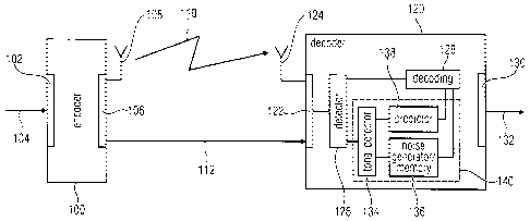
Fig. 1 shows a simplified block diagram of a system for transmitting audio
signals
implementing the inventive approach at the decoder side. The system comprises
an
encoder 100 receiving at an input 102 an audio signal 104. The encoder is
configured to
generate, on the basis of the received audio signal 104, an encoded audio
signal that is
provided at an output 106 of the encoder 100. The encoder may provide the
encoded
audio signal such that frames of the audio signal are coded using MDCT. In
accordance
with an embodiment the encoder 100 comprises an antenna 108 for allowing for a
wireless transmission of the audio signal, as is indicated at reference sign
110. In other
embodiments, the encoder may output the encoded audio signal provided at the
output
106 via a wired connection line, as it is for example indicated at reference
sign 112.
The system further comprises a decoder 120 having an input 122 at which the
encoded
audio signal provided by the encoder 106 is received. The encoder 120 may
comprise, in
accordance with an embodiment, an antenna 124 for receiving a wireless
transmission
110 from the encoder 100. In another embodiment, the input 122 may provide for
a
CA 02915437 2015-12-14
WO 2014/202770 PCT/EP2014/063058
connection to the wired transmission 112 for receiving the encoded audio
signal. The
audio signal received at the input 122 of the decoder 120 is applied to a
detector 126
which determines whether a coded frame of the received audio signal that is to
be
decoded by the decoder 120 needs to be replaced. For example, in accordance
with
5 embodiments, this may be the case when the detector 126 determines that a
frame that
should follow a previous frame is not received at the decoder or when it is
determined that
the received frame has errors which avoid decoding it at the decoder side 120.
In case it
is determined at detector 126 that a frame presented for decoding is
available, the frame
will be forwarded to the decoding block 128 where a decoding of the encoded
frame is
10 carried out so that at the output of the decoder 130 a stream of decoded
audio frames or a
decoded audio signal 132 can be output.
In case it is determined at block 126 that the frame to be currently processed
needs a
replacement, the frames preceding the current frame which needs a replacement
and
15 which may be buffered in the detector circuitry 126 are provided to a
tonal detector 134
determining whether the spectrum of the replacement includes tonal components
or not.
In case no tonal components are provided, this is indicated to the noise
generator/memory
block 136 which generates spectral coefficients which are non-predictive
coefficients
which may be generated by using a noise generator or another conventional
noise
generating method, for example sign scrambling or the like. Alternatively,
also predefined
spectrum coefficients for non-tonal components of the spectrum may be obtained
from a
memory, for example a look-up table. Alternatively, when it is determined that
the
spectrum does not include tonal components, instead of generating non-
predicted spectral
coefficients, corresponding spectral characteristics of one of the frames
preceding the
replacement may be selected.
In case the tonal detector 134 detects that the spectrum includes tonal
components, a
respective signal is indicated to the predictor 138 predicting, in accordance
with
embodiments of the present invention described later, the spectral
coefficients for the
replacement frame. The respective coefficients determined for the replacement
frame are
provided to the decoding block 128 where, on the basis of these spectral
coefficients, a
decoding of the lost or replacement frame is carried out.
As is shown in Fig. 1, the tonal detector 134, the noise generator 136 and the
predictor
138 define an apparatus 140 for obtaining spectral coefficients for a
replacement frame in
CA 02915437 2015-12-14
WO 2014/202770 PCT/EP2014/063058
16
a decoder 120. The depicted elements may be implemented using hardware and/or
software components, for example appropriately programmed processing units.
Fig. 2 shows a flow diagram of the inventive approach in accordance with an
embodiment.
In a first step S200 an encoded audio signal is received, for example at a
decoder 120 as
it is depicted in Fig. 1. The received audio signal may be in the form of
respective audio
frames which are coded using MDCT.
In step S202 it is determined whether or not a current frame to be processed
by the
decoder 120 needs to be replaced. A replacement frame may be necessary at the
decoder side, for example in case the frame cannot be processed due to an
error in the
received data or the like, or in case the frame was lost during transmission
to the
receiver/decoder 120, or in case the frame was not received in time at the
audio signal
receiver 120, for example due to a delay during transmission of the frame from
the
encoder side towards the decoder side.
In case it is determined in step S202, for example by the detector 126 in
decoder 120, that
the frame to be currently processed by the decoder 120 needs to be replaced,
the method
proceeds to step S204 at which a further determination is made whether or not
a
frequency domain concealment is required. In accordance with an embodiment, if
the
pitch information is available for the last two received frames and if the
pitch is not
changing, it is determined at step S204 that a frequency domain concealment is
desired.
Otherwise, it is determined that a time domain concealment should be applied.
In an
alternative embodiment, the pitch may be calculated on a sub-frame basis using
the
decoded signal, and again using the decision that in case the pitch is present
and in case
it is constant in the sub-frames, the frequency domain concealment is used,
otherwise the
time domain concealment is applied.
In yet another embodiment of the present invention, a detector, for example
the detector
126 in decoder 120, may be provided and may be configured in such a way that
it
additionally analyzes the spectrum of the second to last frame or the last
frame or both of
these frames preceding the replacement frame and to decide, based on the peaks
found,
whether the signal is monophonic or polyphonic. In case the signal is
polyphonic, the
frequency domain concealment is to be used, regardless of the presence of
pitch
information. Alternatively, the detector 126 in decoder 120, may be configured
in such a
way that it additionally analyzes the one or more frames preceding the
replacement frame
CA 02915437 2015-12-14
WO 2014/202770 PCT/EP2014/063058
17
so as to indicate whether a number of tonal components in the signal exceeds a
predefined threshold or not. In case the number of tonal components in the
signal
exceeds the threshold the frequency domain concealment will be used
In case it is determined in step S204 that a frequency domain concealment is
to be used,
for example by applying the above mentioned criteria, the method proceeds to
step 8206,
where a tonal part or a tonal component of a spectrum of the audio signal is
detected
based on one or more peaks that exist in the spectra of the preceding frames,
namely one
or more peaks that are present at substantially the same location in the
spectrum of the
second to last frame and the spectrum of the last frame preceding the
replacement frame.
In step 8208 it is determined whether there is a tonal part of the spectrum.
In case there is
a tonal part of the spectrum, the method proceeds to step S210, where one or
more
spectrum coefficients for the one or more peaks and their surroundings in the
spectrum of
the replacement frame are predicted, for example on the basis of information
derivable
from the preceding frames, namely the second to last frame and the last frame.
The
spectrum coefficient(s) predicted in step S210 is (are) forwarded, for example
to the
decoding block 128 shown in Fig. 1, so that, as is shown at step 212, decoding
of the
frame of the encoded audio signal on the basis of the spectrum coefficients
from step 210
can be performed.
In case it is determined in step S208 that there is no tonal part of the
spectrum, the
method proceeds to step S214, using a non-predicted spectrum coefficient for
the
replacement frame or a corresponding spectrum coefficient of a frame preceding
the
replacement frame which are provided to step 8212 for decoding the frame.
In case it is determined in step 8204 that no frequency domain concealment is
desired,
the method proceeds to step 8216 where a conventional time domain concealment
of the
frame to be replaced is performed and on the basis of the spectrum
coefficients generated
by the process in step S216 the frame of the encoded signal is decoded in step
8212.
In case it is determined at step 8202 that there is no replacement frame in
the audio
signal currently processed, i.e. the currently processed frame can be fully
decoded using
the conventional approaches, the method directly proceeds to step S212 for
decoding the
frame of the encoded audio signal.
CA 02915437 2015-12-14
WO 2014/202770 PCT/EP2014/063058
18
In the following, further details in accordance with embodiments of the
present invention
will be described.
Power spectrum calculation
For the second-last frame, indexed m ¨2, the MDST coefficients S m_2 are
calculated
directly from the decoded time domain signal.
For the last frame an estimated MDST spectrum is used which is calculated from
the
MDCT coefficients Cm..., of the last received frame (see e.g., reference
[13]):
ISm-i 0) = C,n_i (k +1)¨ Cm_i (k ¨1)I
The power spectra for the frames m ¨2 and m ¨I are calculated as follows:
Pm-2(k)=1S m-2002 + C m-2(02
P m _ l(k) =115m_i (kr IC m _ 10012
with:
Sm_i(k) MDST coefficient in frame m-1,
C,n_i(k) MDCT coefficient in frame m-1,
S5_2(k) MDST coefficient in frame m-2, and
C In-2(k) MDCT coefficient in frame m-2.
The obtained power spectra are smoothed as follows:
Psmoothe42_2(0= 0.75. Pm_2(k -0+ Pm_2(10+ 0.75. Pm_2(k +0
Psmoothecjõi(k)= 0.75. 1)(k ¨ 0 + P,1(10+ 0.75. 11(k +1)
Detection of tonal components
Peaks existing in the last two frames (m ¨2 and m ¨1) are considered as
representatives
of tonal components. The continuous existence of the peaks allows for a
distinction
between tonal components and randomly occurring peaks in noisy signals.
Pitch information
It is assumed that the pitch information is available:
. calculated on the encoder side and available in the bit-stream, or
CA 02915437 2015-12-14
WO 2014/202770 PCT/EP2014/063058
19
= calculated on the decoder side.
The pitch information is used only if all of the following conditions are met:
= the pitch gain is greater than zero
= the pitch lag is constant in the last two frames
o the fundamental frequency is greater than 100 Hz
The fundamental frequency is calculated from the pitch lag:
F ¨ 2 =FrameSize
PitchLag
If there is P"c = n= Fo for which N>5 harmonics are the strongest in the
spectrum then Fo is
set to F(,. Fo is not reliable if there are not enough strong peaks at the
positions of the
harmonics n.P.
In accordance with an embodiment, the pitch information is calculated on the
framing
aligned to the right border of the MDCT window shown in Fig. 3. This alignment
is
beneficial for the extrapolation of the tonal parts of a signal as the overlap
region 300,
being the part that requires concealment, is also used for pitch lag
calculation.
In another embodiment, the pitch information may be transferred in the bit-
stream and
used by the codec in the clean channel and thus comes at no additional cost
for the
concealment.
Envelope
In the following a procedure is described for obtaining a spectrum envelope,
which is
needed for the peak picking described later.
The envelope of each power spectrum in the last two frames is calculated using
a moving
average filter of length L:
k41,12]
Envelope(k)=-- Epo
1=k41,12]
The filter length depends on the fundamental frequency (and may be limited to
the range
[7,23]):
CA 02915437 2015-12-14
WO 2014/202770 PCT/EP2014/063058
( ( \\
L= max 7, mm 23,1+2*
2
- -J
This connection between L and Fo is similar to the procedure described in
reference [14],
however, in the present invention the pitch information from the current frame
is used that
5 includes a look-ahead, wherein reference [14] uses an average pitch
specific to a talker. If
the fundamental frequency is not available or not reliable, the filter length
L is set to 15.
Peak picking
The peaks are first searched in the power spectrum of the frame m ¨1 based on
10 predefined thresholds. Based on the location of the peaks in the frame m-
1, the
thresholds for the search in the power spectrum of the frame m-2 are adapted.
Thus the
peaks that exist in both frames (m ¨1 and m ¨2 ) are found, but the exact
location is
based on the power spectrum in the frame m-2. This order is important because
the
power spectrum in the frame m ¨1 is calculated using only an estimated MDST
and thus
15 the location of a peak is not precise. It is also important that the
MDCT of the frame m ¨1
is used, as it is unwanted to continue with tones that exist only in the frame
rn-2 and not
in the frame m ¨1. Fig. 4 shows a flow diagram representing the above steps
for picking a
peak in accordance with an embodiment. In step S400 peaks are searched in the
power
spectrum of the last frame m ¨1 preceding the replacement frame based on one
or more
20 predefined thresholds. In step S402, the one or more thresholds are
adapted. In step
S404 peaks are searched in the power spectrum of the second last frame m-2
preceding the replacement frame based on one or more adapted thresholds.
Fig. 5 is a schematic representation of a power spectrum of a frame from which
one or
more peaks are detected. In Fig. 5, the envelope 500 is shown which may be
determined
as outlined above or which may be determined by other known approaches. A
number of
peak candidates is shown which are represented by the circles in Fig. 5.
Finding, among
the peak candidate, a peak will be described below in further detail. Fig. 5
shows at a
peak 502 that was found as well as a false peak 504 and a peak 506
representing noise.
In addition, a left foot 508 and a right foot 510 of a spectral coefficient
are shown.
CA 02915437 2015-12-14
WO 2014/202770 PCT/EP2014/063058
21
In accordance with an embodiment, finding peaks in the power spectrum P of the
last
frame m ¨1 preceding the replacement frame is done using the following steps
(step
S400 in Fig. 4):
= a spectral coefficient is classified as a tonal peak candidate if all of
the following
criteria are met:
0 the ratio between the smoothed power spectrum and the envelope
500 is
greater than a certain threshold:
Psmoothedm_1(k)` > 8.8dB ,
1 O=log10
Envelope51(k)
0 the ratio between the smoothed power spectrum and the envelope
500 is
greater than its surrounding neighbors, meaning it is a local maximum,
= local maxima are determined by finding the left foot 508 and the right
foot 510 of a
spectral coefficient k and by finding a maximum between the left foot 508 and
the
right foot 510. This step is required as can be seen in Fig. 4, where the
false peak
504 may be caused by a side lobe or by quantization noise.
The thresholds for the peak search in the power spectrum P2 of the second last
frame
m ¨ 2 are set as follows (step S402 in Fig. 4):
= in the spectrum coefficients k E - 1, i +1] around a peak at an index i
in P,n_i :
Threshola(k)= (Psmoothec(n_i(k)> Envelopem_i(k))? 9.21dB:10.56 dB ,
= if Fo is available and reliable then for each n E[1, IV] set k =Ln = Foi
and
frac=n=Fo¨k:
Thresholc(k)= 8.8 dB +10.1ogio(0.35)
Thresholc(k ¨1)= 8.8 dB +10.1ogio (0.35 + 2 frac)
Thresholc(k +1) = 8.8 dB +10 =logio(0.35 + 2.(1¨frac)),
CA 02915437 2015-12-14
WO 2014/202770 PCT/EP2014/063058
22
if k e [i-1,i+1] around a peak at index i in P
then the thresholds set in the first
step are overwritten,
= for all other indices:
Threshold(k)= 20.8 dB
Tonal peaks are found in the power spectrum P of the second last frame m ¨2 by
the
following steps (step S404 in Fig. 4):
= a spectral coefficient is classified as a tonal peak if:
0
the ratio of the power spectrum and the envelope is greater than the
threshold:
(
Psmoothedõ,_2 (kr > Threshold(k) ,
10 ./ogio Envelopem_2(k) i
0 the ratio
of the power spectrum and the envelope greater than its surrounding
neighbors, meaning it is a local maximum,
= local maxima are determined by finding the left foot 508 and the right
foot 510 of a
spectral coefficient k and by finding a maximum between the left foot 508 and
the
right foot 510,
= the left foot 508 and the right foot 510 also define the surrounding of a
tonal peak
502, i.e. the spectral bins of the tonal component where the tonal concealment
method will be used.
Using the above described method, reveals that the right peak 506 in Fig. 4
only exists in
one of the frames, i.e., it does not exist in both of frames m ¨1 or rri-2.
Therefore, this
peak is marked as noise and is not selected as a tonal component.
Sinusoidal parameter extraction
(27r 1 \
For a sinusoidal signal x(t)= A = sin ¨1/ + Al)n+ 0 a shift for N/2 (the MDCT
hop size)
N 1
results in the signal
CA 02915437 2015-12-14
WO 2014/202770 PCT/EP2014/063058
23
(27c N \ ( 27r /
x(t)= A = sin ¨ + + ¨ + = A = sin V + Al)n +
71-0 + AO+ 0
Thus, there is the phase shift A(0 = 7r = (1+Al), where 1 is the index of a
peak. Hence the
phase shift depends on the fractional part of the input frequency plus an
additional adding
of rc for odd spectral coefficients.
The fractional part of the frequency Al can be derived using a method
described, e.g., in
reference [15]:
= given that the magnitude of the signal in sub-band k = 1 is a local
maximum, Al
may be determined by computing the ratio of the magnitudes of the signal in
the
sub-bands k = 1 ¨1 and k = 1 +1 , i.e., by evaluating:
1
27c
Al +
P(1-1)
\, 2
AI P(1+1) H( 27r Al ¨ ¨1)\
N \,
2)
where the approximation of the magnitude response of a window is used:
bit
(cos)1 , w < ¨
I H ("1)12b
where b is the width of the main lobe. The constant G in this expression has
been
adjusted to 27.4/20.0 in order to minimize the maximum absolute error of the
estimation,
= substituting the approximated frequency response and letting
R=1) G P (1 -1)12.G
VP(1+1) P(1+1)
_
= 2 = b
leads to:
CA 02915437 2015-12-14
WO 2014/202770 PCT/EP2014/063058
24
r
cos ¨ ¨ R = cos
b' b' j
Al = -- = arctan "
sin(-7r + R = sin( 37r
j
MDCT prediction
For all spectrum peaks found and their surroundings, the MDCT prediction is
used. For all
other spectrum coefficients sign scrambling or a similar noise generating
method may be
used.
All spectrum coefficients belonging to the found peaks and their surroundings
belong to
the set that is denoted as K. For example, in Fig. 5 the peak 502 was
identified as a peak
representing a tonal component. The surrounding of the peak 502 may be
represented by
a predefined number of neighboring spectral coefficients, for example by the
spectral
coefficients between the left foot 508 and the right foot 510 plus the
coefficients of the feet
508, 510.
In accordance with embodiments, the surrounding of the peak is defined by a
predefined
number of coefficients around the peak 502. The surrounding of the peak may
comprises
a first number of coefficients on the left from the peak 502 and a second
number of
coefficients on the right from the peak 502. The first number of coefficients
on the left from
the peak 502 and the second number of coefficients on the right from the peak
502 may
be equal or different.
In accordance with embodiments applying the EVS standard the predefined number
of
neighboring coefficients may be set or fixed in a first step, e.g. prior to
detecting the tonal
component. In the EVS standard three coefficients on the left from the peak
502, three
coefficients on the right and the peak 502 may be used, i.e., all together
seven coefficients
(this number was chosen for complexity reasons, however, any other number will
work as
well).
In accordance with embodiments, the size of the surrounding of the peak is
adaptive. The
surroundings of the peaks identified as representing a tonal component may be
modified
such that the surroundings around two peaks don't overlap. In accordance with
embodiments, a peak is always considered only with its surrounding and they
together
define a tonal component.
CA 02915437 2015-12-14
WO 2014/202770 PCT/EP2014/063058
For the prediction of the MDCT coefficients in a lost frame, the power
spectrum (the
magnitude of the complex spectrum) in the second last frame is used:
5 Qm_2 (k) = P,n_2(k) = S 02 C,72_2 Of)2 .
The lost MDCT coefficient in the replacement frame is estimated as:
Cm = Qm_2 COS(cOm (k)).
In the following a method for calculating the phase com(k) in accordance with
an
embodiment will be described.
Phase prediction
For every spectrum peak found, the fractional frequency Al is calculated as
described
above and the phase shift is:
Aco = 71" = +Al).
(0 is the phase shift between the frames. It is equal for the coefficients in
a peak and its
surrounding.
The phase for each spectrum coefficient at the peak position and the
surroundings (k E K)
is calculated in the second last received frame using the expression:
( S (k)
cool-2 (k) = arctan
The phase in the lost frame is predicted as:
c0m(10= c9m-2 (1C) 2Aco
In accordance with an embodiment, a refined phase shift may be used. Using the
calculated phase q_2(k) for each spectrum coefficient at the peak position and
the
CA 02915437 2015-12-14
WO 2014/202770 PCT/EP2014/063058
26
surroundings allows for an estimation of the MDST in the frame m ¨1 which can
be
derived as:
Sm _1(0= Qm_2(k)= sinGoni_2 00+ Aq)(k))
with:
Q2(k) power spectrum (magnitude of the complex spectrum) in frame m-
2.
From this MDST estimation and from the received MDCT an estimation of the
phase in
the frame m ¨1 is derived:
com-I (k) = arctan Sm-1(k)\
ni_1(k)
The estimated phase is used to refine the phase shift:
Aco(k)= corn-1(k)¨ cOm-2 (k)
with:
q),õ_1(k) - phase of the complex spectrum in frame m-1, and
com_2(k) - phase of the complex spectrum in frame m-2.
The phase in the lost frame is predicted as:
corn (k)= corn 1(k)+ AC6(k) =
The phase shift refinement in accordance with this embodiment improves the
prediction of
sinusoids in the presence of a background noise or if the frequency of the
sinusoid is
changing. For non-overlapping sinusoids with constant frequency and without
background
noise the phase shift is the same for all of the MDCT coefficients that
surround the peak.
The concealment that is used may have different fade out speeds for the tonal
part and for
the noise part. If the fade-out speed for the tonal part of the signal is
slower, after multiple
frame losses, the tonal part becomes dominant. The fluctuations in the
sinusoid, which are
due to the different phase shifts of the sinusoid components, produce
unpleasant artifacts.
CA 02915437 2015-12-14
WO 2014/202770 PCT/EP2014/063058
27
To overcome this problem, in accordance with embodiments, starting from the
third lost
frame, the phase difference of the peak (with index k) is used for all
spectral coefficients
surrounding it (k ¨1 is the index of the left foot and k + u is the index of
the right foot):
In accordance with further embodiments, a transition is provided. The spectral
coefficients
in the second lost frame with a high attenuation use the phase difference of
the peak, and
coefficients with small attenuation use the corrected phase difference:
õ {A co(k), an_2 (i) Thresh2(i) = an_2 (k)
Agn+IW=
A co(i), an_2 (i) > Thresh2(i) = an_2 (k)
II-k+A1F5dB
Thresh2(i)= 1 0 20
idk-1,k+u].
Magnitude refinement
In accordance with other embodiments, instead of applying the above described
phase
shift refinement, another approach may be applied which uses a magnitude
refinement:
Qm-iCm_i
(k)¨
CO skcom _2 ) 4(0)
Cm (k) Qm_1(k) = COS(cOn2_2 (k)+ 2 Aco(k))
where / is the index of a peak, the fractional frequency Al is calculated as
described
above. The phase shift is:
Aco =n- + Ai)
To avoid an increase in energy, the refined magnitude, in accordance with
further
embodiments, may be limited by the magnitude from the second last frame:
Qm_, = max(Qm_i (k), Qm_2 (0)
CA 02915437 2015-12-14
WO 2014/202770 PCT/EP2014/063058
28
Further, in accordance with yet further embodiments, the decrease in magnitude
may be
used for fading it:
( Q (kY1
an_i0c). r)"1-1 =
vm-2 vc);
Phase prediction using the "frame in-between"
Instead of basing the prediction of the spectral coefficients on the frames
preceding the
replacement frame, in accordance with other embodiments, the phase prediction
may use
a "frame in-between" (also referred to as "intermediate" frame). Fig. 6 shows
an example
for a "frame in-between". In Fig. 6 the last frame 600 (m ¨1) preceding the
replacement
frame, the second last frame 602 (m-2) preceding the replacement frame, and
the
frame in-between 604 (m-1,5) are shown together with the associated MDCT
windows
606 to 610.
If the MDCT window overlap is less than 50 % it is possible to get the CMDCT
spectrum
closer to the lost frame. In Fig. 6 an example with a MDCT window overlap of
25 % is
depicted. This allows to obtain the CMDCT spectrum for the frame in-between
604
(m-1,5) using the dashed window 610, which is equal to the MDCT window 606 or
608
but with the shift for half of the frame length from the codec framing. Since
the frame in-
between 604 ( m-1,5) is closer in time to the lost frame (m), its spectrum
characteristics
will be more similar to the spectrum characteristics of the lost frame (m)
than the spectral
characteristics between the second last frame 602 (m ¨ 2 ) and the lost frame
(m).
In this embodiment, the calculation of both the MDST coefficients Sm_i 5and
the MDCT
coefficients Cm_i 5 is done directly from the decoded time domain signal, with
the MDST
and MDCT constituting the CMDCT. Alternatively the CMDCT can be derived using
matrix
operations from the neighboring existing MDCT coefficients.
The power spectrum calculation is done as described above, and the detection
of tonal
components is done as described above with the m-2nd frame being replaced by
the m-
15th frame.
CA 02915437 2015-12-14
WO 2014/202770 PCT/EP2014/063058
29
/27r
For a sinusoidal signal x(t). A =sin
AOn + 0 a shift for N/4 (MDCT hop size)
results in the signal
, (27r f õ(
x(t)= A= sm. ¨v,\ n+¨+0 = A= sin
4 2
This results in the phase shift A(005 = --=(i+ A/). Hence the phase shift
depends on the
= 2
7F
fractional part of the input frequency plus additional adding of (1 mod 4)¨
where / is the
2
index of a peak. The detection of the fractional frequency is done as
described above.
For the prediction of the MDCT coefficients in a lost frame, the magnitude
from the m-1.5
frame is used:
Qm_i 5 Of) = (k) = Sm_1.5 002 +
The lost MDCT coefficient is estimated as:
Cm(k)= Qõ,_, 5 (14 COS(Oin (10) .
The phase co(k) can be calculated using:
cO5(k)= arctan.5 (k)
C,15 (k)
c 0 m (k) = cOm_i 5 00 3A(00 5 (k)
Further, in accordance with embodiments, the phase shift refinement described
above
may be applied:
sm_1(k)= Qin_i 5 (k) = sin(co,n_1.5 (0+ Acoo.,(k))
arctan( Sr"-1 (k)\
Ac00.5(k)=-00.-1(0- co,n_1.5(1c)
CA 02915437 2015-12-14
WO 2014/202770 PCT/EP2014/063058
(0,n (k) = cOm_i (0+ 2Ac00.5(k).
Further the convergence of the phase shift for all spectral coefficients
surrounding a peak
to the phase shift of the peak can be used as described above.
5
Although some aspects of the described concept have been described in the
context of an
apparatus, it is clear that these aspects also represent a description of the
corresponding
method, where a block or device corresponds to a method step or a feature of a
method
10 step. Analogously, aspects described in the context of a method step
also represent a
description of a corresponding block or item or feature of a corresponding
apparatus.
Depending on certain implementation requirements, embodiments of the invention
can be
implemented in hardware or in software. The implementation can be performed
using a
15 digital storage medium, for example a floppy disk, a DVD, a Blue-Ray, a
CD, a ROM, a
PROM, an EPROM, an EEPROM or a FLASH memory, having electronically readable
control signals stored thereon, which cooperate (or are capable of
cooperating) with a
programmable computer system such that the respective method is performed.
Therefore,
the digital storage medium may be computer readable.
Some embodiments according to the invention comprise a data carrier having
electronically readable control signals, which are capable of cooperating with
a
programmable computer system, such that one of the methods described herein is
performed.
Generally, embodiments of the present invention can be implemented as a
computer
program product with a program code, the program code being operative for
performing
one of the methods when the computer program product runs on a computer. The
program code may for example be stored on a machine readable carrier.
Other embodiments comprise the computer program for performing one of the
methods
described herein, stored on a machine readable carrier.
In other words, an embodiment of the inventive method is, therefore, a
computer program
having a program code for performing one of the methods described herein, when
the
computer program runs on a computer.
CA 02915437 2015-12-14
WO 2014/202770 PCT/EP2014/063058
31
A further embodiment of the inventive methods is, therefore, a data carrier
(or a digital
storage medium, or a computer-readable medium) comprising, recorded thereon,
the
computer program for performing one of the methods described herein.
A further embodiment of the inventive method is, therefore, a data stream or a
sequence
of signals representing the computer program for performing one of the methods
described herein. The data stream or the sequence of signals may for example
be
configured to be transferred via a data communication connection, for example
via the
Internet.
A further embodiment comprises a processing means, for example a computer, or
a
programmable logic device, configured to or adapted to perform one of the
methods
described herein.
A further embodiment comprises a computer having installed thereon the
computer
program for performing one of the methods described herein.
In some embodiments, a programmable logic device (for example a field
programmable
gate array) may be used to perform some or all of the functionalities of the
methods
described herein. In some embodiments, a field programmable gate array may
cooperate
with a microprocessor in order to perform one of the methods described herein.
Generally,
the methods are preferably performed by any hardware apparatus.
The above described embodiments are merely illustrative for the principles of
the present
invention. It is understood that modifications and variations of the
arrangements and the
details described herein will be apparent to others skilled in the art. It is
the intent,
therefore, to be limited only by the scope of the impending patent claims and
not by the
specific details presented by way of description and explanation of the
embodiments
herein.
CA 02915437 2015-12-14
WO 2014/202770 PCT/EP2014/063058
32
Prior Art References
[1] P. Lauber and R. Sperschneider, "Error Concealment for Compressed
Digital
Audio," in AES 111th Convention, New York, USA, 2001.
[2] C. J. Hwey, "Low-complexity, low-delay, scalable and embedded speech
and
audio coding with adaptive frame loss concealment". Patent US 6,351,730 B2,
2002.
[3] S. K. Gupta, E. Choy and S.-U. Ryu, "Encoder-assisted frame loss
concealment
techniques for audio coding". Patent US 2007/094009 Al.
[4] S.-U. Ryu and K. Rose, "A Frame Loss Concealment Technique for MPEG-
AAC,"
in 120th AES Convention, Paris, France, 2006.
[5] ISO/IEC JTC1/SC29/VVG11, Information technology-- Coding of moving
pictures
and associated, International Organization for Standardization, 1993.
[6] S.-U. Ryu and R. Kenneth, An MDCT domain frame-loss concealment
technique
for MPEG Advanced Audio Coding, Department od Electrical and Computer
Engineering, University of California, 2007.
[7] S.-U. Ryu, Source Modeling Approaches to Enhanced Decoding in Lossy
Audio
Compression and Communication, UNIVERSITY of CALIFORNIA Santa Barbara,
2006.
[8] M. Yannick, "Method and apparatus for transmission error concealment of
frequency transform coded digital audio signals". Patent EP 0574288 B1, 1993.
[9] Y. Mahieux, J.-P. Petit and A. Charbonnier, "Transform coding of
audio signals
using correlation between successive transform blocks," in Acoustics, Speech,
and Signal Processing, 1989. ICASSP-89., 1989.
[10] 3GPP; Technical Specification Group Services and System Aspects,
Extended
Adaptive Multi-Rate - Wideband (AMR-WB+) codec, 2009.
[11] A. Taleb, "Partial Spectral Loss Concealment in Transform Codecs".
Patent US
7,356,748 B2.
[12] C. Guoming, D. Zheng, H. Yuan, J. Li, J. Lu, K. Liu, K. Peng, L.
Zhibin, M. Wu
and Q. Xiaojun, "Compensator and Compensation Method for Audio Frame Loss
in Modified Discrete Cosine Transform Domain". Patent US 2012/109659 Al.
[13] L. S. M. Dauder, "MDCT Analysis of Sinusoids: Exact Results and
Applications to
Coding Artifacts Reduction," IEEE TRANSACTIONS ON SPEECH AND AUDIO
PROCESSING, pp. 302-312, 2004.
[14] D. B. Paul, "The Spectral Envelope Estimation Vocoder," IEEE
Transactions on
Acoustics, Speech, and Signal Processing, pp. 786-794, 1981.
CA 02915437 2015-12-14
WO 2014/202770
PCT/EP2014/063058
33
[15] A.
Ferreira, "Accurate estimation in the ODFT domain of the frequency, phase
and magnitude of stationary sinusoids," 2001 IEEE Workshop on Applications of
Signal Processing to Audio and Acoustics, pp. 47-50, 2001.