Note: Descriptions are shown in the official language in which they were submitted.
CA 02915440 2015-12-14
1
Diffusion of aluminum-silicon into a steel sheet
Description
The invention relates to a device and to a method to diffuse aluminum-silicon
(Al-
Si) into a surface of an Al-Si-coated steel sheet, a process in which the
diffusion
forms a refractory aluminum-silicon-iron alloy.
In the technical realm, many application cases in various sectors of industry
call
for high-strength sheet metal parts that should nevertheless be lightweight.
For
example, the automotive industry is striving to reduce the fuel consumption of
motor vehicles and to lower the CO2 emissions while, at the same time,
improving
passenger safety. For this reason, there is an ever-growing demand for
autobody
parts that have a favorable strength-to-weight ratio. These parts include
especially
the A and B pillars, side-impact protection bar in doors, rocker panels, frame
parts, bumpers, crossbeams for the floor and roof as well as front and rear
longitudinal beams. In modern motor vehicles, the bodyshell with a safety cage
is
normally made of hardened sheet steel with a strength of about 1,500 MPa.
This is normally achieved by the process of so-called press-hardening. In this
process, a sheet steel part is heated up to approximately 800 C to 1000 C
[1472 F
to 1832 F] and subsequently shaped and quenched in a cooled mold. As a result,
the strength of the part increases by up to a factor of three.
When it comes to process reliability and cost-effectiveness, continuous
furnaces
have proven their worth for the heat treatment. Here, the metal parts that are
to be
treated are continuously conveyed through the furnace. As an alternative,
chamber
furnaces can also be used in which the metal parts are fed in batches into a
chamber, heated up there, and subsequently removed again.
CA 02915440 2015-12-14
2
When it comes to press-hardening, a fundamental distinction is made between
the
direct process and the indirect process.
In the indirect process, a blank is stamped out of a steel sheet, cold-worked,
and
the component that has been pre-shaped in this manner then undergoes the heat
treatment. After the heat treatment, the hot component is placed into the
press and
press-hardened in an indirectly cooled tool. Subsequently, the components are
trimmed once again and sand-blasted in order to remove any scaling that might
be
present.
In the direct process, a blank is likewise stamped out of a steel sheet;
however, in
this case, no pre-shaping is carried out, but rather the blank is placed
directly into
the furnace. After the heat treatment, the hot blank is placed into the press
and
shaped in an indirectly water-cooled tool and, at the same time, press-
hardened.
Subsequently, the shaped components are trimmed once again if necessary.
For both processes, so-called roller hearth furnaces have proven their worth
in
terms of process reliability and cost-effectiveness. An example of an
alternative
furnace design is the walking-beam furnace, in which the metal parts are
transported through the furnace by means of walking beams. Multi-deck chamber
furnaces are also gaining in significance.
Since the components are pre-shaped for the indirect process, their complex
shapes mean that they have to be conveyed through or placed into the furnace
chamber on workpiece carriers. Moreover, continuous furnaces for this process
are usually fitted with inlet and outlet locks since, for the indirect
process,
uncoated components have to be heat-treated. In order to avoid scaling of the
surface of the component, such a furnace has to be operated with inert gas.
These
inlet and outlet locks serve to prevent air from entering the furnace. Chamber
furnaces for this process can likewise be equipped with a lock. However, with
this
furnace design, it is also possible to change the atmosphere in the furnace
CA 02915440 2015-12-14
3
chamber for each cycle. Continuous furnaces for this process have to be
equipped
with a return system for the workpiece carriers in order to effectuate the
circulation of the workpiece carriers. Ceramic conveyor rollers are used in
these
furnaces. Only the inlet and outlet tables as well as the return conveyors for
the
workpiece carriers are equipped with metal conveyor rollers.
=
When it comes to continuous furnaces for the direct process, there is no need
to
use workpiece carriers. Consequently, the design is somewhat simpler than that
of
continuous furnaces for the indirect process. Instead of the blanks being
conveyed
on workpiece carriers, the blanks used in the direct process are laid directly
onto
ceramic conveyor rollers and conveyed through the furnace. These furnaces can
be operated with or without inert gas. Here, too, a standard feature is that
the
furnace housing is welded so as to be gas-tight. Another advantage of this
design
is the positive effect that the conveying roller has on the uniform heating up
of the
metal parts that are to be treated: the stationary rollers that are likewise
heated up
by the furnace heating system additionally ¨ by means of radiation and heat
conduction ¨ heat up the metal parts that are being transported on these
rollers and
that are thus in contact with them. Moreover, these furnaces can be operated
with
a much lower input of energy since there are no workpiece carriers that can
cool
off while they are being returned after having passed through the furnace and
therefore would have to be heated up again when they pass through the furnace
anew. The direct process is thus preferred when it comes to the use of
continuous
furnaces.
The metal sheets used in automotive construction are not supposed to rust.
Scaling
should also be avoided during the working process since, before any further
processing, at the latest before the welding or coating processes, such
scaling has
to be removed, which is both labor-intensive and costly. However, since
untreated
steel sheets would inevitably develop scaling in the presence of oxygen at the
high
temperatures required for press hardening, it is common practice to use coated
CA 02915440 2015-12-14
4
metal sheets and/or to carry out the heat treatment process in the absence of
oxygen.
Normally, aluminum-silicon-coated (Al-Si-coated) metal sheets are used for
press-hardened components for the automotive industry. The coating prevents
the
metal sheets from rusting and also prevents the occurrence of scaling of the
hot
metal sheets during the transfer from the furnace to the press. The Al-Si of
the
coating diffuses into the steel surface when the blank is heated up to the
hardening
temperature and it protects the base material against scaling. Examples of
base
materials that have recently come into use are boron-alloyed quenched and
tempered steel grades such as for instance, 22MnB5 (material number 1.5528) or
30MnB5 (material number 1.5531).
A major drawback of direct press-hardening in the roller hearth furnaces
described
above lies in the fact that the Al-Si-coated blanks are laid directly onto the
ceramic conveying rollers, as a result of which strong thermo-chemical
reactions
occur between the Al-Si coating and the ceramic rollers. Another major
disadvantage of the method described above lies in the cycle time since most
of
the furnace time is utilized to melt the Al-Si on the surface and to diffuse
it into
the substrate surface so that the desired properties relating to welding,
corrosion-
protection and coating are achieved.
The rollers that are currently used in roller hearth furnaces are hollow
rollers made
of sintered mullite (3A1203 2Si02) and solid rollers made of quartz material.
The
quartz material rollers consist of more than 99% Si02 and have an application
limit of approximately 1100 C [2012 F], but with the drawback that they bend
under their own weight at approximately 700 C to 800 C [1292 F to 1472 F].
Rollers made of sintered mullite can be used under load at temperatures of up
to
1350 C [2462 F] without significant bending occurring. The major advantage of
both materials is their high thermal shock resistance. However, both materials
have a very high affinity towards reacting with molten aluminum so as to form
CA 02915440 2015-12-14
different aluminum-silicate or even suicide compounds. Since the coating
comprises Al-Si, it passes through a molten phase at about 670 C [1238 F]
during
the heating to the temperature of approximately 930 C [1706 F1 needed for the
diffusion. The briefly melted coating has proven to be very aggressive to the
5 furnace rollers and, under unfavorable circumstances, it destroys them
within a
=
few days.
The objective of the invention is to put forward a method and a device with
which
aluminum-silicon can be diffused into a surface of a steel sheet and whereby a
hot-formed sheet steel part can be made from the thus treated sheet steel in a
press-hardening process, whereby the above-mentioned drawbacks are avoided.
According to the invention, this objective is achieved by a method having the
features of the independent claim 1. Advantageous refinements of the method
ensue from the subordinate claims 2 to 8. The objective is also achieved by a
device according to claim 9. Advantageous embodiments of the device ensue from
the subordinate claims 10 to 16.
The method according to the invention for diffusing Al-Si into a surface of an
Al-
Si-coated steel sheet comprises the following steps:
first of all, the steel sheet is fed into a furnace that can be heated up to
the
diffusion temperature and subsequently, it is conveyed contactlessly through
the
furnace that has been heated up to the diffusion temperature. In this process,
the
steel sheet is heated up to the diffusion temperature, whereby Al-Si diffuses
into a
surface of the steel sheet. At the same time, iron from the steel sheet
substrate also
diffuses into the Al-Si coating on the surface of the steel sheet. A
refractory
aluminum-silicon-iron alloy is formed on the surface of the steel sheet.
Subsequently, the steel sheet is cooled off at a rate of less than
approximately
25K/sec so that a ferrite-pearlite structure is formed. This yields a treated
steel
sheet from which a hot-formed sheet metal part can be made by means of press-
hardening in a later process step. For example, in a stamping process, a sheet
CA 02915440 2015-12-14
6
metal blank is first cut out of the treated soft steel sheet and it can then
be heated
up to the martensite-formation temperature in a conventional roller hearth
furnace
for the subsequent press-hardening, without the Al-Si passing through a liquid
phase and thus causing a reaction that would damage the rollers of the roller
hearth furnace.
In an advantageous embodiment of the method, Al-Si diffuses into both surfaces
of a steel sheet that is coated on both sides with Al-Si.
Advantageously, the steel sheet is obtained directly from a first sheet steel
coil.
The coil shape here is the usual shape in which steel sheets are commercially
available.
It has also proven to be advantageous for the steel sheet to be wound into a
second
sheet steel coil after it has passed through the furnace and has slowly cooled
down
to a temperature at which a ferrite-pearlite structure is formed. Through the
winding procedure, the diffusion of the Al-Si can be uncoupled from the next
process step, for instance, the stamping of the blanks, so that the cycle
times do
not have to be coordinated with each other. The steel sheet pretreated by
means of
the method according to the invention, however, can alternatively also be
immediately further treated, whereby the winding procedure to form a second
sheet steel coil can be dispensed with.
In another advantageous embodiment, the steel sheet is heated up to the
diffusion
temperature in a first furnace section. After the requisite diffusion time has
lapsed
and after an optional final annealing has been carried out in order to achieve
certain desired physical properties, in a second section of the same furnace,
after
the Al-Si has diffused into a surface of the steel sheet, the steel sheet is
cooled
down to a temperature at which a ferrite-pearlite structure is formed. In this
process, the cooling rate is less than 25 K/sec. This allows the individual
blanks to
be cut out later on by means of the stamping procedure. For purposes of better
CA 02915440 2015-12-14
7
handling, the steel sheet can subsequently be quickly cooled further to the
handling temperature.
In a particularly advantageous embodiment, the steel sheet is conveyed
contactlessly through the furnace on a hot-air cushion. Here, the hot air can
likewise be at the diffusion temperature, so that Al-Si can diffuse into both
surfaces of the steel sheet. In this process, the steel sheet floats through
the
furnace contactlessly on the hot-air cushion, thereby ruling out any damaging
reaction between the molten Al-Si and the support fixtures such as, for
example,
rollers or walking beams.
In an alternative embodiment, the steel sheet is conveyed through the furnace
in
that a tractive force is applied. In this context, the tractive force can be
exerted by
the take-off means, for instance, a driven second coiler on which the treated
steel
sheet can be wound to form a coil, in conjunction with a braked first coiler
from
which the untreated Al-Si-coated steel sheet is unwound from a coil. In this
process, the steel sheet follows a catenary line through the furnace, whereby
it
sags, for example, between the unwinding point of the first coiler and the
winding
point of the second coiler as a function of the tractive force exerted and as
a
function of the distance between the unwinding point and the winding point.
Here,
it is possible to dispense with the device to create a hot-air cushion.
However, this
cable pull method can also be combined with the hot-air cushion. This is
particularly advantageous if, for instance, the length of the furnace has been
chosen so as to be longer in order to allow a faster passage through the
furnace
while keeping the time constant for the diffusion as well as for an optional
final
annealing, and for the slow cooling at a cooling rate of less than 25 K/sec to
a
temperature at which a ferrite-pearlite structure is formed. In the case of a
furnace
with a greater length, the tractive force applied onto the steel sheet has to
be
increased. In the case of the combination with the hot-air cushion, in
contrast, the
tractive force can be reduced.
CA 02915440 2015-12-14
8
In another particularly advantageous embodiment, the furnace is arranged
essentially vertically. Here, the steel sheet is advantageously conveyed
through
the furnace from the top to the bottom. This conveyance direction has
advantages
in terms of the temperature management since, in this manner, the first
furnace
section with the higher diffusion temperature is arranged above the second
furnace
section with the lower temperature at which a ferrite-pearlite structure is
formed.
However, it is likewise possible to select the conveyance direction of the
steel
sheet so that it is from the bottom to the top.
The device according to the invention for the diffusion of Al-Si into a
surface of
an Al-Si-coated steel sheet is characterized in that the device comprises a
furnace
which has a first section that can be heated up to the diffusion temperature,
whereby the Al-Si-coated steel sheets can be conveyed contactlessly through
the
furnace. A hot-formed part sheet steel part can be made in a press-hardening
process from the steel sheet that has been treated in this manner.
In an advantageous embodiment, the furnace has a device to create a hot-air
cushion on which the steel sheet can be conveyed contactlessly through the
furnace. Here, the hot air can likewise be at the diffusion temperature, so
that Al-
Si can diffuse into both surfaces of the steel sheet. In this process, the
steel sheet
floats through the furnace contactlessly on the hot-air cushion, thereby
ruling out
any damaging reaction between the molten Al-Si and the support fixtures such
as,
for example, rollers or walking beams.
In another advantageous embodiment, the furnace has a hot-air nozzle as the
device to create a hot-air cushion.
In an alternative embodiment, the furnace has a device to apply a tractive
force
onto the steel sheet so that it can be conveyed contactlessly through the
furnace. In
this process, the steel sheet is kept under tension in such a way that it at
least does
not sag to such an extent that it touches the furnace. The cable pull can also
be
CA 02915440 2015-12-14
9
combined with the hot-air cushion. This is particularly advantageous if the
furnace
is so long that the steel sheet would sag too far down in spite of the applied
tractive force. In this context, the tractive force can also be reduced
through the
combination of the hot-air cushion and the cable pull so that very little or
no
tension needs to be exerted onto the steel sheet.
In another particularly advantageous embodiment, the furnace is arranged
essentially vertically. In this context, the Al-Si-coated steel sheet can be
conveyed
contactlessly through the furnace from the top to the bottom, without the need
for
a hot-air cushion or a cable pull. Nevertheless, this embodiment can also be
combined with the application of a tractive force and/or with a hot-air
cushion,
whereby the hot-air cushion can also be present on both sides of the steel
sheet.
Furthermore, it has also proven to be advantageous for the furnace to also
have a
second furnace section that is arranged downstream from the first furnace
section
as seen in the direction of conveyance of the steel sheet, whereby, during its
passage through the second furnace section at a cooling rate of less than 25
IC/sec,
the steel sheet can be cooled down to a temperature at which a ferrite-
pearlite
structure is formed. Owing to the presence of the second furnace section, the
steel
sheet can be cooled down to such a temperature, whereby the cooling rate of
less
than 25 K/sec can be maintained with sufficient process reliability. A soft
ferrite-
pearlite structure is formed in this process, as a result of which the
individual
blanks can later be cut by means of stamping.
In an advantageous embodiment, the device also has a feed mechanism to feed
the
steel sheet into the furnace as well as a take-off mechanism to remove the
steel
sheet from the furnace. In this process, the feed mechanism and the take-off
mechanism can apply a tension onto the steel sheet in such a way that the
latter
does not sag excessively in the case of an essentially horizontal arrangement
of
the furnace and the tractive force does not exceed the tear resistance of a
catenary
line.
CA 02915440 2015-12-14
It has also proven to be advantageous for the feed mechanism to have a first
coiler
and for the take-off mechanism to have a second coiler. Here, a coil in its
usual
commercially available form can be clamped onto the first coiler. The second
5 coiler can rewind the pretreated steel sheet as a coil. The second coiler
can also be
dispensed with if the pretreated steel sheet is to be further processed right
away,
for instance, if it is to be conveyed to a stamping device. In order to
minimize
diffusible hydrogen formation, the furnace can be operated at a low dew point
of
-70 C to +10 C [-94 F to +50 F], especially of approximately +5 C to +10 C
10 [+41 F to +50 F].
Additional advantages, special features and practical refinements of the
invention
ensue from the subordinate claims and from the presentation below of preferred
embodiments making reference to the figures.
The figures show the following:
Figure 1 a device according to the invention, in a horizontal configuration;
Figure 2 a device according to the invention, in a vertical configuration.
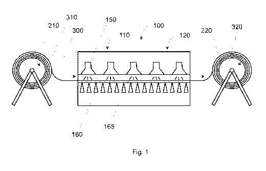
Figure 1 shows a device according to the invention, in a horizontal
configuration.
The device has a first coiler 210 with a sheet steel coil 310 placed onto it.
The first
coiler 310 consists of a wound-up Al-Si-coated steel sheet 300 in the form of
a
strip. Rotating the coiler 210 clockwise causes the steel sheet 300 to be
unwound
and fed into the furnace 100. In this process, a feed mechanism can have guide
rollers (not shown here) in addition to the first coiler 210. The furnace 100
has a
first section 110 that is heated up to a temperature at which the Al-Si of the
coating diffuses into the surface of the steel sheet 300. At the same time,
iron
diffuses out of the substrate of the steel sheet into the Al-Si. A refractory
aluminum-silicon-iron alloy is formed on the surface of the steel sheet. In
this
CA 02915440 2015-12-14
11
process, the furnace is heated up by means of heaters 150 and a hot-air
cushion
165 that is created under the steel sheet 300 by means of hot-air nozzles 160.
The
steel sheet 300 floats on the hot-air cushion through the furnace 100 without
touching the latter. Additional support or guide elements such as, for
example,
rollers or the like, are not necessary. This rules out any damaging reaction
between the molten Al-Si and these support and/or guide elements. The heaters
150 are gas burners. However, electric infrared heaters or hot-air heaters,
for
example, are likewise conceivable. The length of the first furnace section is
dimensioned as a function of the rate at which the steel sheet 300 passes
through
the furnace in such a way that the steel sheet is heated up to the diffusion
temperature of, for instance, 930 C to 950 C [1706 F to 1742 F] and this
temperature is maintained for the requisite diffusion time. By the same token,
an
optional final annealing time is taken into consideration in dimensioning the
length of the first furnace section. There is a second furnace section 120
downstream from the first furnace section 110 as seen in the direction of
conveyance of the steel sheet. The temperature management in the second
furnace
section 120 and the length of the second furnace section are dimensioned in
such a
way that the steel sheet is cooled down at a cooling rate of less than 25
K/sec to
the temperature range in which a ferrite-pearlite structure is formed, so that
a
blank can be subsequently stamped out of the steel sheet.
Downstream from the second furnace section 120, there is a take-off mechanism
having a second coiler 220. The second coiler 220 likewise turns in the
clockwise
direction, as a result of which the pretreated steel sheet is rewound to form
a
second coil 320. The take-off mechanism can have guide rollers (not shown
here)
in addition to the second coil 320.
Figure 2 shows a device according to the invention, in a vertical
configuration.
The furnace 100 is configured as a tower that is oriented essentially
vertically.
The steel sheet 300 is conveyed through the furnace 100 from the top to the
bottom. Owing to the vertical construction, there is no need for any measures
such
CA 02915440 2015-12-14
12
as the provision of hot-air cushions or cable pulls in order to guide the
steel sheet
contactlessly all the way through the furnace 100. The conveyance direction
from
the top to the bottom facilitates the temperature management in the furnace
since
the cooler second furnace section 120 is situated below the first furnace
section
110, which is heated up to the diffusion temperature. Since there is no need
for a
hot-air cushion 165, heaters 150 are provided on both sides of the furnace 100
in
order to ensure a homogenous heating of both surfaces of the steel sheet 300.
In
the case of the horizontal configuration, these heaters can be in the form of
gas
burners or hot-air heaters, or else, for instance, in the form of electric
radiant
heaters.
The guide and take-off mechanisms for the steel sheet 300 are configured
analogously to those in the horizontal configuration.
The embodiments shown here constitute merely examples of the present invention
and therefore must not be construed in a limiting fashion. Alternative
embodiments considered by the person skilled in the art are likewise
encompassed
by the scope of protection of the present invention.
CA 02915440 2015-12-14
13
List of reference numerals
100 furnace
110 first furnace section
120 second furnace section
150 heater
160 hot-air nozzle
165 hot-air cushion
210 first coiler
220 second coiler
300 steel sheet
310 first sheet steel coil
320 second sheet steel coil