Language selection

Search

Patent 2915715 Summary

Third-party information liability

Some of the information on this Web page has been provided by external sources. The Government of Canada is not responsible for the accuracy, reliability or currency of the information supplied by external sources. Users wishing to rely upon this information should consult directly with the source of the information. Content provided by external sources is not subject to official languages, privacy and accessibility requirements.

Claims and Abstract availability

Any discrepancies in the text and image of the Claims and Abstract are due to differing posting times. Text of the Claims and Abstract are posted:

  • At the time the application is open to public inspection;
  • At the time of issue of the patent (grant).
(12) Patent Application: (11) CA 2915715
(54) English Title: FLOATING CONSTRUCTION
(54) French Title: CONSTRUCTION FLOTTANTE
Status: Deemed Abandoned and Beyond the Period of Reinstatement - Pending Response to Notice of Disregarded Communication
Bibliographic Data
Abstracts

English Abstract

7Abstract A floating construction (1) comprising a container (2) filled fully or partially with water, the lower portion of the container being located within a surrounding body of water and the water surface level of the surrounding body of water be- ing substantially lower that the water surface level inside the container, the container comprising transparent walls or walls with transparent sections and at least one open opening for entering the container, which at least one open opening is located below the surface level of the surrounding body of water, and which floating construction comprises space (9) for spectators observing activities taking place inside the container, wherein the floating construction (1) comprises at least one ballast tank (3, 3'), which ballast tank is connected to the container (2) with a controllable pressure connection (4, 5, 4', 5'), and which ballast tank has controllable water connection (6, 7, 6', 7') to the surrounding body of water.


French Abstract

L'invention concerne une construction flottante (1) comprenant un contenant (2) entièrement ou partiellement rempli d'eau, la partie inférieure du contenant étant située dans un corps d'eau environnant et le niveau de surface d'eau du corps d'eau environnant étant sensiblement inférieur au niveau de surface d'eau à l'intérieur du contenant, le contenant comprenant des parois transparentes ou des parois ayant des sections transparentes et au moins une ouverture ouverte pour entrer dans le contenant, au moins une ouverture ouverte étant située au-dessous du niveau de surface du corps d'eau environnant, et laquelle construction flottante comprend un espace (9) pour des spectateurs observant des activités ayant lieu à l'intérieur du contenant, la construction flottante (1) comprenant au moins une citerne de ballast (3, 3'), laquelle citerne de ballast est reliée au contenant (2) au moyen d'un raccordement pression pouvant être commandé (4, 5, 4', 5'), et laquelle citerne de ballast a un raccordement eau pouvant être commandé (6, 7, 6', 7') au corps d'eau environnant.

Claims

Note: Claims are shown in the official language in which they were submitted.

6
Claims
1. A floating construction (1) comprising a container (2) filled fully or
partially
with water, the lower portion of the container being located within a surround-
ing body of water and the water surface level of the surrounding body of water
being substantially lower that the water surface level inside the container,
the
container comprising transparent walls or walls with transparent sections and
at least one open opening for entering the container, which at least one open
opening is located below the surface level of the surrounding body of water,
and which floating construction comprises space (9) for spectators for observ-
ing activities taking place inside the container, characterized in that the
float-
ing construction (1) comprises at least one ballast tank (3, 3'), which
ballast
tank is connected to the container (2) with a controllable pressure connection
(4, 5, 4', 5'), and which ballast tank has controllable water connection (6,
7, 6',
7') to the surrounding body of water.
2. A floating construction (1) according to claim 1, wherein the pressure
connection (4, 5, 4', 5') is located between the upper portion of the at least
one
ballast tank (3, 3') and the upper portion of the container (2).
3. A floating construction (1) according to claim 1 or 2, wherein the
floating
construction (1) comprises two substantially same sized ballast tanks (3, 3')
lo-
cated on opposite sides of the container (2), and both of the ballast tanks
are
connected to the container with a controllable pressure connection (4, 5, 4',
5').
4. A floating construction (1) according to any of claims 1-3, wherein the
floating construction (1) comprises pumping system (10, 10') for controlling
the
amount of water inside the at least one ballast tank (3, 3') and/or inside the
container (2).
5. A floating construction (1) according to any of claims 1-4, wherein the
controllable pressure connection and/or the controllable water connection is
implemented with pipes (4, 4', 6, 6') and controllable valves (5, 5', 7, 7').
6. A floating construction (1) according to any of claims 1-5, wherein the
floating construction (1) comprises a control system (8) for controlling the
con-
trollable pressure connection (4, 5, 4', 5') and/or the controllable water
connec-
tion (6, 7, 6', 7').

Description

Note: Descriptions are shown in the official language in which they were submitted.


CA 02915715 2015-12-16
WO 2014/202820 PCT/F12013/050669
1
Floating construction
The present invention relates to a floating construction comprising a vessel
or
container filled fully or partially with water and the lower portion of the
contain-
er is located within a surrounding body of water, wherein the walls of the con-
tainer are transparent or contain transparent sections, and the container com-
prises one or more open openings for entering the container, which open
opening or openings are located below surface level of the surrounding body
of water, and the floating construction comprising a space for spectators for
observing actions taking place in the container.
Patent application PCT/FI2012/050726 discloses an apparatus for underwater
activities, which apparatus comprises a vessel or container filled fully or
partial-
ly with water, which vessel comprises one or more open openings for entering
the vessel, wherein the lower portion of the vessel is located within a body
of
water, all of the one or more open openings for entering the vessel are
located
in that portion of the vessel which is located under the surface level of the
body
of water, and the walls of the vessel are transparent, or the walls comprise
sections that are transparent, for allowing observation of the activities
taking
place inside the vessel from outside of the vessel. One disclosed embodiment
comprises a floating platform connected to this type of an apparatus, wherein
the floating platform may be equipped with a space for spectators, including
seating and other types of services for the spectators.
With this type of floating platform the water mass inside the container or
vessel
is significant, and causes problems for the floating construction and its
struc-
tural integrity especially in situations where the water mass inside the
container
needs to be removed quickly.
The present invention provides a solution for emptying the water filled
contain-
er within a floating construction safely, quickly and in controlled manner.
In the floating construction according to the present invention at least one
bal-
last tank, which ballast tank has a water connection to the surrounding body
of
water, is connected to the container with a controllable pressure connection.

CA 02915715 2015-12-16
WO 2014/202820 PCT/F12013/050669
2
In the solution according to the present invention, when the pressure connec-
tion between the ballast tank or tanks and the container is opened, the water
inside the container can escape from the container to the surrounding body of
water, and the underpressure or vacuum created by the water escaping the
container is used to fill the ballast tank. This way the water filling the
ballast
tank compensates the water escaping from the container.
In the context of the present invention a controllable pressure connection
means suitable connection between the ballast tank or tanks and the container
which connection, when closed allows a pressure difference between inner
side of the ballast tank or tanks and inner side of the container, and when
opened allows the pressure difference to equalize.
In the context of the present invention a controllable water connection
between
the ballast tank or tanks and the surrounding body of water means suitable
connection allowing water from the surrounding body of water to enter and exit
the ballast tank or tanks in controlled manner.
Both the controllable pressure connection and the controllable water connec-
tion may be implemented with pipe and control valve arrangement, for exam-
ple.
In the floating construction of the invention, the container is filled fully
or par-
tially with water, which partial filling of the container means that inside
the con-
tainer there is sufficient amount of water to allow underwater activities to
take
place within the amount of water in the container, and allow these activities
to
be observed though the walls of the container. Thus the water surface level in-
side the container in operation condition is significantly higher than the
water
surface level of the surrounding body of water. This also means that the
water,
and possible remaining air, inside the container is in underpressure so that
wa-
ter remains inside the container and does not escape through the open open-
ing(s) located below the surface level of the surrounding body of water.
In the floating construction of the invention the pressure connection is advan-
tageously located between the upper portion of the at least one ballast tank
and the upper portion of the container. This embodiment allows faster equali-
zation of the pressure difference, since the pressure difference is at maximum
in the starting situation.

CA 02915715 2015-12-16
WO 2014/202820 PCT/F12013/050669
3
Advantageously in the floating construction according to the invention there
is
at least two substantially same sized ballast tanks located on opposite sides
of
the container, and both of the ballast tanks are connected to the container
with
a controllable pressure connection. Use of a plurality of ballast tanks allows
faster emptying of the container, and equal filling of the ballast tanks which
leads to more controlled emptying process of the container.
The floating construction according to the present invention may also comprise
a pumping system, which can be used to control the amount of water inside
the at least one ballast tank and/or inside the container.
The floating construction of the invention advantageously comprises a control
system for controlling the controllable pressure connection and/or the control-
lable water connection, as well as other relating apparatuses, such as pumps,
for example.
The features defining a floating construction according to the invention are
more precisely presented in claim 1. Dependent claims disclose advantageous
embodiments and features of the invention.
Exemplifying embodiments of the invention and their advantages are explained
in greater detail below in the sense of example and with reference to accom-
panying drawings, where:
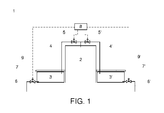
Figure 1 shows schematically a cross-sectional view of an embodiment of
the invention, and
Figure 2 shows schematically a cross-sectional view of an alternative
embodiment of the invention.
Figure 1 shows schematically a cross sectional view of a floating construction
1, which comprises a container 2 for water which container is air and water-
tight, with the exception of the open bottom surface. On both sides of the con-
tainer 2 is located ballast tanks 3, 3'. Upper portions of the ballast tanks
3, 3'
are connected to the upper portion of the container through controllable pres-
sure connection in form of pipes 4, 4' and controllable valves 5, 5', which
con-
trolled pressure connections connects the inner sides of the ballast tanks and
the container. The ballast tanks 3, 3' are also equipped with controllable
water
connection to the surrounding body of water, when the floating construction 1

CA 02915715 2015-12-16
WO 2014/202820 PCT/F12013/050669
4
is floating in the body of water, in form of pipes 6, 6' and controllable
valves 7,
7'. The controllable valves 5, 5' and 7, 7' are controlled with a control
system 8.
On top of the ballast tanks 3, 3' and next to the container 2 is located a
deck
area 9, 9', from where spectators can observe activities taking place inside
the
container through transparent walls of the container.
When the floating construction 1 is floating on a surrounding body of water
and
in operating condition, the container 2 is full or substantially full with
water and
the lower edges of the side walls of the container are located below the sur-
face level of the surrounding body of water. Further, the controllable valves
5,
5' are closed so that the water inside the container 2 remains inside the con-
tainer and the surface level of the water inside the container remains substan-
tially higher than the surface level of the surrounding body of water. In this
op-
erating condition, the ballast tanks 3, 3' are substantially empty in order to
compensate the weight of the water-filled container 2.
When the container 2 needs to be emptied, controllable valves 5, 5' and 7, 7'
are opened through the control system 8, and air from ballast tanks 3, 3' can
enter to the upper portion of the container and thus lower the pressure differ-
ence between the container and the ballast tanks, which allows the water es-
cape from the container through the open bottom surface of the container to
the surrounding body of water, and the surface level of the water inside the
container lowers quickly.
The underpressure created inside the ballast tanks 3, 3' by the opening of the
controllable valves 5, 5' forces water to enter to the ballast tanks though
pipes
6, 6' and open controllable valves 7, 7'. This way the weight of the water
enter-
ing to the ballast tanks 3, 3' compensates the weight of the water escaping
from the container 2.
Figure 2 shows schematically a cross-sectional view of an alternative embodi-
ment of the invention, where the embodiment of figure 1 is equipped with
pumps for filling the container 2 with water.
In the embodiment of figure 2, pumps 10, 10' are located on a bypass lines at-
tached to the pipes 4, 4'. The pumps 10, 10', and the bypass line system, es-
pecially controllable valves 11, 11', 12, 12' and 13, 13', are controlled with
the
control system 8.

CA 02915715 2015-12-16
WO 2014/202820 PCT/F12013/050669
When the container 2 of the floating construction 1 is filled, the
controllable
valves 5, 5', 11, 11' and 12, 12' are opened, and controllable valves 13, 13'
are
closed to allow air to move through the bypass line and pumps 10, 10', which
pumps are vacuum pumps. Further, the controllable valves 7, 7' are also
5 opened. Then the pumps 10, 10' are activated, and they start to suck air
from
the container 2, and thus create underpressure inside the container, through
their suction sides, and blow air to the ballast tanks 3, 3', and thus create
overpressure inside the ballast tanks, through their delivery sides.
The underpressure inside the container 2 causes the water surface level to
raise inside the container and water to enter the container, and the overpres-
sure inside the ballast tanks 3, 3' causes the water inside the ballast tanks
to
escape through pipes 6, 6' and open controllable valves 7, 7' to the surround-
ing body on water. This way the emptying of the ballast tanks 3, 3' compen-
sates the filling of the container 2.
Once the container 2 is filled, or the water surface level inside the
container
has reached sufficient height, the pumps 10, 10' are stopped and controllable
valves 5, 5' and 7, 7' are closed, so that the pressure difference between the
ballast tanks 3, 3' and the inside of the container 2 in preserved and water
re-
mains inside the container.
The specific exemplifying embodiments of the invention shown in figures and
discussed above should not be construed as limiting. A person skilled in the
art
can amend and modify the exemplary floating construction described above in
many evident ways within scope of attached claims. Thus the invention is not
limited merely to the embodiments described above.

Representative Drawing
A single figure which represents the drawing illustrating the invention.
Administrative Status

2024-08-01:As part of the Next Generation Patents (NGP) transition, the Canadian Patents Database (CPD) now contains a more detailed Event History, which replicates the Event Log of our new back-office solution.

Please note that "Inactive:" events refers to events no longer in use in our new back-office solution.

For a clearer understanding of the status of the application/patent presented on this page, the site Disclaimer , as well as the definitions for Patent , Event History , Maintenance Fee  and Payment History  should be consulted.

Event History

Description Date
Inactive: IPC expired 2020-01-01
Application Not Reinstated by Deadline 2019-06-19
Inactive: Dead - RFE never made 2019-06-19
Inactive: Abandon-RFE+Late fee unpaid-Correspondence sent 2018-06-19
Change of Address or Method of Correspondence Request Received 2018-01-12
Inactive: Cover page published 2016-02-17
Inactive: Notice - National entry - No RFE 2016-01-04
Application Received - PCT 2016-01-04
Inactive: First IPC assigned 2016-01-04
Inactive: IPC assigned 2016-01-04
National Entry Requirements Determined Compliant 2015-12-16
Application Published (Open to Public Inspection) 2014-12-24

Abandonment History

There is no abandonment history.

Maintenance Fee

The last payment was received on 2018-05-23

Note : If the full payment has not been received on or before the date indicated, a further fee may be required which may be one of the following

  • the reinstatement fee;
  • the late payment fee; or
  • additional fee to reverse deemed expiry.

Please refer to the CIPO Patent Fees web page to see all current fee amounts.

Fee History

Fee Type Anniversary Year Due Date Paid Date
MF (application, 2nd anniv.) - standard 02 2015-06-19 2015-12-16
Basic national fee - standard 2015-12-16
MF (application, 3rd anniv.) - standard 03 2016-06-20 2016-05-20
MF (application, 4th anniv.) - standard 04 2017-06-19 2017-05-23
MF (application, 5th anniv.) - standard 05 2018-06-19 2018-05-23
Owners on Record

Note: Records showing the ownership history in alphabetical order.

Current Owners on Record
WATERBOX OY
Past Owners on Record
JUHA SAARANEN
Past Owners that do not appear in the "Owners on Record" listing will appear in other documentation within the application.
Documents

To view selected files, please enter reCAPTCHA code :


To view images, click a link in the Document Description column. To download the documents, select one or more checkboxes in the first column and then click the "Download Selected in PDF format (Zip Archive)" or the "Download Selected as Single PDF" button.

List of published and non-published patent-specific documents on the CPD .

If you have any difficulty accessing content, you can call the Client Service Centre at 1-866-997-1936 or send them an e-mail at CIPO Client Service Centre.


Document
Description 
Date
(yyyy-mm-dd) 
Number of pages   Size of Image (KB) 
Description 2015-12-16 5 244
Representative drawing 2015-12-16 1 5
Drawings 2015-12-16 1 14
Claims 2015-12-16 1 50
Abstract 2015-12-16 1 58
Cover Page 2016-02-17 2 42
Notice of National Entry 2016-01-04 1 193
Courtesy - Abandonment Letter (Request for Examination) 2018-07-31 1 165
Reminder - Request for Examination 2018-02-20 1 117
National entry request 2015-12-16 5 115
International search report 2015-12-16 2 51
Maintenance fee payment 2018-05-23 1 25