Note: Descriptions are shown in the official language in which they were submitted.
CA 02916172 2015-12-18
WO 2014/203233
PCT/1E2014/000013
1
"A log splitter, and a method for splitting a log"
The present invention relates to a log splitter, and in particular, to a log
splitter for coupling to a working
arm, for example, a dipper arm of a prime mover, such as an earth working
machine. The invention also
relates to a working arm of a prime mover comprising the log splitter coupled
thereto, and the invention
also relates to a prime mover comprising a working arm with the log splitter
attached to the working arm.
Further the invention relates to a method for splitting a log with the log
splitter.
Log splitters for splitting logs which are suitable for mounting to a prime
mover, for example, an earth
working machine, a tractor or the like are known. Such a log splitter is
disclosed in U.S. Patent
Specification No. 5,803,141 of Patterson, where a log splitter is adapted for
mounting to a working arm,
namely, a dipper arm of an earth working machine. In the log splitter
disclosed in U.S. Specification No.
5,803,141, the log splitter is coupled to the dipper arm by a vertically
extending shaft. The shaft is rigidly
connected to the log splitter, and is rotatably carried in a mounting system
attached to the dipper arm. A
drive motor rotates the shaft for rotating the log splitter about a vertical
axis. The log splitter comprises an
elongated horizontally extending support element which is rigidly mounted on
the lower end of the
vertically extending shaft. A splitter blade extends downwardly from one end
of the support element, and
an anvil is urged by a ram along the support element towards the splitting
element for urging a log into
engagement with the splitting element for splitting the log. However, the log
splitter disclosed in U.S.
Specification No. 5,803,141 is suitable only for splitting logs which are
lying horizontally on the ground
with the grain of the log lying horizontally.
There is therefore a need for a log splitter which is suitable for picking up
a log and for splitting a log,
irrespective of the orientation of the log or the direction of the grain of
the log in its rest state when lying on
the ground or lying in a pile of logs.
The present invention is directed towards providing such a log splitter. The
invention is also directed
towards providing a working arm of a prime mover comprising the log splitter
mounted thereon.
Additionally, the invention is directed towards a prime mover comprising a
working arm and the log splitter
mounted on the working arm. Further, the invention is directed towards a
method for splitting a log with
the log splitter.
According to the invention there is provided a log splitter comprising a
support element, an anvil supported
CA 02916172 2015-12-18
WO 2014/203233
PCT/1E2014/000013
2
on the support element, a splitting element supported on the support element,
one of the splitting element
and the anvil being moveable from a receiving state with the splitting element
and the anvil spaced apart
from each other and defining an open mouth therebetween for receiving a log,
towards the other one of
the splitting element and the anvil to a splitting state with the splitting
element and the anvil co-operating
with each other to split the log, a drive means for urging the moveable one of
the splitting element and the
anvil between the receiving state and the splitting state, a mounting means
configured for mounting the
support element to a working arm of a prime mover, the support element being
pivotally coupled to the
mounting means about a main pivot axis, and being pivotal about the main pivot
axis relative to the
mounting means between a first state with the open mouth defined between the
splitting element and the
anvil facing in a first direction, and a second state with the open mouth
defined between the splitting
element and the anvil facing in a second direction, the second direction
extending at an angle greater than
zero relative to the first direction, and an urging means for urging the
support element relative to the
mounting means about the main pivot axis between the first state and the
second state.
In one embodiment of the invention the angle at which the second direction
extends relative to the first
direction is at least 45 . Preferably, the angle at which the second direction
extends relative to the first
direction is at least 90 . Advantageously, the angle at which the second
direction extends relative to the
first direction is approximately 95 .
In another embodiment of the invention the support element is pivotal about
the main pivot axis from the
first state to the second state through an angle greater than zero relative to
the mounting means.
Preferably, the support element is pivotal about the main pivot axis from the
first state to the second state
through an angle of at least 45 relative to the mounting means.
Advantageously, the support element is
pivotal about the main pivot axis from the first state to the second state
through an angle of at least 90
relative to the mounting means. Ideally, the support element is pivotal about
the main pivot axis from the
first state to the second state through an angle of approximately 95 relative
to the mounting means.
Preferably, the support element is pivotal about the main pivot axis relative
to the mounting means
through a plurality of intermediate states between the first and second
states.
In one aspect of the invention the anvil extends in a leading direction from
the support element and
terminates in a distal leading edge spaced apart from the support element, the
open mouth defined
between the splitting element and the anvil facing generally in the leading
direction from the support
CA 02916172 2015-12-18
WO 2014/203233
PCT/1E2014/000013
3
element.
In another aspect of the invention the support element comprises an elongated
support element.
Preferably, the main pivot axis extends in a direction substantially
transversely relative to the support
element, and substantially transversely relative to the leading direction from
which the anvil extends from
the support element.
In another aspect of the invention the mounting means is adapted for coupling
to a coupling element of a
working arm of a prime mover. Preferably, the mounting means is adapted for
coupling to a coupling
element of a working arm of a prime mover, the coupling element of the working
arm of the prime mover
being pivotally coupled to the working arm about a coupler pivot axis, and the
mounting means is
configured for coupling to the coupling element with the coupler pivot axis
extending in a direction
substantially perpendicularly to the main pivot axis, and substantially
parallel to the leading direction from
which the anvil extends from the support element. Advantageously, the mounting
means comprises a
mounting element configured to carry a coupling member adapted for engagement
by a coupling element
of a working arm of a prime mover.
Preferably, the coupling member is configured for releasable engagement by a
quick release mechanism
of a coupling element of a working arm of a prime mover.
In one aspect of the invention the mounting element comprises a mounting
plate.
In another aspect of the invention the anvil is rigidly mounted on the support
element.
In a further aspect of the invention the splitting element is moveable between
the receiving state and the
splitting state longitudinally along the support element.
In one embodiment of the invention a guide means is provided for guiding the
splitting element between
the receiving state and the splitting state. Preferably, the guide means is
mounted on the support
element. Advantageously, the splitting element is slideably engageable with
the guide means.
In another embodiment of the invention the splitting element comprises a
splitter blade. Preferably, the
CA 02916172 2015-12-18
WO 2014/203233
PCT/1E2014/000013
4
splitter blade extends in a direction substantially parallel to the leading
direction from which the anvil
extends from the support element. Advantageously, the splitter blade extends
in a direction substantially
perpendicular to the main pivot axis.
In another aspect of the invention the splitter blade terminates in a cutting
edge. Preferably, the cutting
edge of the blade extends in a direction from the support element
substantially parallel to the leading
direction from which the anvil extends from the support element, and at an
acute angle relative to the
support element towards the anvil.
In one embodiment of the invention the drive means is operably coupled between
the support element
and the splitting element.
Preferably, the drive means is selectively and releasably coupleable to the
support element in an
operative state. Advantageously, the drive means when released from the
support element is moveable
between the operative state and an inoperative state.
In another aspect of the invention the drive means comprises a primary
hydraulic ram.
In a further aspect of the invention the urging means is operably coupled
between the mounting means
and the support element. Preferably, the urging means comprises a secondary
hydraulic ram.
In one embodiment of the invention the anvil adjacent the leading edge thereof
tapers towards the leading
edge for engaging between a log and a surface on which the log is supported.
Preferably, the anvil
defines an inner major surface facing towards the splitting element, and an
opposite outer major surface
facing away from the splitting element, the outer major surface being
chamfered adjacent the leading
edge of the anvil to form the tapering portion of the anvil adjacent the
leading edge.
In another embodiment of the invention a projecting element extends sidewardly
from the anvil adjacent
one side thereof for engaging and manoeuvring a log. Preferably, the
projecting element tapers towards a
distal end thereof.
In another embodiment of the invention a support member is provided extending
sidewardly from at least
one side of the support element for supporting a log in the log splitter when
the log splitter is oriented with
CA 02916172 2015-12-18
WO 2014/203233
PCT/1E2014/000013
the open mouth defined between the splitting element and the anvil facing in a
generally upwardly
direction. Preferably, a pair of support members are provided on respective
opposite sides of the support
element. Advantageously, each support member is releasably coupleable to the
support element.
5 In one aspect of the invention each support member is mounted on a
framework which is releasably
coupleable to the support element. =
In another aspect of the invention a manual control means is provided for
manually controlling the drive
means. Preferably, the manual control means comprises a safety interlock
system, the safety interlock
113 system being configured so that the two hands of an operator are
required to manually operate the drive
means through the manual control means.
In a further aspect of the invention the distance of travel of the moveable
one of the splitting element and
the anvil from the other one of the splitting element and the anvil to the
receiving state is selectable.
Additionally, the invention provides a working arm of a prime mover, the
working arm comprising the log
splitter according to the invention, the log splitter being coupled to the
working arm by the mounting
- means.
In one embodiment of the invention the working arm terminates in a coupling
element, and the mounting
means is coupled to the coupling element.
Preferably, the mounting means is releasably coupleable to the coupling
element.
In one embodiment of the invention the coupling element is pivotally coupled
to the working arm, and is
pivotal about a coupler axis relative to the working arm, the coupler axis
extending in a direction
substantially perpendicular to the main pivot axis and substantially parallel
to the leading direction from
which the anvil extends from the support element.
In another embodiment of the invention the working arm comprises a dipper arm,
and the coupling
element is pivotally coupled to the dipper arm about the coupler pivot axis.
Further the invention provides a prime mover comprising a working arm
according to the invention.
Preferably, the drive means and the urging means are powered by an on board
power system of the prime
CA 02916172 2015-12-18
WO 2014/203233
PCT/1E2014/000013
6
mover.
Additionally the invention provides a method for splitting a log, the method
comprising providing a log
splitter according to the invention, coupling the log splitter to a working
arm of a prime mover by coupling
the mounting means to a coupling element of the working arm, operating the
working arm for urging the
log splitter towards a log to be split until the log is located in the open
mouth defined between the splitting
element and the anvil, and operating the drive means of the log splitter for
urging the moveable one of the
splitting element and the anvil from the receiving state to the splitting
state for splitting the log.
In one embodiment of the invention the urging means of the log splitter is
operated for pivoting the support
element about the main pivot axis relative to the mounting means to orient the
open mouth defined
between the splitting element and the anvil to face towards a log to be split.
In another embodiment of the invention the urging means of the log splitter is
operated for pivoting the
support element about the main pivot axis relative to the mounting means for
configuring the anvil for
engaging beneath the log and between the log and the surface on which the log
is supported.
In another embodiment of the invention the urging means of the log splitter is
operated for urging the
support element from one of the first state and the second state to one of the
intermediate states for
configuring the anvil for engaging beneath the log between the log and the
surface on which the log is
supported.
In a further embodiment of the invention the coupling element of the working
arm is pivoted about the
coupler pivot axis relative to the working arm for orienting the log splitter
with the open mouth defined
between the splitting element and the anvil facing in a generally upwardly
direction for facilitating manual
feeding of a log into the open mouth defined between the splitting element and
the anvil.
Preferably, the drive means of the log splitter is manually controlled when
the log splitter is oriented with
the open mouth defined between the splitting element and the anvil facing in a
generally upwardly
direction.
The advantages of the invention are many. A particularly important advantage
of the invention is that the
log splitter can pick up a log in the open mouth defined between the splitting
element and the anvil
irrespective of the orientation in which the log is lying on the ground, in a
pile of logs or lying or supported
CA 02916172 2015-12-18
WO 2014/203233
PCT/1E2014/000013
7
elsewhere, and furthermore, the log is picked up and engaged in the open mouth
of the log splitter with
the grain of the log correctly aligned with the splitting element, so that the
log can be immediately split
without requiring any further manoeuvring of the log in the open mouth. This
advantage is achieved by
virtue of the fact that the support element is pivotally coupled to the
mounting means about the main pivot
axis, and is pivotal about the main pivot axis relative to the mounting means
between a first state with the
open mouth defined between the splitting element and the anvil facing a first
direction, and a second state
with the open mouth defined between the splitting element and the anvil facing
in a second direction,
whereby the second direction extends at an angle greater than zero relative to
the first direction.
Accordingly, there is no need to manoeuvre the log prior to picking up of the
log by the log splitter, and
once picked up, there is also no need to manoeuvre the log in the open mouth
of the blade splitter. This
leads to significant time saving and manpower saving.
Another advantage of the invention is that the anvil can be engaged beneath a
log and between the log
and the surface on which the log is standing irrespective of the orientation
of the log or the surface on
which the log is standing.
Another advantage of the log splitter according to the invention is that an
earth working machine to which
the log splitter is attached can be driven along a public road while the log
splitter is still attached to the
dipper arm. This advantage is achieved by virtue of the fact that the drive
means is selectively
positionable between an operative state and an inoperative state whereby the
length of the log splitter is
substantially similar to the length of the support element.
These and other advantages of the invention will become readily apparent to
those skilled in the art by the
following description of some preferred non-limiting embodiments thereof,
which are given by way of
example only, with reference to the accompanying drawings, in which:
Fig. 1 is a perspective view of a log splitter according to the invention with
a portion of the log
splitter in an inoperative state,
Fig. 2 is another perspective view of the log splitter of Fig. 1 with the
portion of the log splitter in
the same state as that of Fig. 1,
Fig. 3 is a side elevational view of the log splitter of Fig. 1 with the
portion of the log splitter in the
CA 02916172 2015-12-18
WO 2014/203233
PCT/1E2014/000013
8
same state as that of Fig. 1,
Fig. 4 is an end elevational view of the log splitter of Fig. 1 with the
portion of the log splitter in
the same state as that of Fig. 1,
Fig. 5 is another end elevational view of the log splitter of Fig. 1 from the
end opposite to that of
Fig. 4 with the portion of the log splitter in the same state as that of Fig.
1,
Fig. 6 is a top plan view of the log splitter of Fig. 1 with the portion of
the log splitter in the same
state as that of Fig. 1,
Fig. 7 is a side elevational view of the log splitter of Fig. 1 from the side
opposite to that of Fig. 3
with the portion of the log splitter in the same state as that of Fig. 1,
Fig. 8 is a perspective view of the log splitter of Fig. 1 in a different
state to that of Fig. 1, with the
portion of the log splitter in an operative state, and another portion of the
log splitter in a
receiving state,
Fig. 9 is another perspective view of the log splitter of Fig. 1 in the state
of Fig. 8 and with a
portion of the log splitter in a splitting state,
Fig. 10 is a side elevational view of the log splitter of Fig. 1 illustrating
the log splitter in two
states,
Fig. 11 is a perspective view of the log splitter of Fig. 1 illustrated
mounted on a dipper arm of a
prime mover,
Fig. 12 is another perspective view of the log splitter of Fig. 1 also
illustrated mounted on the
dipper arm of a prime mover,
Fig. 13 is a perspective view of the log splitter of Fig. 1 differently
configured to the configuration
of Fig. 1,
CA 02916172 2015-12-18
WO 2014/203233
PCT/1E2014/000013
9
Fig. 14 is another perspective view of the log splitter of Fig. 1 configured
as in Fig. 13,
Fig. 15 is a further perspective view of the log splitter of Fig. 1 configured
as in Fig. 13,
Fig. 16 is an underneath perspective view of the log splitter of Fig. 1
configured as in Fig. 13,
Fig. 17 is a side elevational view of the log splitter of Fig. 1 configured as
in Fig. 13,
Fig. 18 is an end elevational view of the log splitter of Fig. 1 configured as
in Fig. 13,
Fig. 19 is an end elevational view of the log splitter of Fig. 1 from the
other end to that of Fig. 18
configured as in Fig. 13,
Fig. 20 is a transverse cross-sectional end elevational view of the log
splitter of Fig. 1 configured
= as in Fig. 13 on the line XX-XX of Fig. 17.
Fig. 21 is an exploded perspective view of some of the parts of the log
splitter of Fig. 1,
Fig. 22 is a side elevational view of a log splitter according to another
embodiment of the
invention in a configuration similar to the configuration illustrated in Figs.
1 to 12 of the log splitter
of Figs. 1 to 21.
Fig. 23 is a perspective view of the log splitter of Fig. 22 in the
configuration of Fig. 22, but in a
different state to that of Fig. 22,
Fig. 24 is another perspective view of the log splitter of Fig. 22 in the
orientation of Fig. 22, but in
a state intermediate to that of Figs. 22 and 23,
Fig. 25 is a further perspective view of the log splitter of Fig. 22 in the
configuration of Fig. 22, but
in the state of Fig. 23,
Fig. 26 is a further perspective view of the log splitter of Fig. 22 in the
configuration of Fig. 22 and
in the state of Fig. 23,
CA 02916172 2015-12-18
WO 2014/203233
PCT/1E2014/000013
Fig. 27 is a side elevational view of the log splitter of Fig. 22 in the
configuration of Fig. 13 to 20
of the log splitter of Figs. 1 to 21, and
Fig. 28 is another perspective view of the log splitter of Fig. 22 in the
configuration of Fig. 22, and
5 with a portion of the log splitter in the inoperative state.
Referring to the drawings and initially to Figs. 1 to 21 thereof, there is
illustrated a log splitter according to
the invention, indicated generally by the reference numeral 1, for mounting on
a working arm, namely, a
dipper arm 2 of a prime mover, such as an earth moving machine (not shown) for
splitting logs. The
10 combination of the dipper arm 2 and the log splitter 1 is also according
to the invention, as is the prime
mover (not shown) with the dipper arm 2 and the log splitter 1 attached
thereto. The log splitter 1 is
illustrated in one configuration in Figs. 1 to 12, and in another
configuration in Figs. 13 to 20. In the
configuration of Figs. 1 to 12, the log splitter is configured mounted on the
dipper arm 2 of an earth
working machine, wherein the log splitter 1 is operated by an operator from
the cab of the earth working
machine. In the configuration of Figs. 13 to 20, the log splitter 1, while
still mounted on the dipper arm 2 of
the earth working machine, is manually operable for splitting relatively small
logs, which are manually fed
to the log splitter 1, as will be described below with reference to Figs. 13
to 20. Initially, the log splitter 1
will be described in the configuration of Figs. 1 to 20.
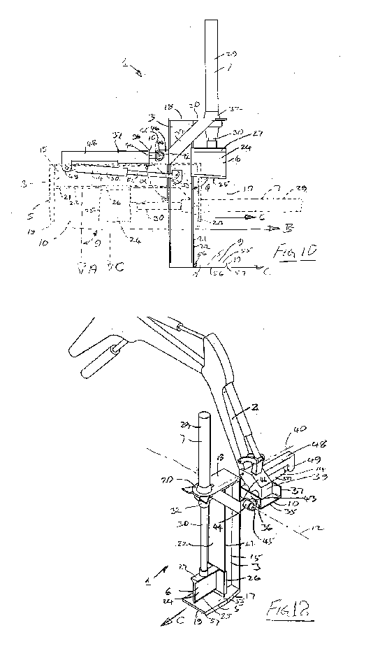
Turning now to Figs. 1 to 12, the log splitter 1 comprises an elongated
support element 3 having an anvil 5
extending from one end thereof and a splitting element 6 slideably mounted on
the support element 3 and
urgeable by a drive means, namely, a primary hydraulic ram 7 between a
receiving state illustrated in
Figs. 8 and 10 and defining with the anvil 5 an open mouth 9 for receiving a
log 8 therein, to a splitting
state illustrated in Figs. 9 and 12 with the splitting element 6 co-operating
with the anvil 5 for splitting the
log.
A mounting means, namely, an inverted U-shaped mounting element 10 for
coupling the log splitter 1 to
the dipper arm 2 is pivotally coupled to the support element 3 with the
support element 3 pivotal relative to
the mounting element 10 about a main pivot axis 12. An urging means, namely, a
secondary hydraulic
ram 14 operably coupled between the mounting element 10 and the support
element 3 pivots the support
element 3 through an angle a relative to the mounting element 10 about the
main pivot axis 12 from a first
state, illustrated in broken lines in Fig. 10, with the open mouth 9 defined
between the splitting element 6
and the anvil 5 facing in a first direction relative to the mounting element
10, through a plurality of
CA 02916172 2015-12-18
WO 2014/203233
PCT/1E2014/000013
11
intermediate states, to a second state, illustrated in full lines in Fig. 10,
with the open mouth 9 defined
between the splitting element 6 and the anvil 5 extending in a second
direction relative to the mounting
element 10 with the second direction extending at an angle 0, relative to the
first direction. In Fig. 10 the
open mouth 9 defined between the splitting element 6 and the anvil 5 is
illustrated in broken lines facing in
the first direction, which is illustrated by the arrow A, and in the open
mouth 9 is illustrated in full lines in
Fig. 10 facing in the second direction, which is illustrated by the arrow B.
In this embodiment of the
invention the angles a and e are approximately 95 . However, the angles a and
8 may be any angle
greater than zero, and ideally, will be in the order of 900
.
Turning now in more detail to the construction of the log splitter 1, the
support element 3 comprises a
longitudinally extending main central member 15 provided by an I-section beam.
A pair of spaced apart
end plates 17 and 18 of steel plate material extend substantially
perpendicularly from the main central
member 15 at respective opposite ends thereof in a leading direction, namely,
the direction of the arrow C,
which is the direction that the log splitter 1 is urged towards a log to be
split. The end plate 17 forms the
anvil 5. The anvil 5 formed by the end plate 17 extends from the support
element 3 in the leading
direction, and terminates in a distal leading edge 19 spaced apart from the
support element 3. The end
plate 18 forms a mounting bracket 20 to which the primary hydraulic ram 7 is
coupled as will be described
below.
A guide means for guiding the splitting element 6 longitudinally along and
parallel to the support element 3
between the receiving state and the splitting state comprises an elongated
guide member 21, which
extends longitudinally along the support element 3, and in this embodiment of
the invention comprises
one of the webs 22 of the I-beam of the main central member 15.
The splitting element 6 comprises a splitter blade 24 of hardened steel plate
material welded to and
extending from a guide bracket 26. The guide bracket 26 is slideably
engageable with the guide member
21 of the support element 3 for guiding the splitting element 6 along the
support element 3 between the
receiving state and the splitting state. One edge of the splitter blade 24
extending from the guide bracket
26 forms a sharpened cutting edge 25 which faces towards and co-operates with
the anvil 5 for splitting a
log when the splitting element 6 is in the splitting state. The splitter blade
24 of the splitting element 6
extends substantially perpendicularly from the support element 3 in the
leading direction. The cutting
edge 25 of the splitter blade 24 is angled at an acute angle cp of
approximately 75 relative to the =support
element 3 towards the anvil 5, so that the splitter blade 24 progressively
engages a log as the splitting
CA 02916172 2015-12-18
WO 2014/203233
PCT/1E2014/000013
12
element 6 is being urged from the receiving state to the splitting state, and
also retains the log between
the splitting element 6 and the anvil 5. A connecting bracket 27 extending
from the guide bracket 26 is
welded to the splitter blade 24 along an edge of the splitter blade 24
opposite to the cutting edge 25 for
connecting the splitting element 6 to the primary hydraulic ram 7.
A housing 29 of the primary hydraulic ram 7 is releasably coupleable to the
mounting bracket 20, and a
piston rod 30 of the primary hydraulic ram 7 is coupled to the connecting
bracket 27 of the splitting
element 6. An opening 31 in the mounting bracket 20 accommodates the housing
29 of the primary
hydraulic ram 7 therethrough. In this embodiment of the invention the primary
hydraulic ram 7 is
selectively coupleable to the mounting bracket 20 in an operative state
illustrated in Figs. 8 to 10 and 12,
and is releasable from the mounting bracket 20 to be urged through the opening
31 into an inoperative
state illustrated in Figs. 1 to 7 and 11.
A releasable securing means for coupling the primary hydraulic ram 7 to the
mounting bracket 20
comprises a coupling flange 32 mounted on and extending around the housing 29
of the primary hydraulic
ram 7 and a screw 33 and a nut 28. A bore 41 extending through the coupling
flange 32 is alignable with
a bore 42 extending through the mounting bracket 20, and the screw 33
extending through the bores 41
and 42 with the nut 28 secures the first hydraulic ram 7 to the mounting plate
20 in the operative state.
The bores 41 and 42 of the coupling flange 32 and the mounting bracket 20 are
illustrated in Fig. 21. On
disengagement of the screw 33 from the coupling flange 32 and the mounting
bracket 20, the primary
hydraulic ram 7 is released from the mounting bracket 20, and can be passed
through the opening 31 in
the mounting bracket 20. Thus, with the splitting element 6 in the splitting
state adjacent the anvil 5, and
with the piston rod 30 retracted into the housing 29 of the primary hydraulic
ram 7, the primary hydraulic
ram 7 is located in the inoperative state, so that the overall size, namely,
the overall length of the log
splitter 1 in the longitudinal direction of the support element 3 is reduced
by the length of the housing 29 of
the primary hydraulic ram 7. When it is desired to operate the log splitter 1,
the housing 29 of the primary
ram 7 is urged through the opening 31 in the mounting bracket 20 into the
operative state, and is secured
therein with the coupling flange 32 secured to the mounting bracket 20 by the
screw 33 and the nut 28.
Bracing struts 34 extend between the main central member 15 of the support
element 3 and the mounting
bracket 20 for bracing the mounting bracket 20 to the main central member 15.
Turning now to the mounting element 10, the mounting element 10 is adapted for
coupling the log splitter
1 to a coupling element, namely, a quick attachment coupler 39, which is
pivotally coupled to the dipper
CA 02916172 2015-12-18
WO 2014/203233
PCT/1E2014/000013
13
arm 2 about a coupler pivot axis 40. The mounting element 10 comprises a base
plate 35 of steel plate
material and a pair of spaced apart side plates 36 and 37 also of steel plate
material extending from the
base plate 35 and welded thereto. A pair of spaced apart coupling members 38
extend between the side
plates 36 and 37 for engaging couplers (not shown) of the quick attachment
coupler 39. Such quick
attachment couplers as the quick attachment coupler 39 of a dipper arm 2 and
their couplers for
releasably engaging the coupling members 38 of the mounting element 10 will be
well known to those
skilled in the art.
A main pivot shaft 45 which defines the main pivot axis 12 is carried on a
pair of coupling brackets 46
io extending from the main central member 15 of the support element 3. A
pair of spaced apart mounting
members 43 extending from the side plate 36 of the mounting element 10 carry
mounting bearings 44
which pivotally engage the main pivot shaft 45 for pivotally coupling the
support element 3 to the mounting
element 10, so that the support element 3 is pivotal between the first and
second states relative to the
mounting bracket 10 about the main pivot axis 12.
A carrier bracket 48 extending from the side plate 37 of the mounting element
10 terminates in an anchor
bracket 49 to which a housing 50 of the secondary hydraulic ram 14 is
pivotally coupled. A piston rod 52
of the secondary hydraulic ram 14 extending from the housing 50 is pivotally
coupled to a pivot bracket 53
welded to the main central member 15 of the support element 3. The secondary
hydraulic ram 14 acts
between the anchor bracket 49 and the pivot bracket 53 for pivoting the
support element 3 through the
intermediate states between the first and second states about the main pivot
axis 12 relative to the
mounting element 10.
The coupling brackets 46 mounted on the support element 3 carry the main pivot
shaft 45 with the main
pivot shaft 45, and in turn the main pivot axis 12 extending transversely
relative to the support element 3,
and also transversely relative to the leading direction, namely, the direction
of the arrow C, from which the
anvil 5 extends from the support element 3, see Figs. 8, 9 and 12.
Additionally, the coupling brackets 46
carry the main pivot shaft 45 so that the main pivot shaft 45 and in turn the
main pivot axis 12 extend in a
direction which is substantially perpendicular to the leading direction,
namely, the direction of the arrow C,
from which the anvil 5 extends from the support element 3, see Figs. 8, 9 and
12. Furthermore, the
mounting element 10 is configured relative to the main pivot shaft 45 so that
when the log splitter 1 is
coupled to the quick attachment coupler 39, the coupler pivot axis 40 about
which the quick attachment
coupler 39 is pivotal relative to the dipper arm 2 extends in a direction
substantially perpendicular to the
CA 02916172 2015-12-18
WO 2014/203233
PCT/1E2014/000013
14
main pivot axis 12, and additionally, the coupler pivot axis 40 extends in a
direction substantially parallel to
the leading direction, namely, the direction of the arrow C, from which the
anvil 5 extends from the support
element 3, see Fig. 12.
Accordingly, by virtue of the configuration of the main pivot axis 12 relative
to the support element 3 and
the leading direction, namely, the direction of the arrow C, from which the
anvil 5 extends from the support
element 3, the support element 3 is pivotal about the main pivot axis 12 from
the first state illustrated in
broken lines in Fig. 10 with the open mouth 9 defined between the splitter
element 6 and the anvil 5
extending in the first direction, namely, in the direction of the arrow A, and
the second state illustrated in
full lines in Fig. 10 with the open mouth 9 defined between the splitter
element 6 and the anvil 5 extending
in the second direction, namely, in the direction of the arrow B, whereby the
second direction extends at
the angle 8 to the first direction, which in this embodiment of the invention
is approximately 95 . This
provides the log splitter 1 with its many advantages, in particular, it allows
the log splitter to be operated in
the first state with the support element 3 extending substantially
horizontally, and the anvil 5 and the
splitter element 6 extending in a generally downwardly direction with the open
mouth defined between the
splitter element 6 and the anvil 5 facing downwardly in the first direction,
namely, in the direction of the
arrow A, see Fig. 10, for engaging a log lying, for example, horizontally on
the ground, and with the grain
of the log extending substantially horizontally. Alternatively, the log may be
a disc type log resting on the
ground with the grain extending vertically, and in which case, the log
splitter with the support element 3 in
the first state and the open mouth facing downwardly in the first direction
would engage the log, and the
splitting element 6 would be urged by the primary hydraulic ram 7 transversely
across the log for splitting
the log transversely across the grain.
By pivoting the support element 3 about the main pivot axis 12 relative to the
mounting element 10
through the angle a from the first state to the second state, the open mouth 9
defined between the splitting
element 6 and the anvil 5 now faces in the second direction, namely, in the
direction of the arrow B, see
Fig. 10, in other words in a substantially horizontal direction. With the
support element 3 in the second
state, a log which is standing substantially vertically on the ground or
elsewhere with the grain extending
also substantially vertically is engageable in the open mouth 9 between the
anvil 5 and splitting element 6,
with the log and the grain thereof extending substantially parallel to the
support element 3.
By pivoting the support element 3 about the main pivot axis 12 relative to the
mounting element 10 from
the first or second states into any of the intermediate states between the
first and second states, the angle
CA 02916172 2015-12-18
WO 2014/203233
PCT/1E2014/000013
of the support element 3 relative to the mounting element 10 may be set at any
desired angle, so that the
support element extends substantially parallel to a log to be split which is
at an angle inclined to the
vertical, for example, a log supported inclined on a pile of logs or the like.
When the support element 3 of
the log splitter 1 is aligned parallel with the inclined log, the log splitter
1 approaches the log with the open
5 mouth 9 defined between the splitting element 6 and the anvil 5 facing in
the leading direction, namely, in
the direction of the arrow C, which is substantially perpendicularly to the
log. Needless to say, the support
element 3 may be urged by the secondary hydraulic ram 14 about the main pivot
axis 12 relative to the
mounting plate 10 into any intermediate state at any angle a relative to the
mounting element 10, so that
the support element 3 is aligned substantially parallel with an inclined log
with the grain extending parallel
10 to the support element 3, or transversely of the support element 3 as
the case may be. This, thus, allows
a log to be picked up from the ground or from a pile of logs or elsewhere
irrespective of the orientation of
the log and to be split without the need for any manual intervention to
manoeuvre the log into alignment
with the log splitter 1, since the log splitter 1 can be aligned with the log.
15 Returning now to the anvil 5, the end plate 17 which forms the anvil 5
defines an inner major surface 55
which faces towards the splitting element 6 and an opposite outer major
surface 56 which faces away
from the splitting element 6. A distal portion 57 of the end plate 17 adjacent
the distal leading edge 19 of
the anvil 5 tapers towards the distal leading edge 19 to form a lead-in for
facilitating urging the distal
leading edge 19 of the anvil 5 beneath a log and between the log and-the
surface on which the log is
supported. In order to maximise the efficiency with which the distal leading
edge 19 of the anvil 5
engages beneath a log and between the log and the surface on which the log is
standing, the tapering
distal portion 57 of the anvil 5 is formed by chamfering the outer major
surface 56 along the distal leading
edge 19 of the anvil 5.
Indeed, it is the configuration of the main pivot axis 12 relative to the
mounting element 10 and the support
element 3, which allows the log splitter 1 when in the second state or in an
intermediate state between the
first state and the second state to be manoeuvred by the dipper arm 2 and the
quick attachment coupler
39, so that the distal leading edge 19 of the anvil 5 is the lowest part of
the log splitter 1, thereby enabling
the anvil 5 to be readily engaged beneath a log and between the log and the
surface, for example, the
ground on which the log is supported. This provides a particularly important
advantage of the invention, in
that it allows the splitting of logs which are of size and weight greater than
that which can be manhandled.
A projection 54 extends sidewardly from one side of the end plate 17 which
forms the anvil 5 for engaging
CA 02916172 2015-12-18
WO 2014/203233
PCT/1E2014/000013
16
a log when the support element 3 is in the second state, see, for example,
Figs. 8 and 9, or in an
intermediate state between the first and second states, for in turn urging a
log towards the earth working
machine. In other words, when the log splitter 1 is coupled to the dipper arm
2 of an earth working
machine, and the support element 3 is in the second state, the log splitter 1
effectively extends the reach
of the dipper arm 2, and the projection 54 facilitates engagement of a log
which is at the outer extremity of
the reach of the combination of the dipper arm 2 and the log splitter 1 for
nudging the log towards the
earth working machine without any human intervention. Once closer to the earth
working machine the log
can then be engaged in the open mouth 9 defined between the anvil 5 and the
splitting element 6 for
splitting of the log. The projection 54 tapers towards its distal end.
In use, with the housing 29 of the primary hydraulic ram 7 secured to the
mounting bracket 20 in the
operative state by the coupling flange 32 and the screw 33 and nut 28, and
with the log splitter 1 coupled
to the quick attachment coupler 39 of the dipper arm 2 of an earth working
machine or any other suitable
prime mover, and with the primary and secondary hydraulic rams 7 and 14
coupled to the hydraulic
system of the earth working machine, the log splitter 1 is ready for use. When
it is desired to split a log
lying on the ground with the grain of the log extending horizontally, the log
splitter 1 with the support
element 3 in the first state and the splitting element 6 in the receiving
state is lowered onto the log with the
open mouth 9 defined between the splitting element 6 and the anvil 5 facing in
the first direction of the
arrow A generally downwardly, so that the log is located between the anvil 5
and the splitting element 6.
When the log is located between the splitting element 6 and the anvil 5, the
primary hydraulic ram 7 is
operated for urging the splitting element 6 from the receiving state to the
splitting state for splitting the log
along the grain thereof.
When it is desired to split a log resting on the ground, or indeed, resting on
another log with the grain of
the log extending in a generally vertical direction, the support element 3 is
urged by the secondary
hydraulic ram 14 from the first state to the second state, and the dipper arm
2 is manoeuvred so that the
distal leading edge 19 of the anvil 5 is the lowest part of the log splitter
1. With the splitting element 6 in
the receiving state, the distal leading edge 19 of the anvil 5, and in turn
the anvil 5 is urged by the dipper
arm 2 beneath the log to be split and between the log to be split and the
surface on which the log is
supported, so that the log is located in the open mouth 9 between the anvil 5
and the splitting element 6.
The primary hydraulic ram 7 is then operated for urging the splitting element
6 from the receiving state to
the splitting state for splitting the log.
CA 02916172 2015-12-18
WO 2014/203233
PCT/1E2014/000013
17
In the event of a log lying on the ground or on a pile of logs or elsewhere,
and the log or the grain of the
log is inclined to the vertical, the secondary hydraulic ram 14 is operated to
pivot the support element 3
relative to the mounting element 10 into an appropriate one of the
intermediate states between the first
state and the second state, so that the support element 3 extends
substantially parallel to the direction
along which the log is to be split, and the open mouth 9 defined between the
splitting element 6 and the
anvil 5 is facing in the leading direction towards the log in a direction
substantially perpendicular to the
direction along which the log is to be split. The log splitter 1 is then urged
towards the log for engaging
the log between the anvil 5 and the splitting element 6.
When the splitting of the logs has been completed, and it is desired to drive
the earth working machine on
a public road or highway, the support element 3 is urged by the secondary
hydraulic ram 14 into the first
state, the primary hydraulic ram 7 is operated to urge the splitting element 6
into the splitting state
adjacent the anvil 5, and the housing 29 of the primary hydraulic ram 7 is
decoupled from the mounting
bracket 20 by releasing the coupling flange 32 from the mounting bracket 20.
The primary hydraulic ram 7
is then operated for retracting the piston rod 30 into the housing 29, for in
turn urging the housing 29
through the opening 31 in the mounting bracket 20, so that the housing 29 of
the primary hydraulic ram 7
is in the inoperative state located substantially within and between the end
plates 17 and 18, with the
overall length of the log splitter 1 minimised. Additionally, when the log
splitter 1 is to be removed from
the dipper arm 2 of the earth working machine and stored, prior to removal of
the log splitter 1 from the
dipper arm 2, the primary hydraulic ram 7 is decoupled from the mounting
bracket 20, and the primary
hydraulic ram 7 is operated as already described in order to locate the
housing 29 of the primary hydraulic
ram 7 substantially within the support element 3 in the inoperative state, in
order to minimise the overall
length of the log splitter 1 for storing thereof.
Referring now to Figs. 13 to 20, the log splitter 1 is illustrated in the
second configuration wherein the log
splitter 1 is adapted to be operable manually while still coupled to the quick
attachment coupler 39 of the
dipper arm 2 and supplied by the hydraulic system of the prime mover. However,
in the second
configuration the quick attachment coupler 39 and the dipper arm 2 are
operated, so that the quick
attachment coupler 39 is located beneath the log splitter 1, and is
essentially resting on the ground, the
log splitter 1 is operated with the support element 3 in the first state, and
oriented by the orientation of the
quick attachment coupler 39 as illustrated in Figs. 13 to 20 with the open
mouth 9 defined between the
splitting element 6 and the anvil 5 facing in a generally upwardly direction
for receiving a log to be split in
the open mouth 9.
CA 02916172 2015-12-18
WO 2014/203233
PCT/1E2014/000013
18
In the second configuration a pair of support members, namely, support plates
60 which are carried on a
framework 61 are releasably mounted on the support element 3 and are located
on respective opposite
sides of the support element 3 adjacent the anvil 5 for supporting the log to
be split in the open mouth 9
defined between the splitting element 6 and the anvil 5. The framework 61 is
of U-shaped construction
having a pair of spaced apart side members 63 joined by a cross-member 64
which is releasably secured
to the end member 17 which forms the anvil 5. A pair of resilient mounting
members 65 spaced apart on
the respective side members 63 resiliently support the support plates 60 on
the framework 61, in order to
allow the support plates 60 to resiliently flex relative to the framework 61
in response to an impact with a
log or a portion of a log as the log is being split, to avoid the support
plates 60 being detached from the
framework 61. Additionally, the resilient mounting members 65 mount the
support plates 60 spaced apart
from the guide member 21 in order to accommodate the guide bracket 26 of the
splitting element 6
between the guide member 21 and the support plates 60 as the splitting element
6 is urged between the
receiving state and the splitting state.
In the second configuration, for safety, the primary hydraulic ram 7 is
manually operated between the
receiving and splitting states through a manually operable control means
comprising a safety interlock
circuit 66. The safety interlock circuit 66 comprises three switches, namely,
an isolation switch 67 for
selectively isolating the primary drive ram 7 from the hydraulic power supply
of the prime mover, a pair of
direction switches 69 and 70. The direction switches 69 and 70 determine the
direction in which
pressurised hydraulic fluid from the isolating switch 68 is supplied to the
primary hydraulic ram 7, for
determining the direction in which the splitting element 6 is urged by the
primary hydraulic ram 7. The
switches 67, 69 and 70 are located in a housing 71 mounted on the framework 61
adjacent the anvil 5.
Push button switches 72, 73 and 74 are provided for selectively operating the
switches 67, 69 and 70.
The housing 71 and the switches 67, 69 and 70 are configured on the framework
61 so that in order to
operate the primary hydraulic ram 7, two hands of the operator are required,
one hand to operate the
isolating switch 67 by the push button 72, and the other hand to operate the
appropriate one of the
switches 69 and 70 by the corresponding one of the push buttons 73 and 74,
depending on whether the
splitting element is to be moved from the receiving state to the splitting
state or vice versa.
In use, with the log splitter 1 coupled to the quick attachment coupler 39,
and with the dipper arm 2 and
the quick attachment coupler 39 operated with the quick attachment coupler 39
resting on the ground and
the log splitter 1 oriented with the open mouth 9 defined between the
splitting element 6 and the anvil 5
CA 02916172 2015-12-18
WO 2014/203233
PCT/1E2014/000013
19
facing in a generally upwardly direction, the framework 61 comprising the
support plates 60 is coupled to
the support element 3 with the support plates 60 located on and extending on
respective opposite sides of
the support element 3. The safety interlock circuit 66 is coupled between the
primary hydraulic ram 7 and
the hydraulic power supply 68 of the earth working machine.
With the splitting element 6 in the receiving state, a log to be split is
placed in the open mouth 9 between
the splitting element 6 and the anvil 5 resting on the support plate 60. The
push button 72 of the isolating
switch 67 is operated by one hand of the operator for applying pressurised
hydraulic fluid to the primary
hydraulic ram 7, and the push button 73 of the switch 69 is operated by the
other hand of the operator for
in turn supplying pressurised hydraulic fluid to the primary hydraulic ram 7
for urging the splitting element
6 from the receiving state to the splitting state for splitting the log. The
splitting element 6 is returned to
the receiving state by the primary hydraulic ram 7 by operating the push
button 74 of the switch 70 for
powering the primary hydraulic ram 7 for in turn returning the splitting
element 6 to the receiving state.
Alternatively, the interlock circuit 66 may be configured so that on the
splitting element 6 being urged into
the splitting state for splitting the log, the direction of the primary
hydraulic ram 7 would be automatically
reversed for returning the splitting element 6 to the receiving state.
Additionally, in this embodiment of the invention although not illustrated, a
micro-switch is located on the
support element 3 which is engageable with the guide bracket 26 when the
splitting element 6 is returning
from the splitting state and has reached a position with the cutting edge 25
of the splitter blade 24
substantially adjacent the free ends 75 of the support plates 60. This, thus,
minimises the travel of the
splitting element 6 between the receiving and splitting states, and thereby
reduces the cycle time of the
splitting element 6 travelling from the receiving state to the splitting state
and returning to the receiving
state.
When it is desired to use the log splitter 1 in the first configuration
illustrated in Figs. 1 to 12, the
framework 61 with the support plates 60 is removed from the support element 3,
the safety interlock circuit
66 is disconnected and the primary hydraulic ram 7 is coupled directly into
the hydraulic system of the
earth working machine.
Referring now to Figs. 22 to 27, there is illustrated a log splitter according
to another embodiment of the
invention, indicated generally by the reference numeral 80. The log splitter
80 is substantially similar to
the log splitter 1 and similar components are identified by the same reference
numerals. The only
CA 02916172 2015-12-18
WO 2014/203233
PCT/1E2014/000013
difference between the log splitter 80 and the log splitter 1 is in the
mounting means for mounting the log
splitter 80 to the quick attachment coupler 39. In this embodiment of the
invention the mounting means
comprises a mounting element 81 of rectangular box section which forms a
planar mounting plate 82.
The mounting element 81 is pivotally coupled to the main pivot shaft 45 by
pivot coupling brackets 83
5 extending from the mounting element 81, so that the support element 3 is
pivotal relative to the mounting
element 81 about the main pivot axis 12 in a similar manner as the support
element 3 is pivotal about the
main pivot axis 12 relative to the mounting element 10 of the log splitter 1.
The mounting plate 82 of the
mounting element 81 is provided with a plurality of fixing openings 84 for
facilitating securing of a coupling
bracket (not shown), which would be similar to the U-shaped mounting element
10 of the log splitter 1 for
10 securing the mounting element 81 to a quick attachment coupler
substantially similar to the quick
attachment coupler 39 described with reference to the log splitter 1.
It has been found that different quick attachment couplers are provided with
different types, shapes and
sizes of couplers for releasably coupling an attachment to such quick
attachment couplers. Indeed, it has
15 also been found that the spacing between the couplers of such quick
attachment couplers varies from one
type of quick attachment coupler to another. It is envisaged that when
supplying the log splitter 80, the log
splitter 80 would be supplied with an appropriate coupling bracket secured by
screws through the fixing
openings 84 to the mounting plate 82 of the mounting element 81 for attaching
the log splitter 80 to the
quick attachment coupler of the earth working machine to which it is to be
coupled. The coupling bracket
20 would be provided with coupling members of the type of the coupling
member 38 of the mounting element
10, but sized, shaped and spaced apart to suit the quick attachment coupler,
to which the log splitter is to
be attached.
Otherwise, the log splitter 80 is similar to the log splitter 1 and its
operation is likewise similar.
11 is envisaged that in the case of both log splitters 1 and 80, the distance
of travel of the splitting element
6 from the anvil 5 when the splitting element 6 is being urged from the
splitting state to the receiving state
may be selectable so that when it is desired to split relatively short logs or
to split logs across the diameter
of the log, the width of the open mouth 9 defined between the splitting
element 6 and the anvil 5 when the
splitting element 6 is in the receiving state, would be less than the width of
the open mouth 9 when the log
splitters 1 and 80 are being used to split relatively long logs. This would
reduce the cycle time of the
primary hydraulic ram as it cycles for urging the splitting element 6 from the
receiving state to the splitting
state and back to the receiving state. It is envisaged that a plurality of
micro-switches or poppit valves
CA 02916172 2015-12-18
WO 2014/203233
PCT/1E2014/000013
21
longitudinally spaced apart along the support element 3 would be provided
which would be engageable
with the guide bracket 26 of the splitting element 6 to terminate the stroke
of the primary hydraulic ram 7,
when the guide bracket 26 reached a selected one of the micro-switches or
poppit valves, as the splitting
element 6 was being urged from the splitting state to the receiving state.
Thereby, by selecting an
appropriate one of the micro-switches or poppit valves, the stroke of the
primary hydraulic ram 7 could be
selected. The micro-switches or poppit valves would be connected to a control
circuit which controls the
operation of the primary hydraulic ram, so that on a selected one of the micro-
switches or poppit valves
being engaged by the guide bracket 26 of the splitting element 6, the supply
of hydraulic fluid to the
primary hydraulic ram 7 would be tripped in order to stop further movement of
the splitting element 6 from
the splitting state to the receiving state.
While the support elements of the log splitters 1 and 80 have been described
as being of a particular
construction, any other suitable construction of support element may be used.
It will also be appreciated that while in the embodiment of the invention
described the splitting element is
the moveable element of the anvil and the splitting element, in certain cases,
the anvil may be the
moveable element, while the splitting element would be the stationary element.
However, in cases where
the anvil is the moveable element and the splitting element is the stationary
element, it is envisaged that
the splitting element would be located in place of the anvil at one end of the
support element, and the
anvil 5 would then be moveable towards the splitting element from a receiving
position to a splitting
position.
While the log splitters have been described as being coupled to a quick
attachment coupler of a dipper
arm, it will be appreciated that the log splitters may be adapted to be
coupled by any suitable coupling --
element of a dipper arm, or any other working arm of a prime mover, and in
certain cases may be
attached directly to the dipper arm.
While in the log splitter 1 the mounting means has been described as
comprising an inverted U-shaped
mounting member, any other suitable mounting element or mounting means for
mounting the log splitter
to a quick attachment coupler or any other coupler to a dipper arm or to any
other working arm of an earth
working machine may be provided.
While it is desirable that the primary hydraulic ram should be releasably
coupleable to the mounting
CA 02916172 2015-12-18
WO 2014/203233
PCT/1E2014/000013
22
bracket 20 so that the primary hydraulic ram with the piston thereof retracted
and the splitting element 6 in
the splitting state is operable in the inoperative state for reducing the
overall length of the log splitter, this
is not essential. The primary hydraulic ram could be non-releasably coupled to
the mounting plate 20.
However, the advantage of having the primary hydraulic ram releasably coupled
to the mounting plate so
that the primary hydraulic ram is operable in the inoperative state to reduce
the overall length of the log
splitter, an earth working machine with the log splitter coupled to the dipper
arm in the state illustrated in
Fig. 11 can readily easily be driven along a public road or highway.
It is also envisaged that the log splitters may be operable in the second
configuration illustrated in Figs. 13
to 20 without being coupled to the dipper arm or other working arm of an earth
working machine or other
prime mover. In which case, the log splitters would be supported on the ground
by the mounting element,
and the secondary hydraulic ram would be operated to retain the support
element in the first state relative
to the mounting bracket. The primary hydraulic ram could then be coupled to
either an hydraulic supply
from an earth working machine or other prime mover, or to an independent
pressurised hydraulic fluid
source.